General Specification for PV Steel Structure
General Specification for PV Steel Structure
1. Project Information
Project Name:
Project Location:
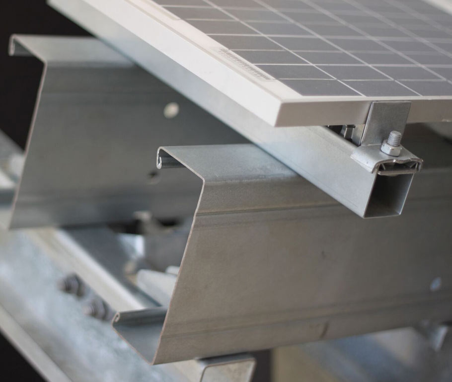
PV steel bracket Form: Hot-dip galvanized fixed steel bracket
2. Design Basis
a. Design according to current international and American Codes and Standards, there are:
ANSI/AISC 360-16 (Specification for Structural Steel Buildings)
ASCE/SEI 7-16 (Minimum Design Loads for Buildings and Other Structures)
AISI S100-16W/S1-18 (North American Specification for the Design of Cold-Formed Steel Structural Members)
ANSI/AISC 341-16 (Seismic Provision for Structural Steel Buildings)
ASTM A36/A36M-08 (Standard Specification for Carbon Structural Steel)
ASTM A572/A572M-15 (Standard Specification for High-Strength Low-Alloy Columbium-Vanadium Structural Steel)
ASTM A53/A53M-07 (Standard Specification for Pipe Steel Black and Hot dipped Zinc-coated, Welded and Seamless)
ASTM A568/A568M-15 (Standard Specification for Steel, Sheet, Carbon and High-strength, Low alloy, Hot-rolled and Cold-rolled, General requirements for)
ASME B18.2.6-05 (Fasteners for Use in Structural Applications)
AWS D1.1/D1.1M-2015 (Structural Welding Code-steel)
EN ISO 14713 (Zinc Coatings – Guidelines and Recommendations or the Protection Against Corrosion of Iron and Steel in Structures)
EN ISO 1461 (Hot Dip Galvanized Coatings on Fabricated Iron and Steel Articles – Specifications and Test Methods)
AISC 303-16 (Code of Standard Practice for Steel Buildings and Bridges)
ISO 9001 (Quality Management Systems – Requirements)
ISO 9224 (Corrosion of Metals and Alloys – Corrosivity of Atmospheres Guiding Values for the Corrosivity Categories)
b. Electrical and other professional information provided
c. Soil Investigation Report: xxxxxx.
PV Steel Structure, PV Steel Brackets
3. Basic Design Parameters
Design Year:
Risk Category:
Basic Wind Speed 3-second (MRI=? Years):
Design Wind Speed 3-second (MRI=? Years):
Soil Class:
4. Structural Materials Except Those Indicated in the Drawing
(1). Steel structure material:
- Grade 50 steel shall be used for columns, sloped beams and purlin. Their mechanical properties and chemical composition shall meet the requirements of ASTM A572/A572M-15 “Standard Specification for High-Strength Low-Alloy Columbium-Vanadium Structural Steel.”
- A36 steel shall be used for H-shaped steel piles, diagonal braces, purlin brackets and joint parts. Their mechanical properties and chemical composition shall meet the requirements of ASTM A36/A36M-08 “Standard Specification for Carbon Structural Steel.”
- Columns, sloped beams, and purlins shall be made of cold-formed steel. It shall meet the requirements of AISI S100-16W/S1-18 “North American Speciation for the Design of Cold-Formed Steel Structural Members.”
- 6063-T5 Aluminum ally shall be used for fixture and cushion, Anodic oxidation protection shall be used for anti-corrosion, and the minimum average thickness shall be 20um.
- Unspecified connected steel plates are A36.
(2). Welding material:
ANSI and AWS requirements shall apply to welded connections. Welded connections shall comply with the “Specified Specification for Shielded Metal Arc Welding Carbon Steel Electrodes” or AWS A5.5 / A5.5M “Specifications for Shielded Metal Low Alloy Steel Electrodes”
Welded connections will be designed as fillet welds or butt welds. Butt welds may be either complete-joint-penetration groove welds or partial-joint-penetration groove welds.
(3) Bolts
Bolts not specifically noted shall be common bolts and shall comply with ASTM A307 Gr A, Fu=410MPa
The bolts for the pressure blocks shall be 304 stainless steel (A2-70). The pressure blocks shall include plastic washers to prevent inter-galvanic corrosion.
5. Installation, Production, Acceptance
(1) Shop manufacture shall be in accordance with the provisions of the “Code of Standard Practice for Steel Buildings and Bridges” AISC 303-16.
(2) When cutting steel structures, the allowance material shall be reserved for welding. The cutting edge of all components shall be smooth and deburring, and the deformation caused during machining and welding shall be corrected under relevant requirements.
(3) The Fabricator shall prepare the necessary shop drawings, giving complete information on the fabrication of the structural components and joints, including the location, type, and size of all welds, bolts, and rivets. These drawings should clearly distinguish between welds and bolts at the factory or in the field. Shop drawings shall be made in conformity with good practice and with due regard to speed and economy in fabrication and erection.
(4) Cleaning and Coating:
A. All structural steel shall be protected in accordance with EN ISO 12044 and EN ISO 14713.
B. A corrosion-resistant coating shall be used Where corrosion may affect the structure. After fabrication, structural steel shall be adequately coated and protected by hot-dip galvanizing. The thickness of the hot-dip galvanizing shall comply with EN ISO 14713 and ISO 1461, but it shall have a minimum value of 80 microns unless otherwise specified.
C. All bolts (except stainless steel) shall be hot-dip galvanized. It’s recommended that galvanized anchor rods and nuts be purchased from the same supplier.
D. No cutting, drilling, bending, riveting, threading, or similar operation shall be permitted after galvanizing, and all hot dip galvanized components shall be protected carefully when transporting, handling, and fixing galvanized metalwork to prevent damage to the zinc coating.
(5). The Fabricator shall first produce a small quantity of steel components for pre-installation at the factory. Mass production shall be made only after successful installation. PV steel brackets shall meet the requirements of resisting strong wind, being anti-seismic, being anti-corrosion, and being quick to install.
(6). The manufacturer shall complete welding, rust removal, and galvanizing of all steel components in the workshop and transport them to the site after inspection.
(7). Steel members shall be carefully inspected before erection. Their number, length, verticality, and fatness must be checked to meet the design requirements and specifications.
(8). Before installing the steel structure, the locating axis, foundation axis, elevation, position of bolt at column foot, and material should be checked.
(9). All steel structures, including PV modules, shall be supported according to the actual situation, and their loads shall be carefully considered. In the erection process, stacking materials, steel brackets, or other loads shall be protected to prevent any deformation.
(10). Common bolts shall include elastic washers and flat washers to prevent loosening. After tightening, the exposed length of the bolt shall be 2-3 threads. After installation of the whale structure, the tightness of all bolts shall be inspected.
(11). Bolt holes shall be 1.5-2.0 mm larger than the bolts’ nominal diameter. Bolt installation shall be able to pass freely through the holes.
(12). The packaging of PV steel brackets shall comply with the corresponding standard requirements. The outer package shall be strong enough, and the internal products shall have strong protection measures and anti-collision measures. All packages shall be marked on the central position with the contents of loading and unloading methods, storage and transportation marks, and so on.
(13). All erection works shall be carried out in accordance with the requirements of the “Code of Standard Practice for Steel Buildings and Bridges” AISC 303-16. Reasonable construction measures should be taken to avoid excessive installation errors. The construction error limit of each component is as follows:
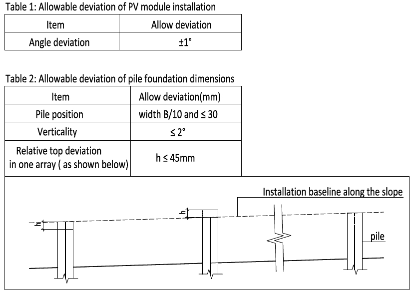
Example of PV Brackets Installation Limits
(14). Spare holes in the column can be used to adjust the column’s height to maintain the Angle Deviation. The dimensions marked in the drawing are for a typical manufacturing installation; they can be adjusted according to the site situation to ensure the robot’s operation.
6. Others:
- Except as indicated in the drawing, the dimension is in millimeters; the elevation is in meters.
- Without the designer’s consent, PV brackets cannot be added with extra loads.
- For lightning protection, see professional electrical drawings.
- The Construction unit shall be responsible for the safety of the bracket installation.
- PV modules should be able to withstand the maximum design wind loads.

