ZAM Coated Steel for Photovoltaic Brackets

Zink-aluminium-magnesium (ZAM) vs varmgalvanisering (HDG)

Definition

What is Zinc-Aluminum-Magnesium (ZAM)?

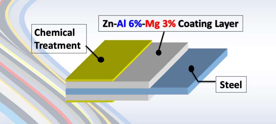
Zinc-aluminum-magnesium (ZAM) is a high-performance metallic coating applied to steel designed to offer superior corrosion resistance, durability, and heat resistance compared to traditional galvanizing (zinc-only coatings). The coating combines zinc (Zn), aluminum (Al), and magnesium (Mg), which provides unique advantages in various applications.
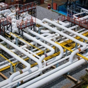
ZAM Coating

ZAM Coating

What is Hot-dip galvanizing? (HDG)?

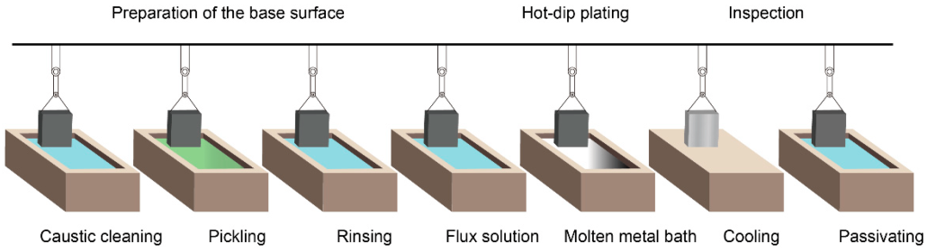
Hot-dip galvanization is a form of galvanization. It is the process of coating iron and steel with zinc, which alloys with the base metal surface when immersing the metal in a bath of molten zinc at a temperature of around 450 °C (842 °F). When exposed to the atmosphere, the pure zinc (Zn) reacts with oxygen (O2) to form zinc oxide (ZnO), which further reacts with carbon dioxide (CO2) to form zinc carbonate (ZnCO3), a usually dull grey, fairly strong material that protects the steel underneath from further corrosion in many circumstances.
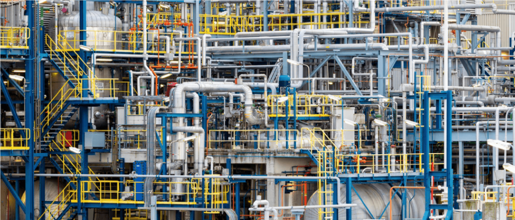
Hot-dip Galvanizing

Hot-dip Galvanizing

Main Differences: Zinc-Aluminum-Magnesium (ZAM) vs Hot-dip galvanizing (HDG)

The comparison between zinc-aluminum-magnesium (ZAM) og hot-dip galvanizing (HDG) revolves around their coating composition, corrosion resistance, applications, cost, og environmental impact. Below is a detailed comparison to help understand their differences:

1. Coating Composition

Zinc-Aluminum-Magnesium (ZAM):
ZAM coatings are made of a combination of zinc (Zn), aluminum (Al), og magnesium (Mg). Typically, the composition is about 80-90% Zinc, 5-11% Aluminum, og 1-3% Magnesium. Including aluminum and magnesium gives the coating superior properties compared to zinc alone.

Hot-Dip Galvanizing (HDG):
HDG involves immersing steel into a molten bath of zinc (Zn) to form a protective zinc coating. The coating consists almost entirely of zinc, with small amounts of iron from the substrate, forming a zinc-iron alloy layer.

2. Korrosionsbestandighed

Zinc-Aluminum-Magnesium (ZAM):
Superior corrosion resistance compared to hot-dip galvanized steel. Adding aluminum increases the coating’s resistance to high temperatures and oxidation, while magnesium improves its resistance to corrosion in harsh environments like coastal, industrial, and chemical settings. ZAM has self-healing properties—if the coating is damaged, the magnesium component reacts with moisture to help prevent further corrosion.

Hot-Dip Galvanizing (HDG):
It provides good corrosion resistance but not as high as ZAM, especially in aggressive environments. The zinc coating is sacrificial, meaning it corrodes first to protect the underlying steel, but its effectiveness can be limited in humid, salty, eller chemical environments. HDG does not have the advanced self-healing properties that ZAM offers.

3. Durability and Longevity

Zinc-Aluminum-Magnesium (ZAM):
ZAM-coated products can last 2 to 4 times longer than traditional galvanized steel in harsh environments (e.g., coastal areas, chemical plants, etc.). The coating’s enhanced resistance to environmental factors contributes to a longer service life.

Hot-Dip Galvanizing (HDG):
The lifespan of HDG products is good but generally shorter than ZAM, particularly in extreme conditions. HDG can last for many years in less corrosive environments (e.g., mild climates), but its protection may degrade faster in severe environments.

4. Applications

Zinc-Aluminum-Magnesium (ZAM):
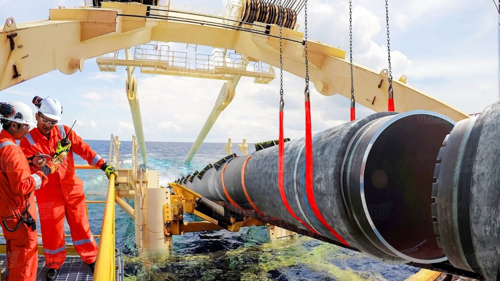
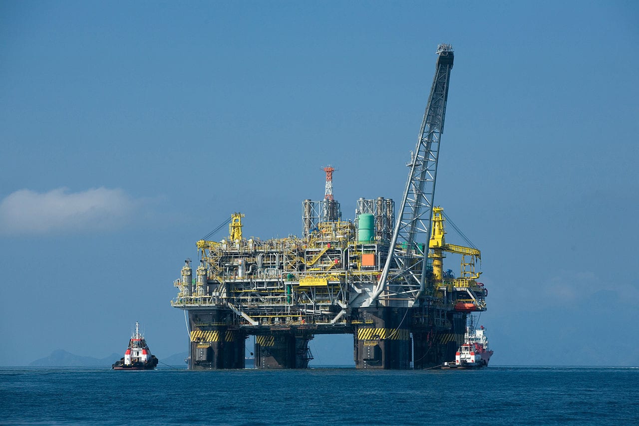
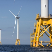
Ideal for barske miljøer such as Coastal areas (where saltwater exposure is high), Chemical and industrial environments (where exposure to aggressive substances is every day), Solar panel mounts (due to its superior durability), Heavy-duty industrial applications (e.g., agricultural and mining equipment, steel structures exposed to extreme weather conditions).

Hot-Dip Galvanizing (HDG):
It is commonly used in general construction, automotive industries, outdoor infrastructure, og agricultural applications. It is suitable for general-purpose corrosion protection in outdoor conditions but not recommended for extreme or coastal environments.

5. Cost

Zinc-Aluminum-Magnesium (ZAM):
It is more expensive than traditional hot-dip galvanizing due to the inclusion of aluminum and magnesium and the more advanced coating process. The longer lifespan and lower maintenance costs in harsh environments often justify the higher initial cost.

Hot-Dip Galvanizing (HDG):
It is cheaper than ZAM, making it more suitable for projects where cost-efficiency is a priority and the environment is less aggressive. The relatively lower cost makes it ideal for large-scale production.

6. Environmental Impact

Zinc-Aluminum-Magnesium (ZAM):
The production of ZAM coatings is more environmentally friendly than hot-dip galvanizing, as it involves lower emissions of harmful gases and waste materials. The production process for ZAM generally generates less waste og fewer harmful emissions compared to traditional galvanizing methods.

Hot-Dip Galvanizing (HDG):
It is more environmentally intensive than ZAM, producing more waste gases and wastewater. However, modern improvements in the HDG process have aimed to reduce the environmental footprint, though it remains higher than ZAM.

7. Aesthetic Appearance

Zinc-Aluminum-Magnesium (ZAM):
ZAM has a matte gray finish with a smoother, more uniform appearance. This appearance can be more desirable in specific applications like architectural structures or solar panel mounts.

Hot-Dip Galvanizing (HDG):
HDG often has a shiny or dull metallic finish, depending on the thickness of the coating. While durable, its aesthetic appearance may be less appealing than ZAM’s, especially if the finish is uneven.

8. Ease of Processing and Welding

Zinc-Aluminum-Magnesium (ZAM):
ZAM coatings can be more challenging to process, weld, og paint than traditional galvanized steel, creating issues in some applications.

Hot-Dip Galvanizing (HDG):
HDG products are easier to weld and process than ZAM. However, the zinc coating can make welding and cutting more difficult due to zinc fumes, and special precautions may be required.

Summary Comparison Table: Zinc-Aluminum-Magnesium (ZAM) vs Hot-dip Galvanizing (HDG)

Feature Zinc-Aluminum-Magnesium (ZAM) Hot-Dip Galvanizing (HDG)
Coating Composition Zinc, Aluminum, Magnesium Zinc (with some iron from the substrate)
Korrosionsbestandighed Superior, especially in harsh environments Good, but less effective in aggressive settings
Durability and Longevity 2-4 times longer than HDG in extreme environments Moderate lifespan, shorter in harsh conditions
Ansøgninger Coastal areas, chemical environments, heavy-duty General outdoor infrastructure, agriculture
Koste Higher initial cost Lower initial cost
Miljømæssig påvirkning Lower emissions and waste Higher emissions and waste
Aesthetic Appearance Matte gray, smoother finish Shiny or dull metallic finish
Ease of Processing It can be more challenging, especially with welding It is more straightforward to process and weld

Konklusion

ZAM is the best choice for extreme environments where superior corrosion resistance and durability are needed. Its long-term performance can justify the higher upfront cost.

HDG remains the go-to solution for general corrosion protection in less aggressive environments, providing a cost-effective and widely available option for most standard applications.

Pipeline vs Piping

Onshore vs Offshore Pipeline og Piping

Indledning

In the realm of energy transportation, the distinction between onshore and offshore pipelines and piping systems plays a crucial role in the efficiency, safety, and environmental impact of resource extraction and distribution. Onshore pipelines, typically situated on land, are designed to transport oil, gas, and other fluids over varying distances, benefiting from relatively more straightforward access for maintenance and monitoring. Conversely, offshore pipelines, laid on the seabed or suspended in water, present unique engineering challenges due to harsh marine conditions and logistical complexities. Understanding the Onshore vs Offshore Pipeline and Piping in design, construction, and operational considerations between these two types of pipelines is essential for optimizing infrastructure development and ensuring sustainable practices in the energy sector.

Definition: Onshore vs Offshore Pipeline and Piping

What is Pipeline?

Pipeline is a long series of pipes, usually of large diameter, running underground, aboveground and underwater, such as a submarine pipeline, and equipped with fittings, such as valves and pumps, to control the flow of large quantities of fluid over long distances. Pipelines have large diameters, making it easy to transport liquids or gases in bulk from one place to another, sometimes for thousands of miles.

Pipeline

Pipeline

What is Piping?

Rørføring is a system of pipes used to convey fluids (liquids and gases) from one location to another within the designated boundaries or spaces of petrochemical plants, power plants, refineries, etc. It is also equipped with valves and fittings to control the flow of fluids from one facility to another as needed, but only within the plant’s designated boundaries. Never skip these essential topics when taking an online course on piping engineering. Piping diameters range from 1/2 inch to 80 inches, depending on the facility’s design requirements for fluid transportation, usually from one facility to another within the facility’s boundaries.

Rørføring

Rørføring

What is Onshore Pipeline?

Onshore pipelines refer to networks of pipelines and related equipment used to transport fluids such as oil, natural gas, water, and chemicals in a land environment. These pipelines are integral to long-distance oil and gas transportation from oil fields to refineries, from natural gas wells to gas stations, and from crude oil and refined oil tank farms, chemical tank farms, LNG tank farms, and aircraft refueling pipeline operations.

Onshore Pipeline

Onshore Pipeline

What is Offshore Pipeline?

Offshore pipelines refer to the network of pipes and related equipment used to transport fluids such as oil, gas, water, and chemicals in an offshore environment. These pipelines are integral to operating offshore oil rigs, platforms and floating production storage and offloading units (FPSOs). The unique conditions of the offshore environment, such as high salinity, extreme temperatures, and strong currents, present significant challenges to the design and maintenance of these systems.

Offshore Pipeline

Offshore Pipeline

Main Differences: Onshore vs Offshore Pipeline and Piping

Comparison Table: Onshore vs Offshore Pipeline and Piping

Specifikation På land Offshore
Pipeline Rørføring Pipeline Rørføring
Design koder – ASME B31.4: Pipeline Transportation Systems for Liquids and Slurries
– ASME B31.8: Gas Transmission and Distribution Piping Systems
ASME B31.3: Process Piping – DNVGL-ST-F101: Submarine pipeline systems
– API RP 1111: Design, Construction, Operation, and Maintenance of Offshore Hydrocarbon Pipelines (Limit state design)
ASME B31.3: Process Piping
Omfang Outside plant boundary
(Villages, fields, rivers, canals, railways, highways, cities, deserts, forests, hills, etc.)
Within plant boundary Outside plant boundary Within plant boundary
Type of pipe API Spec 5L: Specification for Line pipes – ASTM
– BS
– API 5L
API Spec 5L: Specification for Line pipes
– DNVGL-ST-F101: Submarine Pipeline Systems
ASTM standarder
Ventiler – API 6D: Specification for Pipeline and Piping Valves
– Full Bore (FB) Ball Valves are used for pigs.
– BS
– API Standard
– Full bore (FB) and Reduced bore (RB)
– Full bore Valves: for smooth passage of intelligent pigs
– API 6D SS: Specification on Subsea Pipeline Valves
– RB valves
– BS/API standards
Svejsning – API Std. 1104: Welding of Pipelines and Related Facilities
– Type of welding: Automatic / Semi-Automatic/ Manual
– ASME Sec. IX: Standard for Welding and Brazing Procedures, Welders, Brazers and Welding and Brazing Operators
– Type of welding: Manual (mostly)
– API Std. 1104: Welding of Pipelines and Related Facilities
– Mostly automatic welding on pipelay barge.
– ASME Sec. IX: Standard for Welding and Brazing Procedures, Welders, Brazers and Welding and Brazing Operators
– Manual welding at the fabrication yard.
Weld joint inspection (NDT requirements) 100% by Automatic UT or RT (by using X-Ray) 5% to 100%
(mostly by using gamma rays)
100% by Automatic UT From 10% to 100% as required
Analyses – Wall Thickness Analysis
– Elastic Bend Radius Analysis
– Stability Analysis for Water Bodies/ Marshy Areas
– Horizontal directional drilling design analysis
– Railroad/ Highway Crossing Analysis
– Casing Pipe Analysis for Crossings
– Seismic Analysis
– Piping wall thickness calculation
– Piping Stress Analysis
Static Analysis
Dynamic Analysis
Wind Analysis
Flange Leakage Analysis
Seismic Analysis
– Wall thickness Analysis
– On-bottom Stability
– Span Analysis
– Global Buckling – Lateral and Upheaval
– Pipeline Expansion Analysis
– Riser Design (Span, Stress & Flexibility Analysis)
– Riser Clamp Design
– Pipeline Crossing Design and Analysis
– Deck piping stress analysis
Installation Buried (mostly) Above ground/On rack/slippers/T-postal etc. Subsea (in water on the seabed or buried in the seabed) Deck Platform Piping
(similar to plant)
Special Installations – Across rivers
– Horizontal Directional Drilling (HDD) method
– Micro-tunnelling method
– Across road/ rail/ highway
– Auger boring/ jacking boring method
– Shallow HDD
– Ghats/ Hills
– Modular installations
– Finning
– Studding
– Jacketing
– Spooling inside warehouse
– U/G piping for cooling water
– S-lay Method (for shallow water installation)
– J-Lay Method (for deep water installation)
– Shore pull/ barge pull near Land Fall Point (LFP)
Along with the deck structure
Special Equipment – Sectionalizing Valves (Remote operated)
– Insulating Joints
– Scraper Launcher/ Receiver
– Stem Extended Valves (for buried valves)
– Flow Tee
– Long Radius bends (R=6D)
– Cold field bends (R = 30D or 40D)
– Expansion Joints
– Motor Operator Valves (MOV)
– Cryogenic Valves
– Springs
– Subsea Isolation Valve (SSIV)
– LR Bends
– Flow tee
– Pipeline End Manifold (PLEM)
– Single Point Mooring (SPM) system
– Submarine hoses
– Floating hoses
– Cables and umbilical installation
– Piggy-back pipelines
Ikke relevant
Survey – Topographical Survey
(all along the pipeline route)
– Geotechnical investigation
(all along the pipeline route)
– Soil resistivity survey
(all along the pipeline route)
– Hydrological Survey for water bodies (for scour depth calculation)
– Cadastral Survey (for RoU acquisition)
– Wind profile from meteorology
– Seismic study of plot
– Geophysical survey/ Bathymetric Survey by using side scan sonar, sub-bottom profiler, and echo-sounder
– Met-Ocean data collection
– Geotechnical data of the pipeline route
Ikke relevant
Corrosion Protection Coating Three Layer Polyethylene (3LPE) coating
Three Layer Polypropylene (3LPP) coating
Fusion bonded epoxy (FBE) coating
– Coal tar enamel (CTE) Coating
Painting Coatings such as:
– Coal Tar Enamel Coating (CTE)
Three-layer polyethylene coating (3LPE)
Three-layer polypropylene coating (3LPP)
– Double-layer fusion bonded epoxy coating (2FBE)
Painting
Cathodic Protection System – Impressed Current Cathodic Protection (ICCP) system
– Sacrificial Anode (limited locations)
Not applicable Sacrificial Anodic Cathodic Protection (SACP) system Ikke relevant
Hydrostatic testing – Gauge Plate run of 95% of the ID of the highest pipe thickness
– Test Pressure
Minimum: 1.25 times of Design Pressure (for liquid pipelines)
1.25 to 1.5 times of Design Pressure (for gas pipelines)
Maximum: Pressure equivalent to Hoop stress of 95% of SMYS of pipe material
– Hold period: 24 hours
– No gauge plate run is done. Generally, cardboard blasting is done to clean the piping.
– Test Pressure
Minimum: 1.5 × Design Pressure × Temperature Factor
Maximum: Based on line schedule
– Hold period: 2 – 6 hours
– Gauge Plate run of 95% of the ID of the highest pipeline thickness.
– Test Pressure
Minimum: 1.25 times x Design Pressure
– Hold period: 24 hours
– No gauging is done.
– Test Pressure
Maximum: As per line schedule
– Hold period: 2 hours
Preservation – Preservation of pipeline with corrosion-inhibited water or by filling of inert gas (N2) Not applicable
Pigging Intelligent Pigging Not applicable Compliant Not applicable
Machines/Equipment required for installation – Trencher
– Backhoe/ Excavator
– Side Boom
– Cold field bending machine
– Holiday Detection Machines
– Pneumatic/ Hydraulic Internal Clamps
Crane/ Hydra – Pipelay Barge
– Derrick Barge
– Diving support vessel
– Dynamic Positioning (DP) barge (for deepwater)
Pre-fabricated deck piping

Conclusion: Onshore vs Offshore Pipeline and Piping

In summary, Onshore pipelines are usually buried or erected on land to transport oil, natural gas, drinking water, sewage, seawater, slurry, etc. Onshore piping is typically erected in petrochemical plants, power plants, refineries, fire protection systems, water treatment systems, etc., while Offshore pipelines are buried on the seabed. Offshore piping typically consists of transmission and structural support pipeline systems on offshore drilling platforms. Special offshore equipment includes underwater isolation valves, tees, and submarine hoses. Offshore surveys include geophysics, bathymetry, and ocean data collection, while onshore surveys focus on topographic and geotechnical engineering studies.

L80-9Cr vs L80-13Cr

L80-9Cr vs L80-13Cr: Noget du behøver at vide

Choosing the proper casing and tubing materials can ensure safety and efficiency in oil and gas drilling and exploration. L80-9Cr and L80-13Cr are two alloy steel grades commonly used in petroleum casing and tubing. Each grade has unique characteristics and applications. L80-9Cr vs L80-13Cr, this article will delve into the difference between these materials to help you make an informed decision.

1. Overview of L80 Grade

L80 is an alloy steel used in the oil and gas sector. It is known for its good strength and corrosion resistance. It is typically employed in high-temperature and high-pressure environments and is suitable for both oil and gas production.

1.1 L80-9Cr

Composition: Contains 9% chromium, enhancing the material’s oxidation resistance at high temperatures.
Egenskaber:
Corrosion Resistance: It performs well in CO2 environments, making it suitable for acidic gas pipelines.
Mechanical Strength: Provides good strength and is suitable for high-temperature operations.
Applications: Commonly used in high-temperature gas pipelines in oil fields.

1.2 L80-13Cr

Composition: Contains 13% chromium, offering higher corrosion resistance.
Egenskaber:
Corrosion Resistance: Exhibits superior performance in environments with H2S and CO2, suitable for extreme conditions.
Mechanical Strength: Offers higher strength and is ideal for complex operational environments.
Applications: Used in high-corrosion environments and deep well operations.

L80-9Cr vs L80-13Cr

L80-9Cr and L80-13Cr Casing and Tubing in Oil and Gas Drilling and Exploration

2. Comparison: L80-9Cr vs L80-13Cr

2.1 Chemical Composition

Standard karakter C Si Mn P S Cr Mo Ni Cu
API 5CT L80-9Cr ≤ 0,15 ≤ 1.00 0.30-0.60 ≤ 0,020 ≤ 0,010 8.00-10.00 0.90-1.10 ≤ 0.50 ≤ 0,25
L80-13Cr 0.15-0.22 ≤ 1.00 0.25-1.00 ≤ 0,020 ≤ 0,010 12.00-14.00 ≤ 0.50 ≤ 0,25

2.2 Mekaniske egenskaber

Standard karakter Yield Strength (Mpa) Trækstyrke (Mpa) Forlængelse (%) Hardness max
min. max. min. min. HRC HBW
API 5CT L80-9Cr 552 655 655 API 5CT
Table C.7
23 241
L80-13Cr 552 655 655 23 241

2.3 Impact Test

Standard karakter Sharpy Impact Energy (J)
Coupling Rørlegeme
API 5CT L80-9Cr L-10-40-0 T-10-20-0 L-10-27-0 T-10-14-0
L80-13Cr L-10-40-0 T-10-20-0 L-10-27-0 T-10-14-0

2.4 Corrosion Resistance

L80-9Cr: The 9% chromium content provides moderate corrosion resistance, suitable for environments with low to moderate concentrations of H₂S (hydrogen sulfide) or CO₂ (carbon dioxide), typically seen in less aggressive environments.

L80-13Cr: The 13% chromium content provides enhanced resistance to sour service (i.e., environments with high levels of H₂S) and high CO₂ environments. It’s better for harsher conditions like deep wells or offshore drilling.

2.5 Temperature and Sour Service

L80-9Cr: Generally suitable for moderate-temperature environments.

L80-13Cr: Can withstand higher temperatures and is better equipped for sour service conditions with high concentrations of H₂S or CO₂.

2.6 Cost

L80-9Cr: Due to its lower chromium content, L80-9Cr is less expensive than L80-13Cr. If the environment is not highly corrosive or sour, L80-9Cr could be a more cost-effective option.

L80-13Cr: More expensive but provides superior resistance in harsh conditions, potentially reducing maintenance costs or failures over time.

2.7 Applications

L80-9Cr: Suitable in wells with moderate temperature, pressure, and sour gas conditions. Often used in conventional oil and gas wells or less aggressive service environments.

L80-13Cr: Ideal for high-pressure wells with harsh environmental conditions, particularly in sour gas service, deep wells, or offshore oil & gas operations where high corrosion resistance is critical.

Offshore vindmøller

Strukturelle cirkulære hule sektioner til onshore og offshore vindmøller

I takt med at efterspørgslen efter vedvarende energi fortsætter med at stige globalt, er offshore vindkraft dukket op som en vital løsning. Denne artikel dykker ned i betydningen af strukturelle cirkulære hule sektioner (CHS), der anvendes i støttestrukturer af havvindmøller, og udforsker deres design, materialeegenskaber og anvendelser.

1. Forståelse af strukturelle cirkulære hule sektioner

Strukturelle cirkulære hulprofiler er cylindriske rør med et hult center. Disse sektioner spiller en afgørende rolle i understøtningskonstruktionerne af havvindmøller, som primært er designet til at bære møllens vægt og modstå ydre miljøbelastninger.

2. Materialeegenskaber af strukturelle cirkulære hule sektioner

Kulstofstål: S355MH, S355MLH, S420MH, S420MLH, S460MH, S460MLH, S460QH, S460QLH, S620QH, S620QLH, S690QH, S690QLH

3. Designovervejelser

Ved design af bærende konstruktioner til havvindmøller skal flere faktorer tages i betragtning:
Vindbelastning: Turbiner oplever dynamiske belastninger fra vind under drift, hvilket nødvendiggør et design, der sikrer strukturel stabilitet.
Bølgepåvirkning: Bølgerne i havmiljøer udøver yderligere pres på strukturer, hvilket kræver omhyggelige beregninger og designjusteringer.
Korrosionsbeskyttelse: På grund af havvandets korrosive karakter er det afgørende at bruge beskyttende belægninger eller korrosionsbestandige materialer for at forlænge strukturens levetid.

4. Fordele ved at bruge cirkulære hule sektioner

Anvendelse af cirkulære hule sektioner i støttekonstruktioner giver flere fordele:
Høj trykstyrke: Det cirkulære tværsnit giver mulighed for jævn trykfordeling, hvilket forbedrer den generelle stabilitet.
Letvægt: Sammenlignet med andre former giver cirkulære rør tilsvarende styrke med reduceret vægt, hvilket letter transport og installation.
Nem konstruktion: Enkelheden ved at forbinde og svejse cirkulære rør øger konstruktionens effektivitet.

5. Ofte stillede spørgsmål

Q: Hvilket materiale skal vælges til strukturelle cirkulære hule sektioner?
EN: Valget af materiale afhænger af specifikke miljøforhold, budget og designkrav. Kulstofstål er velegnet til de fleste anvendelser, men i stærkt korrosive miljøer kan rustfrit stål eller legeret stål være mere passende.

Q: Hvordan kan holdbarheden af strukturelle cirkulære hulsektioner sikres?
EN: Regelmæssige inspektioner og vedligeholdelse er afgørende for at sikre holdbarhed. Derudover kan valg af passende beskyttende belægninger og materialer forlænge strukturernes levetid betydeligt.

6. Konklusion

Strukturelle cirkulære hule sektioner er uundværlige i understøtningskonstruktioner af havvindmøller. Gennem omhyggeligt design og materialevalg kan vindmøller forbedres i stabilitet og holdbarhed og derved fremme udviklingen af vedvarende energi.

For yderligere forespørgsler eller assistance vedrørende strukturelle hulsektioner til onshore og offshore vindmøllekonstruktioner, er du velkommen til at kontakte på [email protected].

Råstålproduktion

Råstålproduktion i september 2024

I september 2024 var verdens råstålproduktion for de 71 lande, der rapporterede til World Steel Association (verdensstål), 143,6 millioner tons (Mt), et fald på 4,7% fra september 2023.

produktion af råstål

produktion af råstål

Råstålproduktion efter region

Afrika producerede 1,9 Mt i september 2024, en stigning på 2,61 TP3T i forhold til september 2023. Asien og Oceanien producerede 105,3 Mt, et fald på 5,01 TP3T. EU (27) producerede 10,5 Mt, en stigning på 0,3%. Europa, Andet produceret 3,6 Mt, op 4,1%. Mellemøsten producerede 3,5 Mt, et fald på 23,0%. Nordamerika producerede 8,6 Mt, et fald på 3,4%. Rusland og andre CIS + Ukraine producerede 6,8 Mt, et fald på 7,6%. Sydamerika producerede 3,5 Mt, en stigning på 3,3%.

Tabel 1. Råstålproduktion fordelt på region

Område september 2024 (Mt) % ændring 24/23 sep Jan-sep 2024 (Mt) % ændring jan-sep 24/23
Afrika 1.9 2.6 16.6 2.3
Asien og Oceanien 105.3 -5 1,032.00 -2.5
EU (27) 10.5 0.3 97.8 1.5
Europa, Andet 3.6 4.1 33.1 7.8
Mellemøsten 3.5 -23 38.4 -1.5
Nordamerika 8.6 -3.4 80 -3.9
Rusland og andre CIS + Ukraine 6.8 -7.6 64.9 -2.5
Sydamerika 3.5 3.3 31.4 0
I alt 71 lande 143.6 -4.7 1,394.10 -1.9

De 71 lande, der er inkluderet i denne tabel, tegnede sig for cirka 98% af verdens samlede råstålproduktion i 2023.

Regioner og lande omfattet af tabellen:

  • Afrika: Algeriet, Egypten, Libyen, Marokko, Sydafrika, Tunesien
  • Asien og Oceanien: Australien, Kina, Indien, Japan, Mongoliet, New Zealand, Pakistan, Sydkorea, Taiwan (Kina), Thailand, Vietnam
  • Den Europæiske Union (27): Østrig, Belgien, Bulgarien, Kroatien, Tjekkiet, Finland, Frankrig, Tyskland, Grækenland, Ungarn, Italien, Luxembourg, Nederlandene, Polen, Portugal, Rumænien, Slovakiet, Slovenien, Spanien, Sverige
  • Europa, andet: Makedonien, Norge, Serbien, Türkiye, Storbritannien
  • Mellemøsten: Bahrain, Iran, Irak, Jordan, Kuwait, Oman, Qatar, Saudi-Arabien, De Forenede Arabiske Emirater, Yemen
  • Nordamerika: Canada, Cuba, El Salvador, Guatemala, Mexico, USA
  • Rusland og andre CIS + Ukraine: Hviderusland, Kasakhstan, Rusland, Ukraine
  • Sydamerika: Argentina, Brasilien, Chile, Colombia, Ecuador, Paraguay, Peru, Uruguay, Venezuela

Top 10 stålproducerende lande

Kina producerede 77,1 Mt i september 2024, et fald på 6,1% i september 2023. Indien producerede 11,7 Mt, et fald på 0,2%. Japan producerede 6,6 Mt, et fald på 5,8%. USA producerede 6,7 Mt, en stigning på 1,2%. Rusland anslås at have produceret 5,6 Mt, et fald på 10,3%. Sydkorea producerede 5,5 Mt, en stigning på 1,3%. Tyskland producerede 3,0 Mt, en stigning på 4,3%. Türkiye producerede 3,1 Mt, op 6,5%. Brasilien producerede 2,8 Mt, en stigning på 9,9%. Iran anslås at have produceret 1,5 Mt, et fald på 41,2%.

Tabel 2. Top 10 stålproducerende lande

Område  september 2024 (Mt) % ændring 24/23 sep Jan-sep 2024 (Mt) % ændring jan-sep 24/23
Kina 77.1 -6.1 768.5 -3.6
Indien 11.7 -0.2 110.3 5.8
Japan 6.6 -5.8 63.3 -3.2
USA 6.7 1.2 60.3 -1.6
Rusland 5.6 e -10.3 54 -5.5
Sydkorea 5.5 1.3 48.1 -4.6
Tyskland 3 4.3 28.4 4
Türkiye 3.1 6.5 27.9 13.8
Brasilien 2.8 9.9 25.2 4.4
Iran 1,5 e -41.2 21.3 -3.1

e – anslået. Rangeringen af de 10 bedste producerende lande er baseret på år-til-dato aggregat

API 5L vs ISO 3183

Kend forskellene: API 5L vs ISO 3183

ISO 3183 og API 5L er standarder relateret til stålrør, primært til brug i olie-, gas- og andre væsketransportindustrier. Selvom der er betydelig overlapning mellem disse to standarder, API 5L vs ISO 3183, er der væsentlige forskelle i deres omfang, anvendelse og organisationerne bag dem.

1. Udstedende organisationer: API 5L vs. ISO 3183

API 5L: Udstedt af American Petroleum Institute (API), denne standard bruges primært i olie- og gasindustrien. Den beskriver de tekniske krav til stålrør, der transporterer olie, gas og vand.
ISO 3183: Udstedt af International Organization for Standardization (ISO), denne standard er internationalt anerkendt og bruges globalt til stålrør i olie- og gastransportsektoren.

2. Anvendelsesområde: API 5L vs. ISO 3183

API 5L: Dækker stålrør til transport af petroleum, naturgas og andre væsker under højt tryk. Det er meget udbredt i Nordamerika, især i USA.
ISO 3183: Denne standard fokuserer primært på design, fremstilling og kvalitetskontrol af stålrør, der anvendes i olie- og gasrørledninger, men dens anvendelse er mere international og anvendelig i forskellige lande verden over.

3. Nøgleforskelle: API 5L vs ISO 3183

Geografisk og markedsfokus:

API 5L er mere skræddersyet til det nordamerikanske marked (især USA), mens ISO 3183 er internationalt anvendelig og bruges i mange lande verden over.

Stålkvaliteter og krav:

API 5L definerer stålkvaliteter som L175, L210, L245 og så videre, hvor tallet repræsenterer minimum flydespænding i megapascal (MPa).
ISO 3183 definerer også lignende kvaliteter, men med mere detaljerede krav vedrørende materialeegenskaber, fremstillingsprocesser og inspektionsprotokoller, der er i overensstemmelse med international industripraksis.
Yderligere specifikationer:
API 5L lægger vægt på kvalitetskontrol, certificering og produktionskrav, hvorimod ISO 3183 dækker et bredere anvendelsesområde med international handel i tankerne og giver specifikationer for forskellige forhold, herunder temperatur, miljø og specifikke mekaniske krav.

4. Tekniske krav: API 5L vs ISO 3183

API 5L specificerer stålrørs materialeegenskaber, fremstillingsprocesser, dimensioner, testmetoder og kvalitetskontrol. Den definerer stålkvaliteter fra L (lav styrke) til X-kvaliteter (højere styrke), såsom X42, X60 og X70.
ISO 3183 dækker lignende aspekter af stålrørsfremstilling, herunder materialekvalitet, varmebehandling, overfladebehandling og rørender. Det giver også detaljerede specifikationer for rørledningsdesigntryk, miljøhensyn og forskelligt rørledningstilbehør.

5. Sammenligning af rørkvaliteter: API 5L vs. ISO 3183

API 5L: Kvaliteterne spænder fra L kvaliteter (lav flydespænding) til X kvaliteter (højere flydespænding). For eksempel refererer X60 til rør med en flydespænding på 60.000 psi (ca. 413 MPa).
ISO 3183: Den bruger et lignende karaktersystem, men kan indeholde mere detaljerede klassifikationer og betingelser. Det sikrer også overensstemmelse med global pipeline design og operationelle praksis.

6. Kompatibilitet mellem standarder:

I mange tilfælde er API 5L og ISO 3183 kompatible, hvilket betyder, at et stålrør, der opfylder kravene i API 5L, generelt også vil opfylde kravene i ISO 3183 og omvendt. Dog kan specifikke pipeline-projekter overholde den ene standard frem for den anden afhængigt af placering, klientpræferencer eller regulatoriske krav.

7. Konklusion:

API 5L er mere almindelig i USA og de omkringliggende regioner. Det fokuserer på olie- og gasrørledningsindustrien med stor vægt på produktion og kvalitetskontrol.
ISO 3183 er en international standard for globale olie- og gasrørledningsprojekter. Dens mere detaljerede, globalt tilpassede krav sikrer bredere accept på internationale markeder.

Begge standarder er meget ens med hensyn til materiale-, fremstillings- og testspecifikationer. Alligevel har ISO 3183 en tendens til at have et bredere, mere globalt anvendeligt anvendelsesområde, mens API 5L forbliver mere specifik for det nordamerikanske marked. Valget mellem disse standarder afhænger af rørledningsprojektets geografiske placering, specifikationer og regulatoriske behov.