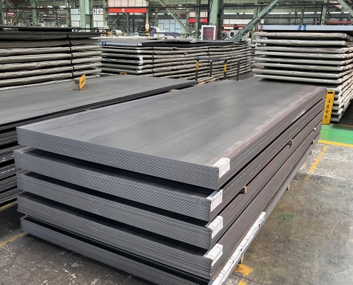
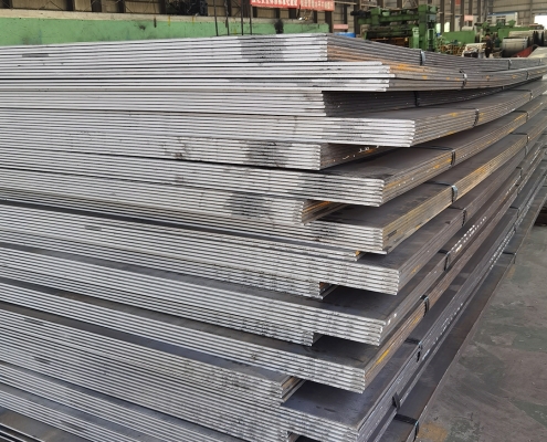
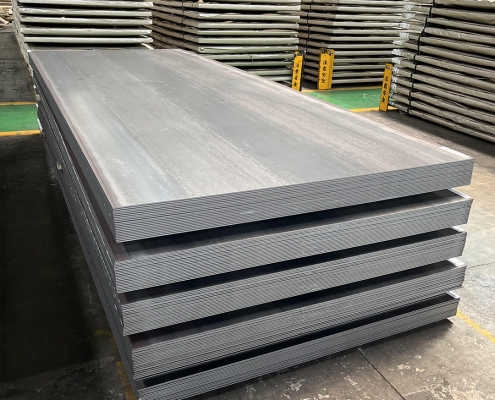
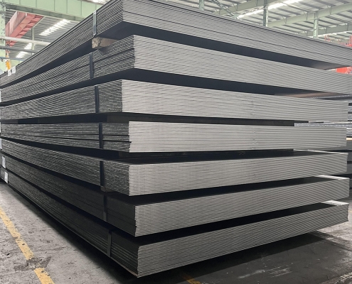
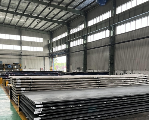
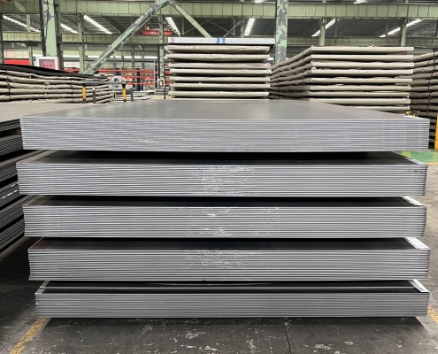
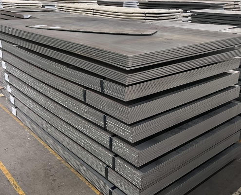
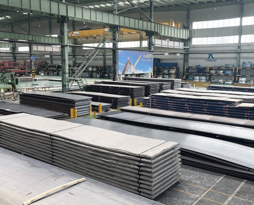
ZAM Coated Steel for Photovoltaic Brackets

Zink-Aluminium-Magnesium (ZAM) versus Thermisch verzinken (HDG)

Definitie

What is Zinc-Aluminum-Magnesium (ZAM)?

Zinc-aluminum-magnesium (ZAM) is a high-performance metallic coating applied to steel designed to offer superior corrosion resistance, durability, and heat resistance compared to traditional galvanizing (zinc-only coatings). The coating combines zinc (Zn), aluminum (Al), and magnesium (Mg), which provides unique advantages in various applications.

ZAM Coating

ZAM Coating

What is Hot-dip galvanizing? (HDG)?

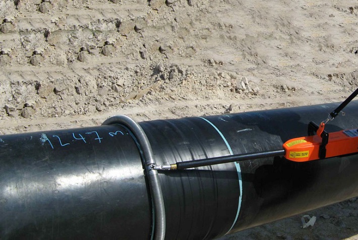
Hot-dip galvanization is a form of galvanization. It is the process of coating iron and steel with zinc, which alloys with the base metal surface when immersing the metal in a bath of molten zinc at a temperature of around 450 °C (842 °F). When exposed to the atmosphere, the pure zinc (Zn) reacts with oxygen (O2) to form zinc oxide (ZnO), which further reacts with carbon dioxide (CO2) to form zinc carbonate (ZnCO3), a usually dull grey, fairly strong material that protects the steel underneath from further corrosion in many circumstances.

Hot-dip Galvanizing

Hot-dip Galvanizing

Main Differences: Zinc-Aluminum-Magnesium (ZAM) vs Hot-dip galvanizing (HDG)

The comparison between zinc-aluminum-magnesium (ZAM) En hot-dip galvanizing (HDG) revolves around their coating composition, corrosion resistance, applications, cost, En environmental impact. Below is a detailed comparison to help understand their differences:

1. Coating Composition

Zinc-Aluminum-Magnesium (ZAM):
ZAM coatings are made of a combination of zinc (Zn), aluminum (Al), En magnesium (Mg). Typically, the composition is about 80-90% Zinc, 5-11% Aluminum, En 1-3% Magnesium. Including aluminum and magnesium gives the coating superior properties compared to zinc alone.

Hot-Dip Galvanizing (HDG):
HDG involves immersing steel into a molten bath of zinc (Zn) to form a protective zinc coating. The coating consists almost entirely of zinc, with small amounts of iron from the substrate, forming a zinc-iron alloy layer.

2. Corrosiebestendigheid

Zinc-Aluminum-Magnesium (ZAM):
Superior corrosion resistance compared to hot-dip galvanized steel. Adding aluminum increases the coating’s resistance to high temperatures and oxidation, while magnesium improves its resistance to corrosion in harsh environments like coastal, industrial, and chemical settings. ZAM has self-healing properties—if the coating is damaged, the magnesium component reacts with moisture to help prevent further corrosion.

Hot-Dip Galvanizing (HDG):
It provides good corrosion resistance but not as high as ZAM, especially in aggressive environments. The zinc coating is sacrificial, meaning it corrodes first to protect the underlying steel, but its effectiveness can be limited in humid, salty, of chemical environments. HDG does not have the advanced self-healing properties that ZAM offers.

3. Durability and Longevity

Zinc-Aluminum-Magnesium (ZAM):
ZAM-coated products can last 2 to 4 times longer than traditional galvanized steel in harsh environments (e.g., coastal areas, chemical plants, etc.). The coating’s enhanced resistance to environmental factors contributes to a longer service life.

Hot-Dip Galvanizing (HDG):
The lifespan of HDG products is good but generally shorter than ZAM, particularly in extreme conditions. HDG can last for many years in less corrosive environments (e.g., mild climates), but its protection may degrade faster in severe environments.

4. Applications

Zinc-Aluminum-Magnesium (ZAM):
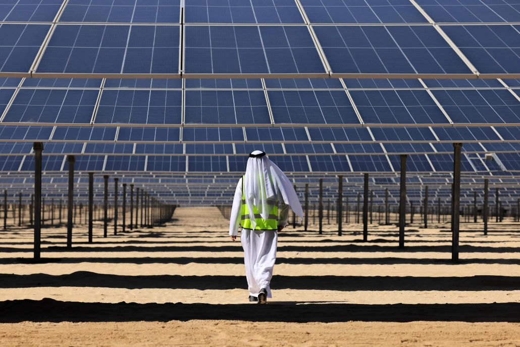
Ideal for zware omstandigheden such as Coastal areas (where saltwater exposure is high), Chemical and industrial environments (where exposure to aggressive substances is every day), Solar panel mounts (due to its superior durability), Heavy-duty industrial applications (e.g., agricultural and mining equipment, steel structures exposed to extreme weather conditions).

Hot-Dip Galvanizing (HDG):
It is commonly used in general construction, automotive industries, outdoor infrastructure, En agricultural applications. It is suitable for general-purpose corrosion protection in outdoor conditions but not recommended for extreme or coastal environments.

5. Cost

Zinc-Aluminum-Magnesium (ZAM):
It is more expensive than traditional hot-dip galvanizing due to the inclusion of aluminum and magnesium and the more advanced coating process. The longer lifespan and lower maintenance costs in harsh environments often justify the higher initial cost.

Hot-Dip Galvanizing (HDG):
It is cheaper than ZAM, making it more suitable for projects where cost-efficiency is a priority and the environment is less aggressive. The relatively lower cost makes it ideal for large-scale production.

6. Environmental Impact

Zinc-Aluminum-Magnesium (ZAM):
The production of ZAM coatings is more environmentally friendly than hot-dip galvanizing, as it involves lower emissions of harmful gases and waste materials. The production process for ZAM generally generates less waste En fewer harmful emissions compared to traditional galvanizing methods.

Hot-Dip Galvanizing (HDG):
It is more environmentally intensive than ZAM, producing more waste gases and wastewater. However, modern improvements in the HDG process have aimed to reduce the environmental footprint, though it remains higher than ZAM.

7. Aesthetic Appearance

Zinc-Aluminum-Magnesium (ZAM):
ZAM has a matte gray finish with a smoother, more uniform appearance. This appearance can be more desirable in specific applications like architectural structures or solar panel mounts.

Hot-Dip Galvanizing (HDG):
HDG often has a shiny or dull metallic finish, depending on the thickness of the coating. While durable, its aesthetic appearance may be less appealing than ZAM’s, especially if the finish is uneven.

8. Ease of Processing and Welding

Zinc-Aluminum-Magnesium (ZAM):
ZAM coatings can be more challenging to process, weld, En paint than traditional galvanized steel, creating issues in some applications.

Hot-Dip Galvanizing (HDG):
HDG products are easier to weld and process than ZAM. However, the zinc coating can make welding and cutting more difficult due to zinc fumes, and special precautions may be required.

Summary Comparison Table: Zinc-Aluminum-Magnesium (ZAM) vs Hot-dip Galvanizing (HDG)

Functie Zinc-Aluminum-Magnesium (ZAM) Hot-Dip Galvanizing (HDG)
Coating Composition Zinc, Aluminum, Magnesium Zinc (with some iron from the substrate)
Corrosieweerstand Superior, especially in harsh environments Good, but less effective in aggressive settings
Durability and Longevity 2-4 times longer than HDG in extreme environments Moderate lifespan, shorter in harsh conditions
Toepassingen Coastal areas, chemical environments, heavy-duty General outdoor infrastructure, agriculture
Kosten Higher initial cost Lower initial cost
Milieu-impact Lower emissions and waste Higher emissions and waste
Aesthetic Appearance Matte gray, smoother finish Shiny or dull metallic finish
Ease of Processing It can be more challenging, especially with welding It is more straightforward to process and weld

Conclusie

ZAM is the best choice for extreme environments where superior corrosion resistance and durability are needed. Its long-term performance can justify the higher upfront cost.

HDG remains the go-to solution for general corrosion protection in less aggressive environments, providing a cost-effective and widely available option for most standard applications.

Pipeline vs Piping

Onshore versus offshore pijpleidingen en leidingen

Invoering

In the realm of energy transportation, the distinction between onshore and offshore pipelines and piping systems plays a crucial role in the efficiency, safety, and environmental impact of resource extraction and distribution. Onshore pipelines, typically situated on land, are designed to transport oil, gas, and other fluids over varying distances, benefiting from relatively more straightforward access for maintenance and monitoring. Conversely, offshore pipelines, laid on the seabed or suspended in water, present unique engineering challenges due to harsh marine conditions and logistical complexities. Understanding the Onshore vs Offshore Pipeline and Piping in design, construction, and operational considerations between these two types of pipelines is essential for optimizing infrastructure development and ensuring sustainable practices in the energy sector.

Definition: Onshore vs Offshore Pipeline and Piping

What is Pipeline?

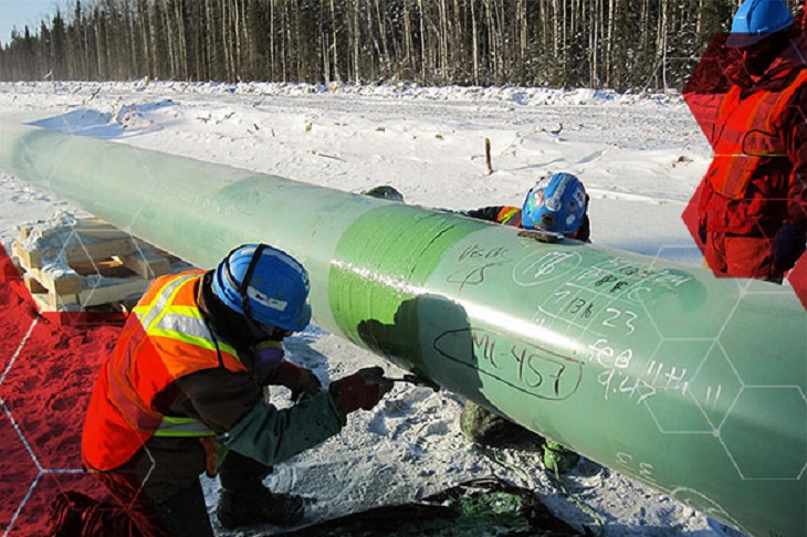
Pipeline is a long series of pipes, usually of large diameter, running underground, aboveground and underwater, such as a submarine pipeline, and equipped with fittings, such as valves and pumps, to control the flow of large quantities of fluid over long distances. Pipelines have large diameters, making it easy to transport liquids or gases in bulk from one place to another, sometimes for thousands of miles.

Pipeline

Pipeline

What is Piping?

Leidingen is a system of pipes used to convey fluids (liquids and gases) from one location to another within the designated boundaries or spaces of petrochemical plants, power plants, refineries, etc. It is also equipped with valves and fittings to control the flow of fluids from one facility to another as needed, but only within the plant’s designated boundaries. Never skip these essential topics when taking an online course on piping engineering. Piping diameters range from 1/2 inch to 80 inches, depending on the facility’s design requirements for fluid transportation, usually from one facility to another within the facility’s boundaries.

Leidingen

Leidingen

What is Onshore Pipeline?

Onshore pipelines refer to networks of pipelines and related equipment used to transport fluids such as oil, natural gas, water, and chemicals in a land environment. These pipelines are integral to long-distance oil and gas transportation from oil fields to refineries, from natural gas wells to gas stations, and from crude oil and refined oil tank farms, chemical tank farms, LNG tank farms, and aircraft refueling pipeline operations.

Onshore Pipeline

Onshore Pipeline

What is Offshore Pipeline?

Offshore pipelines refer to the network of pipes and related equipment used to transport fluids such as oil, gas, water, and chemicals in an offshore environment. These pipelines are integral to operating offshore oil rigs, platforms and floating production storage and offloading units (FPSOs). The unique conditions of the offshore environment, such as high salinity, extreme temperatures, and strong currents, present significant challenges to the design and maintenance of these systems.

Offshore Pipeline

Offshore Pipeline

Main Differences: Onshore vs Offshore Pipeline and Piping

Comparison Table: Onshore vs Offshore Pipeline and Piping

Specificatie Aan land Offshore
Pipeline Leidingen Pipeline Leidingen
Ontwerpcodes – ASME B31.4: Pipeline Transportation Systems for Liquids and Slurries
– ASME B31.8: Gas Transmission and Distribution Piping Systems
ASME B31.3: Process Piping – DNVGL-ST-F101: Submarine pipeline systems
– API RP 1111: Design, Construction, Operation, and Maintenance of Offshore Hydrocarbon Pipelines (Limit state design)
ASME B31.3: Process Piping
Domein Outside plant boundary
(Villages, fields, rivers, canals, railways, highways, cities, deserts, forests, hills, etc.)
Within plant boundary Outside plant boundary Within plant boundary
Type of pipe API Spec 5L: Specification for Line pipes – ASTM
– BS
– API 5L
API Spec 5L: Specification for Line pipes
– DNVGL-ST-F101: Submarine Pipeline Systems
ASTM-normen
Kleppen – API 6D: Specification for Pipeline and Piping Valves
– Full Bore (FB) Ball Valves are used for pigs.
– BS
– API Standard
– Full bore (FB) and Reduced bore (RB)
– Full bore Valves: for smooth passage of intelligent pigs
– API 6D SS: Specification on Subsea Pipeline Valves
– RB valves
– BS/API standards
Lassen – API Std. 1104: Welding of Pipelines and Related Facilities
– Type of welding: Automatic / Semi-Automatic/ Manual
– ASME Sec. IX: Standard for Welding and Brazing Procedures, Welders, Brazers and Welding and Brazing Operators
– Type of welding: Manual (mostly)
– API Std. 1104: Welding of Pipelines and Related Facilities
– Mostly automatic welding on pipelay barge.
– ASME Sec. IX: Standard for Welding and Brazing Procedures, Welders, Brazers and Welding and Brazing Operators
– Manual welding at the fabrication yard.
Weld joint inspection (NDT requirements) 100% by Automatic UT or RT (by using X-Ray) 5% to 100%
(mostly by using gamma rays)
100% by Automatic UT From 10% to 100% as required
Analyses – Wall Thickness Analysis
– Elastic Bend Radius Analysis
– Stability Analysis for Water Bodies/ Marshy Areas
– Horizontal directional drilling design analysis
– Railroad/ Highway Crossing Analysis
– Casing Pipe Analysis for Crossings
– Seismic Analysis
– Piping wall thickness calculation
– Piping Stress Analysis
Static Analysis
Dynamic Analysis
Wind Analysis
Flange Leakage Analysis
Seismic Analysis
– Wall thickness Analysis
– On-bottom Stability
– Span Analysis
– Global Buckling – Lateral and Upheaval
– Pipeline Expansion Analysis
– Riser Design (Span, Stress & Flexibility Analysis)
– Riser Clamp Design
– Pipeline Crossing Design and Analysis
– Deck piping stress analysis
Installatie Buried (mostly) Above ground/On rack/slippers/T-postal etc. Subsea (in water on the seabed or buried in the seabed) Deck Platform Piping
(similar to plant)
Special Installations – Across rivers
– Horizontal Directional Drilling (HDD) method
– Micro-tunnelling method
– Across road/ rail/ highway
– Auger boring/ jacking boring method
– Shallow HDD
– Ghats/ Hills
– Modular installations
– Finning
– Studding
– Jacketing
– Spooling inside warehouse
– U/G piping for cooling water
– S-lay Method (for shallow water installation)
– J-Lay Method (for deep water installation)
– Shore pull/ barge pull near Land Fall Point (LFP)
Along with the deck structure
Special Equipment – Sectionalizing Valves (Remote operated)
– Insulating Joints
– Scraper Launcher/ Receiver
– Stem Extended Valves (for buried valves)
– Flow Tee
– Long Radius bends (R=6D)
– Cold field bends (R = 30D or 40D)
– Expansion Joints
– Motor Operator Valves (MOV)
– Cryogenic Valves
– Springs
– Subsea Isolation Valve (SSIV)
– LR Bends
– Flow tee
– Pipeline End Manifold (PLEM)
– Single Point Mooring (SPM) system
– Submarine hoses
– Floating hoses
– Cables and umbilical installation
– Piggy-back pipelines
Niet van toepassing
Survey – Topographical Survey
(all along the pipeline route)
– Geotechnical investigation
(all along the pipeline route)
– Soil resistivity survey
(all along the pipeline route)
– Hydrological Survey for water bodies (for scour depth calculation)
– Cadastral Survey (for RoU acquisition)
– Wind profile from meteorology
– Seismic study of plot
– Geophysical survey/ Bathymetric Survey by using side scan sonar, sub-bottom profiler, and echo-sounder
– Met-Ocean data collection
– Geotechnical data of the pipeline route
Niet van toepassing
Corrosion Protection Coating Three Layer Polyethylene (3LPE) coating
Three Layer Polypropylene (3LPP) coating
Fusion bonded epoxy (FBE) coating
– Coal tar enamel (CTE) Coating
Painting Coatings such as:
– Coal Tar Enamel Coating (CTE)
Three-layer polyethylene coating (3LPE)
Three-layer polypropylene coating (3LPP)
– Double-layer fusion bonded epoxy coating (2FBE)
Painting
Cathodic Protection System – Impressed Current Cathodic Protection (ICCP) system
– Sacrificial Anode (limited locations)
Not applicable Sacrificial Anodic Cathodic Protection (SACP) system Niet van toepassing
Hydrostatic testing – Gauge Plate run of 95% of the ID of the highest pipe thickness
– Test Pressure
Minimum: 1.25 times of Design Pressure (for liquid pipelines)
1.25 to 1.5 times of Design Pressure (for gas pipelines)
Maximum: Pressure equivalent to Hoop stress of 95% of SMYS of pipe material
– Hold period: 24 hours
– No gauge plate run is done. Generally, cardboard blasting is done to clean the piping.
– Test Pressure
Minimum: 1.5 × Design Pressure × Temperature Factor
Maximum: Based on line schedule
– Hold period: 2 – 6 hours
– Gauge Plate run of 95% of the ID of the highest pipeline thickness.
– Test Pressure
Minimum: 1.25 times x Design Pressure
– Hold period: 24 hours
– No gauging is done.
– Test Pressure
Maximum: As per line schedule
– Hold period: 2 hours
Preservation – Preservation of pipeline with corrosion-inhibited water or by filling of inert gas (N2) Not applicable
Pigging Intelligent Pigging Not applicable Compliant Not applicable
Machines/Equipment required for installation – Trencher
– Backhoe/ Excavator
– Side Boom
– Cold field bending machine
– Holiday Detection Machines
– Pneumatic/ Hydraulic Internal Clamps
Crane/ Hydra – Pipelay Barge
– Derrick Barge
– Diving support vessel
– Dynamic Positioning (DP) barge (for deepwater)
Pre-fabricated deck piping

Conclusion: Onshore vs Offshore Pipeline and Piping

In summary, Onshore pipelines are usually buried or erected on land to transport oil, natural gas, drinking water, sewage, seawater, slurry, etc. Onshore piping is typically erected in petrochemical plants, power plants, refineries, fire protection systems, water treatment systems, etc., while Offshore pipelines are buried on the seabed. Offshore piping typically consists of transmission and structural support pipeline systems on offshore drilling platforms. Special offshore equipment includes underwater isolation valves, tees, and submarine hoses. Offshore surveys include geophysics, bathymetry, and ocean data collection, while onshore surveys focus on topographic and geotechnical engineering studies.

L80-9Cr vs L80-13Cr

L80-9Cr versus L80-13Cr: iets wat u moet weten

Choosing the proper casing and tubing materials can ensure safety and efficiency in oil and gas drilling and exploration. L80-9Cr and L80-13Cr are two alloy steel grades commonly used in petroleum casing and tubing. Each grade has unique characteristics and applications. L80-9Cr vs L80-13Cr, this article will delve into the difference between these materials to help you make an informed decision.

1. Overview of L80 Grade

L80 is an alloy steel used in the oil and gas sector. It is known for its good strength and corrosion resistance. It is typically employed in high-temperature and high-pressure environments and is suitable for both oil and gas production.

1.1 L80-9Cr

Composition: Contains 9% chromium, enhancing the material’s oxidation resistance at high temperatures.
Kenmerken:
Corrosion Resistance: It performs well in CO2 environments, making it suitable for acidic gas pipelines.
Mechanical Strength: Provides good strength and is suitable for high-temperature operations.
Applications: Commonly used in high-temperature gas pipelines in oil fields.

1.2 L80-13Cr

Composition: Contains 13% chromium, offering higher corrosion resistance.
Kenmerken:
Corrosion Resistance: Exhibits superior performance in environments with H2S and CO2, suitable for extreme conditions.
Mechanical Strength: Offers higher strength and is ideal for complex operational environments.
Applications: Used in high-corrosion environments and deep well operations.

L80-9Cr vs L80-13Cr

L80-9Cr and L80-13Cr Casing and Tubing in Oil and Gas Drilling and Exploration

2. Comparison: L80-9Cr vs L80-13Cr

2.1 Chemical Composition

Standaard Cijfer C Si Mn P S Cr ma Ni Cu
API5CT L80-9Cr ≤ 0,15 ≤ 1.00 0.30-0.60 ≤ 0,020 ≤ 0,010 8.00-10.00 0.90-1.10 ≤ 0.50 ≤ 0,25
L80-13Cr 0.15-0.22 ≤ 1.00 0.25-1.00 ≤ 0,020 ≤ 0,010 12.00-14.00 ≤ 0.50 ≤ 0,25

2.2 Mechanische eigenschappen

Standaard Cijfer Yield Strength (Mpa) Treksterkte (Mpa) Verlenging (%) Hardness max
min. max. min. min. HRC HBW
API5CT L80-9Cr 552 655 655 API5CT
Table C.7
23 241
L80-13Cr 552 655 655 23 241

2.3 Impact Test

Standaard Cijfer Sharpy Impact Energy (J)
Coupling Pijplichaam
API5CT L80-9Cr L-10-40-0 T-10-20-0 L-10-27-0 T-10-14-0
L80-13Cr L-10-40-0 T-10-20-0 L-10-27-0 T-10-14-0

2.4 Corrosion Resistance

L80-9Cr: The 9% chromium content provides moderate corrosion resistance, suitable for environments with low to moderate concentrations of H₂S (hydrogen sulfide) or CO₂ (carbon dioxide), typically seen in less aggressive environments.

L80-13Cr: The 13% chromium content provides enhanced resistance to sour service (i.e., environments with high levels of H₂S) and high CO₂ environments. It’s better for harsher conditions like deep wells or offshore drilling.

2.5 Temperature and Sour Service

L80-9Cr: Generally suitable for moderate-temperature environments.

L80-13Cr: Can withstand higher temperatures and is better equipped for sour service conditions with high concentrations of H₂S or CO₂.

2.6 Cost

L80-9Cr: Due to its lower chromium content, L80-9Cr is less expensive than L80-13Cr. If the environment is not highly corrosive or sour, L80-9Cr could be a more cost-effective option.

L80-13Cr: More expensive but provides superior resistance in harsh conditions, potentially reducing maintenance costs or failures over time.

2.7 Applications

L80-9Cr: Suitable in wells with moderate temperature, pressure, and sour gas conditions. Often used in conventional oil and gas wells or less aggressive service environments.

L80-13Cr: Ideal for high-pressure wells with harsh environmental conditions, particularly in sour gas service, deep wells, or offshore oil & gas operations where high corrosion resistance is critical.

Offshore windturbines

Structurele ronde holle secties voor onshore en offshore windturbines

Nu de vraag naar hernieuwbare energie wereldwijd blijft stijgen, is offshore windenergie een essentiële oplossing gebleken. Dit artikel duikt in de betekenis van structurele circulaire holle secties (CHS) die worden gebruikt in de ondersteunende structuren van offshore windturbines, waarbij het ontwerp, de materiaaleigenschappen en toepassingen ervan worden onderzocht.

1. Inzicht in structurele ronde holle secties

Structurele ronde holle profielen zijn cilindrische buizen met een hol midden. Deze secties spelen een cruciale rol in de ondersteunende structuren van offshore windturbines, die primair zijn ontworpen om het gewicht van de turbine te dragen en externe omgevingsdruk te weerstaan.

2. Materiaaleigenschappen van structurele ronde holle secties

Koolstofstaal: S355MH, S355MLH, S420MH, S420MLH, S460MH, S460MLH, S460QH, S460QLH, S620QH, S620QLH, S690QH, S690QLH

3. Ontwerpoverwegingen

Bij het ontwerpen van ondersteunende constructies voor offshore windturbines moeten verschillende factoren in overweging worden genomen:
Windbelasting: Turbines worden tijdens bedrijf blootgesteld aan dynamische windbelastingen. Daarom is een ontwerp nodig dat de stabiliteit van de constructie garandeert.
Golven: Golven in mariene omgevingen oefenen extra druk uit op constructies, waardoor zorgvuldige berekeningen en ontwerpaanpassingen nodig zijn.
Corrosiebescherming: Gezien de corrosieve aard van zeewater is het gebruik van beschermende coatings of corrosiebestendige materialen essentieel om de levensduur van de constructie te verlengen.

4. Voordelen van het gebruik van ronde holle secties

Het gebruik van ronde holle profielen in draagconstructies biedt verschillende voordelen:
Hoge druksterkte: de cirkelvormige doorsnede zorgt voor een gelijkmatige drukverdeling, wat de algehele stabiliteit verbetert.
Lichtgewicht: Vergeleken met andere vormen zijn ronde buizen even sterk, maar wegen ze minder. Hierdoor zijn ze gemakkelijker te transporteren en te installeren.
Eenvoudige constructie: het eenvoudig verbinden en lassen van ronde buizen verhoogt de efficiëntie van de constructie.

5. Veelgestelde vragen

Q: Welk materiaal moet worden gekozen voor ronde holle constructies?
A: De keuze van het materiaal hangt af van specifieke omgevingsomstandigheden, budget en ontwerpvereisten. Koolstofstaal is geschikt voor de meeste toepassingen, maar in zeer corrosieve omgevingen kan roestvrij staal of gelegeerd staal geschikter zijn.

Q: Hoe kan de duurzaamheid van ronde, holle constructies worden gewaarborgd?
A: Regelmatige inspecties en onderhoud zijn essentieel om duurzaamheid te garanderen. Bovendien kan het selecteren van geschikte beschermende coatings en materialen de levensduur van de structuren aanzienlijk verlengen.

6. Conclusie

Structurele ronde holle secties zijn onmisbaar in de ondersteunende structuren van offshore windturbines. Door zorgvuldig ontwerp en materiaalkeuze kunnen windturbines worden verbeterd in stabiliteit en duurzaamheid, waardoor de ontwikkeling van hernieuwbare energie wordt bevorderd.

Voor verdere vragen of hulp met betrekking tot structurele holle secties voor on- en offshore windturbinestructuren kunt u contact opnemen met [email protected].

Ruwe staalproductie

Ruwe staalproductie in september 2024

In september 2024 bedroeg de wereldwijde ruwstaalproductie voor de 71 landen die rapporteren aan de World Steel Association (wereldwijd staal) 143,6 miljoen ton (Mt), een daling van 4,71 TP3T ten opzichte van september 2023.

productie van ruw staal

productie van ruw staal

Ruwstaalproductie per regio

Afrika produceerde 1,9 Mt in september 2024, een stijging van 2,6% ten opzichte van september 2023. Azië en Oceanië produceerden 105,3 Mt, een daling van 5,0%. De EU (27) produceerde 10,5 Mt, een stijging van 0,3%. Europa, Overig produceerde 3,6 Mt, een stijging van 4,1%. Het Midden-Oosten produceerde 3,5 Mt, een daling van 23,0%. Noord-Amerika produceerde 8,6 Mt, een daling van 3,4%. Rusland en andere GOS + Oekraïne produceerden 6,8 Mt, een daling van 7,6%. Zuid-Amerika produceerde 3,5 Mt, een stijging van 3,3%.

Tabel 1. Ruwstaalproductie per regio

Regio Sep 2024 (maandag) % verandering 24/23 sept. Jan-Sep 2024 (Mt) % wijziging jan-sep 24/23
Afrika 1.9 2.6 16.6 2.3
Azië en Oceanië 105.3 -5 1,032.00 -2.5
EU (27) 10.5 0.3 97.8 1.5
Europa, Overig 3.6 4.1 33.1 7.8
Midden-Oosten 3.5 -23 38.4 -1.5
Noord-Amerika 8.6 -3.4 80 -3.9
Rusland en andere GOS-landen + Oekraïne 6.8 -7.6 64.9 -2.5
Zuid-Amerika 3.5 3.3 31.4 0
Totaal 71 landen 143.6 -4.7 1,394.10 -1.9

De 71 landen in deze tabel waren in 2023 goed voor ongeveer 98% van de totale wereldproductie van ruwstaal.

Regio's en landen die in de tabel worden behandeld:

  • Afrika: Algerije, Egypte, Libië, Marokko, Zuid-Afrika, Tunesië
  • Azië en Oceanië: Australië, China, India, Japan, Mongolië, Nieuw-Zeeland, Pakistan, Zuid-Korea, Taiwan (China), Thailand, Vietnam
  • Europese Unie (27): Oostenrijk, België, Bulgarije, Kroatië, Tsjechië, Finland, Frankrijk, Duitsland, Griekenland, Hongarije, Italië, Luxemburg, Nederland, Polen, Portugal, Roemenië, Slowakije, Slovenië, Spanje, Zweden
  • Europa, Overig: Macedonië, Noorwegen, Servië, Turkije, Verenigd Koninkrijk
  • Midden-Oosten: Bahrein, Iran, Irak, Jordanië, Koeweit, Oman, Qatar, Saoedi-Arabië, Verenigde Arabische Emiraten, Jemen
  • Noord-Amerika: Canada, Cuba, El Salvador, Guatemala, Mexico, Verenigde Staten
  • Rusland en andere GOS-landen + Oekraïne: Wit-Rusland, Kazachstan, Rusland, Oekraïne
  • Zuid-Amerika: Argentinië, Brazilië, Chili, Colombia, Ecuador, Paraguay, Peru, Uruguay, Venezuela

Top 10 staalproducerende landen

China produceerde 77,1 Mt in september 2024, een daling van 6,1% ten opzichte van september 2023. India produceerde 11,7 Mt, een daling van 0,2%. Japan produceerde 6,6 Mt, een daling van 5,8%. De Verenigde Staten produceerden 6,7 Mt, een stijging van 1,2%. Rusland heeft naar schatting 5,6 Mt geproduceerd, een daling van 10,3%. Zuid-Korea produceerde 5,5 Mt, een stijging van 1,3%. Duitsland produceerde 3,0 Mt, een stijging van 4,3%. Turkije produceerde 3,1 Mt, een stijging van 6,5%. Brazilië produceerde 2,8 Mt, een stijging van 9,9%. Iran heeft naar schatting 1,5 Mt geproduceerd, een daling van 41,2%.

Tabel 2. Top 10 staalproducerende landen

Regio  Sep 2024 (maandag) % verandering 24/23 sept. Jan-Sep 2024 (Mt) % wijziging jan-sep 24/23
China 77.1 -6.1 768.5 -3.6
Indië 11.7 -0.2 110.3 5.8
Japan 6.6 -5.8 63.3 -3.2
Verenigde Staten 6.7 1.2 60.3 -1.6
Rusland 5.6 en -10.3 54 -5.5
Zuid-Korea 5.5 1.3 48.1 -4.6
Duitsland 3 4.3 28.4 4
Turkije 3.1 6.5 27.9 13.8
Brazilië 2.8 9.9 25.2 4.4
Iran 1,5 e -41.2 21.3 -3.1

e – geschat. De rangschikking van de top 10 producerende landen is gebaseerd op het totaal van het jaar tot nu toe

API 5L versus ISO 3183

Ken de verschillen: API 5L versus ISO 3183

ISO 3183 en API 5L zijn normen gerelateerd aan stalen pijpen, voornamelijk voor gebruik in de olie-, gas- en andere vloeistoftransportindustrieën. Hoewel er een aanzienlijke overlap is tussen deze twee normen, API 5L vs ISO 3183, bestaan er belangrijke verschillen in hun scope, toepassing en de organisaties erachter.

1. Uitgevende organisaties: API 5L versus ISO 3183

API 5L: Uitgegeven door het American Petroleum Institute (API), deze standaard wordt voornamelijk gebruikt in de olie- en gasindustrie. Het beschrijft de technische vereisten voor stalen pijpen die olie, gas en water transporteren.
ISO 3183: Deze norm, uitgegeven door de International Organization for Standardization (ISO), wordt internationaal erkend en wereldwijd gebruikt voor stalen buizen in de olie- en gastransportsector.

2. Toepassingsgebied: API 5L versus ISO 3183

API 5L: Bestrijkt stalen buizen voor het transporteren van petroleum, aardgas en andere vloeistoffen onder hoge druk. Het wordt veel gebruikt in Noord-Amerika, met name in de Verenigde Staten.
ISO 3183: Deze norm richt zich primair op het ontwerp, de productie en de kwaliteitscontrole van stalen buizen die worden gebruikt in olie- en gasleidingen. De norm wordt echter ook internationaal toegepast en is in verschillende landen wereldwijd toepasbaar.

3. Belangrijkste verschillen: API 5L versus ISO 3183

Geografische en marktfocus:

API 5L is meer toegespitst op de Noord-Amerikaanse markt (met name de VS), terwijl ISO 3183 internationaal toepasbaar is en in veel landen over de hele wereld wordt gebruikt.

Staalsoorten en vereisten:

API 5L definieert staalsoorten zoals L175, L210, L245, enzovoort, waarbij het getal de minimale vloeigrens in megapascal (MPa) weergeeft.
ISO 3183 definieert ook soortgelijke klassen, maar met meer gedetailleerde eisen ten aanzien van materiaaleigenschappen, productieprocessen en inspectieprotocollen, in overeenstemming met de internationale praktijken in de sector.
Aanvullende specificaties:
API 5L legt de nadruk op kwaliteitscontrole, certificering en productievereisten, terwijl ISO 3183 een breder bereik bestrijkt, met name gericht op internationale handel, en specificaties biedt voor verschillende omstandigheden, waaronder temperatuur, omgeving en specifieke mechanische vereisten.

4. Technische vereisten: API 5L versus ISO 3183

API 5L specificeert de materiaaleigenschappen, productieprocessen, afmetingen, testmethoden en kwaliteitscontrole van stalen pijpen. Het definieert staalsoorten van L (lage sterkte) tot X-soorten (hogere sterkte), zoals X42, X60 en X70.
ISO 3183 behandelt vergelijkbare aspecten van de productie van stalen buizen, waaronder materiaalkwaliteit, warmtebehandeling, oppervlaktebehandeling en buisuiteinden. Het biedt ook gedetailleerde specificaties voor pijpleidingontwerpdruk, milieuoverwegingen en verschillende pijpleidingaccessoires.

5. Vergelijking van pijpkwaliteiten: API 5L versus ISO 3183

API 5L: De klassen variëren van L-klassen (lage vloeisterkte) tot X-klassen (hogere vloeisterkte). X60 verwijst bijvoorbeeld naar buizen met een vloeisterkte van 60.000 psi (ongeveer 413 MPa).
ISO 3183: Gebruikt een soortgelijk beoordelingssysteem, maar kan meer gedetailleerde classificaties en voorwaarden bevatten. Zorgt ook voor afstemming met wereldwijd pijpleidingontwerp en operationele praktijken.

6. Compatibiliteit tussen normen:

In veel gevallen zijn API 5L en ISO 3183 compatibel, wat betekent dat een stalen pijp die voldoet aan de vereisten van API 5L over het algemeen ook voldoet aan de vereisten van ISO 3183 en vice versa. Echter, specifieke pijpleidingprojecten kunnen zich houden aan de ene norm boven de andere, afhankelijk van de locatie, voorkeuren van de klant of wettelijke vereisten.

7. Conclusie:

API 5L komt vaker voor in de Verenigde Staten en omliggende regio's. Het richt zich op de olie- en gaspijpleidingindustrie, met een sterke nadruk op productie en kwaliteitscontrole.
ISO 3183 is een internationale standaard voor wereldwijde olie- en gaspijpleidingprojecten. De meer gedetailleerde, wereldwijd afgestemde vereisten zorgen voor een bredere acceptatie op internationale markten.

Beide normen lijken erg op elkaar wat betreft materiaal-, productie- en testspecificaties. Toch heeft ISO 3183 de neiging om een bredere, meer wereldwijd toepasbare scope te hebben, terwijl API 5L specifieker blijft voor de Noord-Amerikaanse markt. De keuze tussen deze normen hangt af van de geografische locatie, specificaties en wettelijke behoeften van het pijpleidingproject.