ZAM Coated Steel for Photovoltaic Brackets

Zinc-Aluminum-Magnesium (ZAM) vs Hot-dip galvanizing (HDG)

Definizione

What is Zinc-Aluminum-Magnesium (ZAM)?

Zinc-aluminum-magnesium (ZAM) is a high-performance metallic coating applied to steel designed to offer superior corrosion resistance, durability, and heat resistance compared to traditional galvanizing (zinc-only coatings). The coating combines zinc (Zn), aluminum (Al), and magnesium (Mg), which provides unique advantages in various applications.
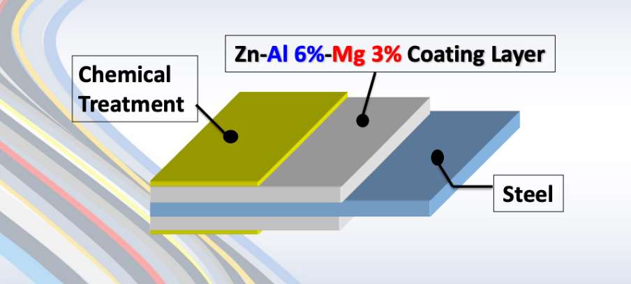
ZAM Coating

ZAM Coating

What is Hot-dip galvanizing? (HDG)?

Hot-dip galvanization is a form of galvanization. It is the process of coating iron and steel with zinc, which alloys with the base metal surface when immersing the metal in a bath of molten zinc at a temperature of around 450 °C (842 °F). When exposed to the atmosphere, the pure zinc (Zn) reacts with oxygen (O2) to form zinc oxide (ZnO), which further reacts with carbon dioxide (CO2) to form zinc carbonate (ZnCO3), a usually dull grey, fairly strong material that protects the steel underneath from further corrosion in many circumstances.

Hot-dip Galvanizing

Hot-dip Galvanizing

Main Differences: Zinc-Aluminum-Magnesium (ZAM) vs Hot-dip galvanizing (HDG)

The comparison between zinc-aluminum-magnesium (ZAM) E hot-dip galvanizing (HDG) revolves around their coating composition, corrosion resistance, applications, cost, E environmental impact. Below is a detailed comparison to help understand their differences:

1. Coating Composition

Zinc-Aluminum-Magnesium (ZAM):
ZAM coatings are made of a combination of zinc (Zn), aluminum (Al), E magnesium (Mg). Typically, the composition is about 80-90% Zinc, 5-11% Aluminum, E 1-3% Magnesium. Including aluminum and magnesium gives the coating superior properties compared to zinc alone.

Hot-Dip Galvanizing (HDG):
HDG involves immersing steel into a molten bath of zinc (Zn) to form a protective zinc coating. The coating consists almost entirely of zinc, with small amounts of iron from the substrate, forming a zinc-iron alloy layer.

2. Resistenza alla corrosione

Zinc-Aluminum-Magnesium (ZAM):
Superior corrosion resistance compared to hot-dip galvanized steel. Adding aluminum increases the coating’s resistance to high temperatures and oxidation, while magnesium improves its resistance to corrosion in harsh environments like coastal, industrial, and chemical settings. ZAM has self-healing properties—if the coating is damaged, the magnesium component reacts with moisture to help prevent further corrosion.

Hot-Dip Galvanizing (HDG):
It provides good corrosion resistance but not as high as ZAM, especially in aggressive environments. The zinc coating is sacrificial, meaning it corrodes first to protect the underlying steel, but its effectiveness can be limited in humid, salty, O chemical environments. HDG does not have the advanced self-healing properties that ZAM offers.

3. Durability and Longevity

Zinc-Aluminum-Magnesium (ZAM):
ZAM-coated products can last 2 to 4 times longer than traditional galvanized steel in harsh environments (e.g., coastal areas, chemical plants, etc.). The coating’s enhanced resistance to environmental factors contributes to a longer service life.

Hot-Dip Galvanizing (HDG):
The lifespan of HDG products is good but generally shorter than ZAM, particularly in extreme conditions. HDG can last for many years in less corrosive environments (e.g., mild climates), but its protection may degrade faster in severe environments.

4. Applications

Zinc-Aluminum-Magnesium (ZAM):
Ideal for ambienti difficili such as Coastal areas (where saltwater exposure is high), Chemical and industrial environments (where exposure to aggressive substances is every day), Solar panel mounts (due to its superior durability), Heavy-duty industrial applications (e.g., agricultural and mining equipment, steel structures exposed to extreme weather conditions).

Hot-Dip Galvanizing (HDG):
It is commonly used in general construction, automotive industries, outdoor infrastructure, E agricultural applications. It is suitable for general-purpose corrosion protection in outdoor conditions but not recommended for extreme or coastal environments.

5. Cost

Zinc-Aluminum-Magnesium (ZAM):
It is more expensive than traditional hot-dip galvanizing due to the inclusion of aluminum and magnesium and the more advanced coating process. The longer lifespan and lower maintenance costs in harsh environments often justify the higher initial cost.

Hot-Dip Galvanizing (HDG):
It is cheaper than ZAM, making it more suitable for projects where cost-efficiency is a priority and the environment is less aggressive. The relatively lower cost makes it ideal for large-scale production.

6. Environmental Impact

Zinc-Aluminum-Magnesium (ZAM):
The production of ZAM coatings is more environmentally friendly than hot-dip galvanizing, as it involves lower emissions of harmful gases and waste materials. The production process for ZAM generally generates less waste E fewer harmful emissions compared to traditional galvanizing methods.

Hot-Dip Galvanizing (HDG):
It is more environmentally intensive than ZAM, producing more waste gases and wastewater. However, modern improvements in the HDG process have aimed to reduce the environmental footprint, though it remains higher than ZAM.

7. Aesthetic Appearance

Zinc-Aluminum-Magnesium (ZAM):
ZAM has a matte gray finish with a smoother, more uniform appearance. This appearance can be more desirable in specific applications like architectural structures or solar panel mounts.

Hot-Dip Galvanizing (HDG):
HDG often has a shiny or dull metallic finish, depending on the thickness of the coating. While durable, its aesthetic appearance may be less appealing than ZAM’s, especially if the finish is uneven.

8. Ease of Processing and Welding

Zinc-Aluminum-Magnesium (ZAM):
ZAM coatings can be more challenging to process, weld, E paint than traditional galvanized steel, creating issues in some applications.

Hot-Dip Galvanizing (HDG):
HDG products are easier to weld and process than ZAM. However, the zinc coating can make welding and cutting more difficult due to zinc fumes, and special precautions may be required.

Summary Comparison Table: Zinc-Aluminum-Magnesium (ZAM) vs Hot-dip Galvanizing (HDG)

Caratteristica Zinc-Aluminum-Magnesium (ZAM) Hot-Dip Galvanizing (HDG)
Coating Composition Zinc, Aluminum, Magnesium Zinc (with some iron from the substrate)
Resistenza alla corrosione Superior, especially in harsh environments Good, but less effective in aggressive settings
Durability and Longevity 2-4 times longer than HDG in extreme environments Moderate lifespan, shorter in harsh conditions
Applicazioni Coastal areas, chemical environments, heavy-duty General outdoor infrastructure, agriculture
Costo Higher initial cost Lower initial cost
Impatto ambientale Lower emissions and waste Higher emissions and waste
Aesthetic Appearance Matte gray, smoother finish Shiny or dull metallic finish
Ease of Processing It can be more challenging, especially with welding It is more straightforward to process and weld

Conclusione

ZAM is the best choice for extreme environments where superior corrosion resistance and durability are needed. Its long-term performance can justify the higher upfront cost.

HDG remains the go-to solution for general corrosion protection in less aggressive environments, providing a cost-effective and widely available option for most standard applications.

Pipeline vs Piping

Onshore vs Offshore Pipeline and Piping

Introduzione

In the realm of energy transportation, the distinction between onshore and offshore pipelines and piping systems plays a crucial role in the efficiency, safety, and environmental impact of resource extraction and distribution. Onshore pipelines, typically situated on land, are designed to transport oil, gas, and other fluids over varying distances, benefiting from relatively more straightforward access for maintenance and monitoring. Conversely, offshore pipelines, laid on the seabed or suspended in water, present unique engineering challenges due to harsh marine conditions and logistical complexities. Understanding the Onshore vs Offshore Pipeline and Piping in design, construction, and operational considerations between these two types of pipelines is essential for optimizing infrastructure development and ensuring sustainable practices in the energy sector.

Definition: Onshore vs Offshore Pipeline and Piping

What is Pipeline?

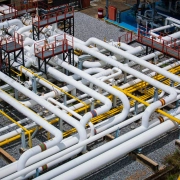
Pipeline is a long series of pipes, usually of large diameter, running underground, aboveground and underwater, such as a submarine pipeline, and equipped with fittings, such as valves and pumps, to control the flow of large quantities of fluid over long distances. Pipelines have large diameters, making it easy to transport liquids or gases in bulk from one place to another, sometimes for thousands of miles.

Pipeline

Pipeline

What is Piping?

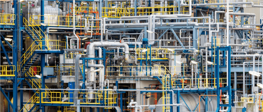
Tubazioni is a system of pipes used to convey fluids (liquids and gases) from one location to another within the designated boundaries or spaces of petrochemical plants, power plants, refineries, etc. It is also equipped with valves and fittings to control the flow of fluids from one facility to another as needed, but only within the plant’s designated boundaries. Never skip these essential topics when taking an online course on piping engineering. Piping diameters range from 1/2 inch to 80 inches, depending on the facility’s design requirements for fluid transportation, usually from one facility to another within the facility’s boundaries.

Tubazioni

Tubazioni

What is Onshore Pipeline?

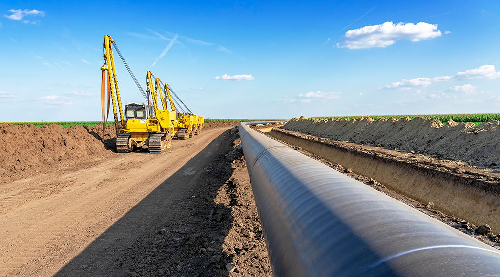
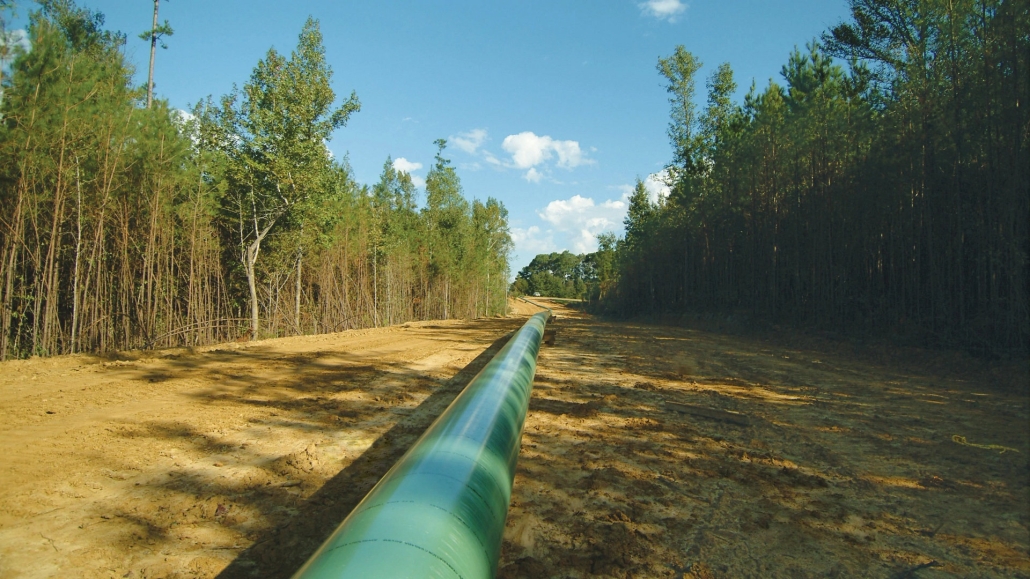
Onshore pipelines refer to networks of pipelines and related equipment used to transport fluids such as oil, natural gas, water, and chemicals in a land environment. These pipelines are integral to long-distance oil and gas transportation from oil fields to refineries, from natural gas wells to gas stations, and from crude oil and refined oil tank farms, chemical tank farms, LNG tank farms, and aircraft refueling pipeline operations.

Onshore Pipeline

Onshore Pipeline

What is Offshore Pipeline?

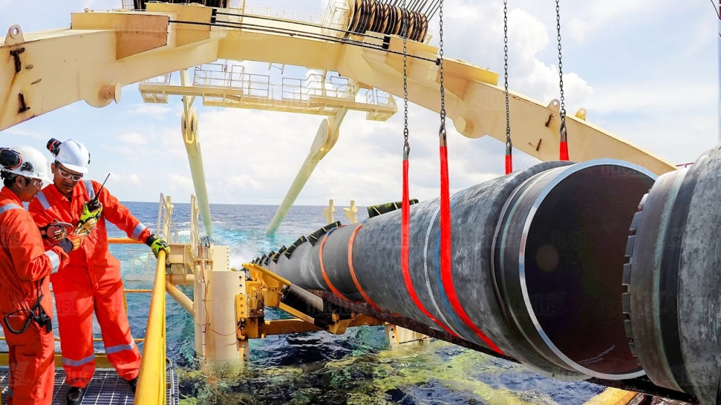
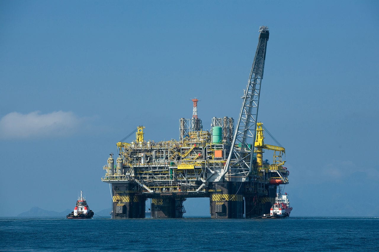
Offshore pipelines refer to the network of pipes and related equipment used to transport fluids such as oil, gas, water, and chemicals in an offshore environment. These pipelines are integral to operating offshore oil rigs, platforms and floating production storage and offloading units (FPSOs). The unique conditions of the offshore environment, such as high salinity, extreme temperatures, and strong currents, present significant challenges to the design and maintenance of these systems.

Offshore Pipeline

Offshore Pipeline

Main Differences: Onshore vs Offshore Pipeline and Piping

Comparison Table: Onshore vs Offshore Pipeline and Piping

Specifica A terra Al largo
Pipeline Tubazioni Pipeline Tubazioni
Codici di progettazione – ASME B31.4: Pipeline Transportation Systems for Liquids and Slurries
– ASME B31.8: Gas Transmission and Distribution Piping Systems
ASME B31.3: Process Piping – DNVGL-ST-F101: Submarine pipeline systems
– API RP 1111: Design, Construction, Operation, and Maintenance of Offshore Hydrocarbon Pipelines (Limit state design)
ASME B31.3: Process Piping
Scopo Outside plant boundary
(Villages, fields, rivers, canals, railways, highways, cities, deserts, forests, hills, etc.)
Within plant boundary Outside plant boundary Within plant boundary
Type of pipe API Spec 5L: Specification for Line pipes – ASTM
– BS
– API 5L
API Spec 5L: Specification for Line pipes
– DNVGl-ST-F101: Submarine Pipeline Systems
Norme ASTM
Valvole – API 6D: Specification for Pipeline and Piping Valves
– Full Bore (FB) Ball Valves are used for pigs.
– BS
– API Standard
– Full bore (FB) and Reduced bore (RB)
– Full bore Valves: for smooth passage of intelligent pigs
– API 6D SS: Specification on Subsea Pipeline Valves
– RB valves
– BS/API standards
Saldatura – API Std. 1104: Welding of Pipelines and Related Facilities
– Type of welding: Automatic / Semi-Automatic/ Manual
– ASME Sec. IX: Standard for Welding and Brazing Procedures, Welders, Brazers and Welding and Brazing Operators
– Type of welding: Manual (mostly)
– API Std. 1104: Welding of Pipelines and Related Facilities
– Mostly automatic welding on pipelay barge.
– ASME Sec. IX: Standard for Welding and Brazing Procedures, Welders, Brazers and Welding and Brazing Operators
– Manual welding at the fabrication yard.
Weld joint inspection (NDT requirements) 100% by Automatic UT or RT (by using X-Ray) 5% to 100%
(mostly by using gamma rays)
100% by Automatic UT From 10% to 100% as required
Analyses – Wall Thickness Analysis
– Elastic Bend Radius Analysis
– Stability Analysis for Water Bodies/ Marshy Areas
– Horizontal directional drilling design analysis
– Railroad/ Highway Crossing Analysis
– Casing Pipe Analysis for Crossings
– Seismic Analysis
– Piping wall thickness calculation
– Piping Stress Analysis
Static Analysis
Dynamic Analysis
Wind Analysis
Flange Leakage Analysis
Seismic Analysis
– Wall thickness Analysis
– On-bottom Stability
– Span Analysis
– Global Buckling – Lateral and Upheaval
– Pipeline Expansion Analysis
– Riser Design (Span, Stress & Flexibility Analysis)
– Riser Clamp Design
– Pipeline Crossing Design and Analysis
– Deck piping stress analysis
Installazione Buried (mostly) Above ground/On rack/slippers/T-postal etc. Subsea (in water on the seabed or buried in the seabed) Deck Platform Piping
(similar to plant)
Special Installations – Across rivers
– Horizontal Directional Drilling (HDD) method
– Micro-tunnelling method
– Across road/ rail/ highway
– Auger boring/ jacking boring method
– Shallow HDD
– Ghats/ Hills
– Modular installations
– Finning
– Studding
– Jacketing
– Spooling inside warehouse
– U/G piping for cooling water
– S-lay Method (for shallow water installation)
– J-Lay Method (for deep water installation)
– Shore pull/ barge pull near Land Fall Point (LFP)
Along with the deck structure
Special Equipment – Sectionalizing Valves (Remote operated)
– Insulating Joints
– Scraper Launcher/ Receiver
– Stem Extended Valves (for buried valves)
– Flow Tee
– Long Radius bends (R=6D)
– Cold field bends (R = 30D or 40D)
– Expansion Joints
– Motor Operator Valves (MOV)
– Cryogenic Valves
– Springs
– Subsea Isolation Valve (SSIV)
– LR Bends
– Flow tee
– Pipeline End Manifold (PLEM)
– Single Point Mooring (SPM) system
– Submarine hoses
– Floating hoses
– Cables and umbilical installation
– Piggy-back pipelines
Non applicabile
Survey – Topographical Survey
(all along the pipeline route)
– Geotechnical investigation
(all along the pipeline route)
– Soil resistivity survey
(all along the pipeline route)
– Hydrological Survey for water bodies (for scour depth calculation)
– Cadastral Survey (for RoU acquisition)
– Wind profile from meteorology
– Seismic study of plot
– Geophysical survey/ Bathymetric Survey by using side scan sonar, sub-bottom profiler, and echo-sounder
– Met-Ocean data collection
– Geotechnical data of the pipeline route
Non applicabile
Corrosion Protection Coating Three Layer Polyethylene (3LPE) coating
Three Layer Polypropylene (3LPP) coating
Fusion bonded epoxy (FBE) coating
– Coal tar enamel (CTE) Coating
Painting Coatings such as:
– Coal Tar Enamel Coating (CTE)
Three-layer polyethylene coating (3LPE)
Three-layer polypropylene coating (3LPP)
– Double-layer fusion bonded epoxy coating (2FBE)
Painting
Cathodic Protection System – Impressed Current Cathodic Protection (ICCP) system
– Sacrificial Anode (limited locations)
Not applicable Sacrificial Anodic Cathodic Protection (SACP) system Non applicabile
Hydrostatic testing – Gauge Plate run of 95% of the ID of the highest pipe thickness
– Test Pressure
Minimum: 1.25 times of Design Pressure (for liquid pipelines)
1.25 to 1.5 times of Design Pressure (for gas pipelines)
Maximum: Pressure equivalent to Hoop stress of 95% of SMYS of pipe material
– Hold period: 24 hours
– No gauge plate run is done. Generally, cardboard blasting is done to clean the piping.
– Test Pressure
Minimum: 1.5 × Design Pressure × Temperature Factor
Maximum: Based on line schedule
– Hold period: 2 – 6 hours
– Gauge Plate run of 95% of the ID of the highest pipeline thickness.
– Test Pressure
Minimum: 1.25 times x Design Pressure
– Hold period: 24 hours
– No gauging is done.
– Test Pressure
Maximum: As per line schedule
– Hold period: 2 hours
Preservation – Preservation of pipeline with corrosion-inhibited water or by filling of inert gas (N2) Not applicable
Pigging Intelligent Pigging Not applicable Compliant Not applicable
Machines/Equipment required for installation – Trencher
– Backhoe/ Excavator
– Side Boom
– Cold field bending machine
– Holiday Detection Machines
– Pneumatic/ Hydraulic Internal Clamps
Crane/ Hydra – Pipelay Barge
– Derrick Barge
– Diving support vessel
– Dynamic Positioning (DP) barge (for deepwater)
Pre-fabricated deck piping

Conclusion: Onshore vs Offshore Pipeline and Piping

In summary, Onshore pipelines are usually buried or erected on land to transport oil, natural gas, drinking water, sewage, seawater, slurry, etc. Onshore piping is typically erected in petrochemical plants, power plants, refineries, fire protection systems, water treatment systems, etc., while Offshore pipelines are buried on the seabed. Offshore piping typically consists of transmission and structural support pipeline systems on offshore drilling platforms. Special offshore equipment includes underwater isolation valves, tees, and submarine hoses. Offshore surveys include geophysics, bathymetry, and ocean data collection, while onshore surveys focus on topographic and geotechnical engineering studies.

L80-9Cr vs L80-13Cr

L80-9Cr vs L80-13Cr: Something You Need to Know

Choosing the proper casing and tubing materials can ensure safety and efficiency in oil and gas drilling and exploration. L80-9Cr and L80-13Cr are two alloy steel grades commonly used in petroleum casing and tubing. Each grade has unique characteristics and applications. L80-9Cr vs L80-13Cr, this article will delve into the difference between these materials to help you make an informed decision.

1. Overview of L80 Grade

L80 is an alloy steel used in the oil and gas sector. It is known for its good strength and corrosion resistance. It is typically employed in high-temperature and high-pressure environments and is suitable for both oil and gas production.

1.1 L80-9Cr

Composition: Contains 9% chromium, enhancing the material’s oxidation resistance at high temperatures.
Caratteristiche:
Corrosion Resistance: It performs well in CO2 environments, making it suitable for acidic gas pipelines.
Mechanical Strength: Provides good strength and is suitable for high-temperature operations.
Applications: Commonly used in high-temperature gas pipelines in oil fields.

1.2 L80-13Cr

Composition: Contains 13% chromium, offering higher corrosion resistance.
Caratteristiche:
Corrosion Resistance: Exhibits superior performance in environments with H2S and CO2, suitable for extreme conditions.
Mechanical Strength: Offers higher strength and is ideal for complex operational environments.
Applications: Used in high-corrosion environments and deep well operations.

L80-9Cr vs L80-13Cr

L80-9Cr and L80-13Cr Casing and Tubing in Oil and Gas Drilling and Exploration

2. Comparison: L80-9Cr vs L80-13Cr

2.1 Chemical Composition

Standard Grado C Mn P S Cr Mo Ni Cu
API5CT L80-9Cr ≤ 0,15 ≤ 1.00 0.30-0.60 ≤ 0,020 ≤ 0,010 8.00-10.00 0.90-1.10 ≤ 0.50 ≤ 0,25
L80-13Cr 0.15-0.22 ≤ 1.00 0.25-1.00 ≤ 0,020 ≤ 0,010 12.00-14.00 ≤ 0.50 ≤ 0,25

2.2 Proprietà meccaniche

Standard Grado Yield Strength (Mpa) Resistenza alla trazione (Mpa) Allungamento (%) Hardness max
min. max. min. min. HRC HBW
API5CT L80-9Cr 552 655 655 API5CT
Table C.7
23 241
L80-13Cr 552 655 655 23 241

2.3 Impact Test

Standard Grado Sharpy Impact Energy (J)
Coupling Corpo del tubo
API5CT L80-9Cr L-10-40-0 T-10-20-0 L-10-27-0 T-10-14-0
L80-13Cr L-10-40-0 T-10-20-0 L-10-27-0 T-10-14-0

2.4 Corrosion Resistance

L80-9Cr: The 9% chromium content provides moderate corrosion resistance, suitable for environments with low to moderate concentrations of H₂S (hydrogen sulfide) or CO₂ (carbon dioxide), typically seen in less aggressive environments.

L80-13Cr: The 13% chromium content provides enhanced resistance to sour service (i.e., environments with high levels of H₂S) and high CO₂ environments. It’s better for harsher conditions like deep wells or offshore drilling.

2.5 Temperature and Sour Service

L80-9Cr: Generally suitable for moderate-temperature environments.

L80-13Cr: Can withstand higher temperatures and is better equipped for sour service conditions with high concentrations of H₂S or CO₂.

2.6 Cost

L80-9Cr: Due to its lower chromium content, L80-9Cr is less expensive than L80-13Cr. If the environment is not highly corrosive or sour, L80-9Cr could be a more cost-effective option.

L80-13Cr: More expensive but provides superior resistance in harsh conditions, potentially reducing maintenance costs or failures over time.

2.7 Applications

L80-9Cr: Suitable in wells with moderate temperature, pressure, and sour gas conditions. Often used in conventional oil and gas wells or less aggressive service environments.

L80-13Cr: Ideal for high-pressure wells with harsh environmental conditions, particularly in sour gas service, deep wells, or offshore oil & gas operations where high corrosion resistance is critical.

Turbine eoliche offshore

Sezioni cave circolari strutturali per turbine eoliche onshore e offshore

Poiché la domanda di energia rinnovabile continua ad aumentare a livello globale, l'energia eolica offshore è emersa come una soluzione vitale. Questo articolo approfondisce il significato delle sezioni cave circolari strutturali (CHS) utilizzate nelle strutture di supporto delle turbine eoliche offshore, esplorandone la progettazione, le proprietà dei materiali e le applicazioni.

1. Comprensione delle sezioni cave circolari strutturali

Sezioni cave circolari strutturali sono tubi cilindrici con un centro cavo. Queste sezioni svolgono un ruolo cruciale nelle strutture di supporto delle turbine eoliche offshore, che sono progettate principalmente per sostenere il peso della turbina e resistere alle pressioni ambientali esterne.

2. Proprietà dei materiali delle sezioni cave circolari strutturali

Acciaio al carbonio: S355MH, S355MLH, S420MH, S420MLH, S460MH, S460MLH, S460QH, S460QLH, S620QH, S620QLH, S690QH, S690QLH

3. Considerazioni sulla progettazione

Quando si progettano strutture di supporto per turbine eoliche offshore, è necessario considerare diversi fattori:
Carico del vento: durante il funzionamento, le turbine sono sottoposte a carichi dinamici dovuti al vento, rendendo necessaria una progettazione che ne garantisca la stabilità strutturale.
Impatto delle onde: le onde negli ambienti marini esercitano una pressione aggiuntiva sulle strutture, che richiede calcoli accurati e adeguamenti progettuali.
Protezione dalla corrosione: data la natura corrosiva dell'acqua di mare, l'utilizzo di rivestimenti protettivi o materiali resistenti alla corrosione è essenziale per prolungare la durata della struttura.

4. Vantaggi dell'utilizzo di sezioni cave circolari

L'impiego di sezioni cave circolari nelle strutture di supporto offre diversi vantaggi:
Elevata resistenza alla compressione: la sezione circolare consente una distribuzione uniforme della pressione, migliorando la stabilità complessiva.
Leggero: rispetto ad altre forme, i tubi circolari offrono una resistenza simile con un peso ridotto, facilitando il trasporto e l'installazione.
Facilità di costruzione: la semplicità di collegamento e saldatura dei tubi circolari aumenta l'efficienza della costruzione.

5. Domande frequenti

Q: Quale materiale si dovrebbe scegliere per i profilati cavi circolari strutturali?
UN: La scelta del materiale dipende dalle condizioni ambientali specifiche, dal budget e dai requisiti di progettazione. L'acciaio al carbonio è adatto per la maggior parte delle applicazioni, ma in ambienti altamente corrosivi, l'acciaio inossidabile o l'acciaio legato potrebbero essere più appropriati.

Q: Come si può garantire la durabilità dei profilati cavi circolari strutturali?
UN: Ispezioni e manutenzioni regolari sono essenziali per garantire la durevolezza. Inoltre, la selezione di rivestimenti e materiali protettivi appropriati può estendere significativamente la durata delle strutture.

6. Conclusion

Le sezioni cave circolari strutturali sono indispensabili nelle strutture di supporto delle turbine eoliche offshore. Attraverso un'attenta progettazione e selezione dei materiali, le turbine eoliche possono essere migliorate in termini di stabilità e durata, favorendo così lo sviluppo delle energie rinnovabili.

Per ulteriori informazioni o assistenza in merito alle sezioni cave strutturali per strutture di turbine eoliche onshore e offshore, non esitate a contattarci a [email protected].

Produzione di acciaio grezzo

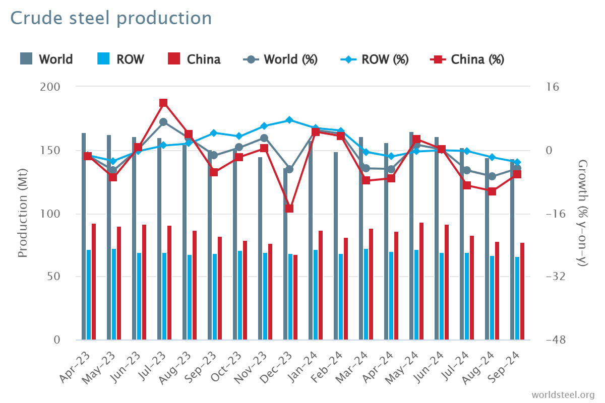
Produzione di acciaio grezzo a settembre 2024

Nel settembre 2024, la produzione mondiale di acciaio grezzo per i 71 paesi che fanno capo alla World Steel Association (acciaio mondiale) è stata di 143,6 milioni di tonnellate (Mt), con un calo di 4,7% rispetto a settembre 2023.

produzione di acciaio grezzo

produzione di acciaio grezzo

Produzione di acciaio grezzo per regione

L'Africa ha prodotto 1,9 Mt a settembre 2024, in aumento di 2,6% rispetto a settembre 2023. L'Asia e l'Oceania hanno prodotto 105,3 Mt, in calo di 5,0%. L'UE (27) ha prodotto 10,5 Mt, in aumento di 0,3%. L'Europa, altro ha prodotto 3,6 Mt, in aumento di 4,1%. Il Medio Oriente ha prodotto 3,5 Mt, in calo di 23,0%. Il Nord America ha prodotto 8,6 Mt, in calo di 3,4%. La Russia e altri paesi della CSI + Ucraina hanno prodotto 6,8 Mt, in calo di 7,6%. Il Sud America ha prodotto 3,5 Mt, in aumento di 3,3%.

Tabella 1. Produzione di acciaio grezzo per regione

Regione Settembre 2024 (Mt) % modifica 24/23 settembre Gen-Set 2024 (Mt) % cambia gen-set 24/23
Africa 1.9 2.6 16.6 2.3
Asia e Oceania 105.3 -5 1,032.00 -2.5
UE (27) 10.5 0.3 97.8 1.5
Europa, Altro 3.6 4.1 33.1 7.8
Medio Oriente 3.5 -23 38.4 -1.5
America del Nord 8.6 -3.4 80 -3.9
Russia e altri paesi della CSI + Ucraina 6.8 -7.6 64.9 -2.5
Sud America 3.5 3.3 31.4 0
Totale 71 paesi 143.6 -4.7 1,394.10 -1.9

I 71 paesi inclusi in questa tabella rappresentavano circa 98% della produzione mondiale totale di acciaio grezzo nel 2023.

Regioni e paesi coperti dalla tabella:

  • Africa: Algeria, Egitto, Libia, Marocco, Sudafrica, Tunisia
  • Asia e Oceania: Australia, Cina, India, Giappone, Mongolia, Nuova Zelanda, Pakistan, Corea del Sud, Taiwan (Cina), Thailandia, Vietnam
  • Unione Europea (27): Austria, Belgio, Bulgaria, Croazia, Repubblica Ceca, Finlandia, Francia, Germania, Grecia, Ungheria, Italia, Lussemburgo, Paesi Bassi, Polonia, Portogallo, Romania, Slovacchia, Slovenia, Spagna, Svezia
  • Europa, Altro: Macedonia, Norvegia, Serbia, Turchia, Regno Unito
  • Medio Oriente: Bahrein, Iran, Iraq, Giordania, Kuwait, Oman, Qatar, Arabia Saudita, Emirati Arabi Uniti, Yemen
  • America del Nord: Canada, Cuba, El Salvador, Guatemala, Messico, Stati Uniti
  • Russia e altri paesi della CSI + Ucraina: Bielorussia, Kazakistan, Russia, Ucraina
  • Sud America: Argentina, Brasile, Cile, Colombia, Ecuador, Paraguay, Perù, Uruguay, Venezuela

I 10 principali paesi produttori di acciaio

La Cina ha prodotto 77,1 Mt a settembre 2024, in calo di 6,1% rispetto a settembre 2023. L'India ha prodotto 11,7 Mt, in calo di 0,2%. Il Giappone ha prodotto 6,6 Mt, in calo di 5,8%. Gli Stati Uniti hanno prodotto 6,7 Mt, in aumento di 1,2%. Si stima che la Russia abbia prodotto 5,6 Mt, in calo di 10,3%. La Corea del Sud ha prodotto 5,5 Mt, in aumento di 1,3%. La Germania ha prodotto 3,0 Mt, in aumento di 4,3%. La Turchia ha prodotto 3,1 Mt, in aumento di 6,5%. Il Brasile ha prodotto 2,8 Mt, in aumento di 9,9%. Si stima che l'Iran abbia prodotto 1,5 Mt, in calo di 41,2%.

Tabella 2. I 10 principali paesi produttori di acciaio

Regione  Settembre 2024 (Mt) % modifica 24/23 settembre Gen-Set 2024 (Mt) % cambia gen-set 24/23
Cina 77.1 -6.1 768.5 -3.6
India 11.7 -0.2 110.3 5.8
Giappone 6.6 -5.8 63.3 -3.2
Stati Uniti 6.7 1.2 60.3 -1.6
Russia 5.6 e -10.3 54 -5.5
Corea del Sud 5.5 1.3 48.1 -4.6
Germania 3 4.3 28.4 4
Turchia 3.1 6.5 27.9 13.8
Brasile 2.8 9.9 25.2 4.4
L'Iran 1,5 e -41.2 21.3 -3.1

e – stimato. La classifica dei primi 10 paesi produttori si basa sull'aggregato anno-a-data

API 5L contro ISO 3183

Conosci le differenze: API 5L vs ISO 3183

ISO 3183 e API 5L sono standard relativi ai tubi in acciaio, principalmente per l'uso nei settori del trasporto di petrolio, gas e altri fluidi. Sebbene vi sia una sovrapposizione significativa tra questi due standard, API 5L vs ISO 3183, esistono differenze fondamentali nel loro ambito, applicazione e nelle organizzazioni che li sostengono.

1. Organizzazioni emittenti: API 5L vs ISO 3183

API 5L: rilasciato dall'American Petroleum Institute (API), questo standard è utilizzato principalmente nel settore petrolifero e del gas. Descrive i requisiti tecnici per i tubi in acciaio che trasportano petrolio, gas e acqua.
ISO 3183: rilasciato dall'Organizzazione Internazionale per la Normazione (ISO), questo standard è riconosciuto a livello internazionale e utilizzato in tutto il mondo per i tubi in acciaio nel settore del trasporto di petrolio e gas.

2. Ambito di applicazione: API 5L vs ISO 3183

API 5L: Copre tubi in acciaio per il trasporto di petrolio, gas naturale e altri fluidi ad alta pressione. È ampiamente utilizzato in Nord America, specialmente negli Stati Uniti.
ISO 3183: questa norma si concentra principalmente sulla progettazione, la fabbricazione e il controllo di qualità dei tubi in acciaio utilizzati negli oleodotti e nei gasdotti, ma il suo utilizzo è più internazionale e applicabile in vari paesi del mondo.

3. Differenze principali: API 5L vs ISO 3183

Focus geografico e di mercato:

L'API 5L è più adatto al mercato nordamericano (in particolare agli Stati Uniti), mentre l'ISO 3183 è applicabile a livello internazionale e utilizzato in molti paesi in tutto il mondo.

Gradi e requisiti dell'acciaio:

L'API 5L definisce gradi di acciaio come L175, L210, L245 e così via, dove il numero rappresenta il limite di snervamento minimo in megapascal (MPa).
Anche la norma ISO 3183 definisce gradi simili, ma con requisiti più dettagliati per quanto riguarda le proprietà dei materiali, i processi di produzione e i protocolli di ispezione, in linea con le pratiche industriali internazionali.
Specifiche aggiuntive:
La norma API 5L pone l'accento sul controllo di qualità, sulla certificazione e sui requisiti di produzione, mentre la norma ISO 3183 copre un ambito più ampio, tenendo conto del commercio internazionale, e fornisce specifiche per diverse condizioni, tra cui temperatura, ambiente e requisiti meccanici specifici.

4. Requisiti tecnici: API 5L vs ISO 3183

API 5L specifica le proprietà dei materiali dei tubi in acciaio, i processi di fabbricazione, le dimensioni, i metodi di prova e il controllo di qualità. Definisce i gradi di acciaio da L (bassa resistenza) a X (maggiore resistenza), come X42, X60 e X70.
La norma ISO 3183 copre aspetti simili della fabbricazione di tubi in acciaio, tra cui qualità del materiale, trattamento termico, trattamento superficiale ed estremità dei tubi. Fornisce inoltre specifiche dettagliate per la pressione di progettazione della condotta, considerazioni ambientali e vari accessori per condotte.

5. Confronto dei gradi di tubi: API 5L vs ISO 3183

API 5L: I gradi vanno dai gradi L (basso limite di snervamento) ai gradi X (maggiore limite di snervamento). Ad esempio, X60 si riferisce a tubi con un limite di snervamento di 60.000 psi (circa 413 MPa).
ISO 3183: utilizza un sistema di classificazione simile, ma può includere classificazioni e condizioni più dettagliate. Garantisce inoltre l'allineamento con la progettazione globale delle condotte e le pratiche operative.

6. Compatibilità tra gli standard:

In molti casi, API 5L e ISO 3183 sono compatibili, il che significa che un tubo in acciaio che soddisfa i requisiti di API 5L soddisferà generalmente anche i requisiti di ISO 3183 e viceversa. Tuttavia, progetti specifici di condotte possono aderire a uno standard piuttosto che all'altro a seconda della posizione, delle preferenze del cliente o dei requisiti normativi.

7. Conclusione:

API 5L è più comune negli Stati Uniti e nelle regioni limitrofe. Si concentra sul settore degli oleodotti e dei gasdotti, sottolineando fortemente la produzione e il controllo di qualità.
ISO 3183 è uno standard internazionale per progetti globali di oleodotti e gasdotti. I suoi requisiti più dettagliati e allineati a livello globale garantiscono un'accettazione più ampia nei mercati internazionali.

Entrambi gli standard sono molto simili per quanto riguarda le specifiche dei materiali, della produzione e dei test. Tuttavia, ISO 3183 tende ad avere un ambito più ampio e più applicabile a livello globale, mentre API 5L rimane più specifico per il mercato nordamericano. La scelta tra questi standard dipende dalla posizione geografica del progetto di pipeline, dalle specifiche e dalle esigenze normative.