ZAM Coated Steel for Photovoltaic Brackets

Zinc-Aluminum-Magnesium (ZAM) vs Hot-dip galvanizing (HDG)

Definición

What is Zinc-Aluminum-Magnesium (ZAM)?

Zinc-aluminum-magnesium (ZAM) is a high-performance metallic coating applied to steel designed to offer superior corrosion resistance, durability, and heat resistance compared to traditional galvanizing (zinc-only coatings). The coating combines zinc (Zn), aluminum (Al), and magnesium (Mg), which provides unique advantages in various applications.
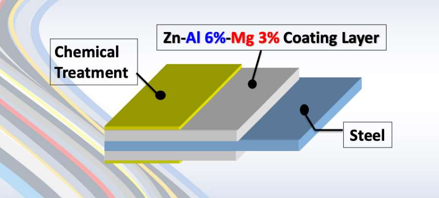
ZAM Coating

ZAM Coating

What is Hot-dip galvanizing? (HDG)?

Hot-dip galvanization is a form of galvanization. It is the process of coating iron and steel with zinc, which alloys with the base metal surface when immersing the metal in a bath of molten zinc at a temperature of around 450 °C (842 °F). When exposed to the atmosphere, the pure zinc (Zn) reacts with oxygen (O2) to form zinc oxide (ZnO), which further reacts with carbon dioxide (CO2) to form zinc carbonate (ZnCO3), a usually dull grey, fairly strong material that protects the steel underneath from further corrosion in many circumstances.

Hot-dip Galvanizing

Hot-dip Galvanizing

Main Differences: Zinc-Aluminum-Magnesium (ZAM) vs Hot-dip galvanizing (HDG)

The comparison between zinc-aluminum-magnesium (ZAM) y hot-dip galvanizing (HDG) revolves around their coating composition, corrosion resistance, applications, cost, y environmental impact. Below is a detailed comparison to help understand their differences:

1. Coating Composition

Zinc-Aluminum-Magnesium (ZAM):
ZAM coatings are made of a combination of zinc (Zn), aluminum (Al), y magnesium (Mg). Typically, the composition is about 80-90% Zinc, 5-11% Aluminum, y 1-3% Magnesium. Including aluminum and magnesium gives the coating superior properties compared to zinc alone.

Hot-Dip Galvanizing (HDG):
HDG involves immersing steel into a molten bath of zinc (Zn) to form a protective zinc coating. The coating consists almost entirely of zinc, with small amounts of iron from the substrate, forming a zinc-iron alloy layer.

2. Resistencia a la corrosión

Zinc-Aluminum-Magnesium (ZAM):
Superior corrosion resistance compared to hot-dip galvanized steel. Adding aluminum increases the coating’s resistance to high temperatures and oxidation, while magnesium improves its resistance to corrosion in harsh environments like coastal, industrial, and chemical settings. ZAM has self-healing properties—if the coating is damaged, the magnesium component reacts with moisture to help prevent further corrosion.

Hot-Dip Galvanizing (HDG):
It provides good corrosion resistance but not as high as ZAM, especially in aggressive environments. The zinc coating is sacrificial, meaning it corrodes first to protect the underlying steel, but its effectiveness can be limited in humid, salty, o chemical environments. HDG does not have the advanced self-healing properties that ZAM offers.

3. Durability and Longevity

Zinc-Aluminum-Magnesium (ZAM):
ZAM-coated products can last 2 to 4 times longer than traditional galvanized steel in harsh environments (e.g., coastal areas, chemical plants, etc.). The coating’s enhanced resistance to environmental factors contributes to a longer service life.

Hot-Dip Galvanizing (HDG):
The lifespan of HDG products is good but generally shorter than ZAM, particularly in extreme conditions. HDG can last for many years in less corrosive environments (e.g., mild climates), but its protection may degrade faster in severe environments.

4. Applications

Zinc-Aluminum-Magnesium (ZAM):
Ideal for entornos hostiles such as Coastal areas (where saltwater exposure is high), Chemical and industrial environments (where exposure to aggressive substances is every day), Solar panel mounts (due to its superior durability), Heavy-duty industrial applications (e.g., agricultural and mining equipment, steel structures exposed to extreme weather conditions).

Hot-Dip Galvanizing (HDG):
It is commonly used in general construction, automotive industries, outdoor infrastructure, y agricultural applications. It is suitable for general-purpose corrosion protection in outdoor conditions but not recommended for extreme or coastal environments.

5. Cost

Zinc-Aluminum-Magnesium (ZAM):
It is more expensive than traditional hot-dip galvanizing due to the inclusion of aluminum and magnesium and the more advanced coating process. The longer lifespan and lower maintenance costs in harsh environments often justify the higher initial cost.

Hot-Dip Galvanizing (HDG):
It is cheaper than ZAM, making it more suitable for projects where cost-efficiency is a priority and the environment is less aggressive. The relatively lower cost makes it ideal for large-scale production.

6. Environmental Impact

Zinc-Aluminum-Magnesium (ZAM):
The production of ZAM coatings is more environmentally friendly than hot-dip galvanizing, as it involves lower emissions of harmful gases and waste materials. The production process for ZAM generally generates less waste y fewer harmful emissions compared to traditional galvanizing methods.

Hot-Dip Galvanizing (HDG):
It is more environmentally intensive than ZAM, producing more waste gases and wastewater. However, modern improvements in the HDG process have aimed to reduce the environmental footprint, though it remains higher than ZAM.

7. Aesthetic Appearance

Zinc-Aluminum-Magnesium (ZAM):
ZAM has a matte gray finish with a smoother, more uniform appearance. This appearance can be more desirable in specific applications like architectural structures or solar panel mounts.

Hot-Dip Galvanizing (HDG):
HDG often has a shiny or dull metallic finish, depending on the thickness of the coating. While durable, its aesthetic appearance may be less appealing than ZAM’s, especially if the finish is uneven.

8. Ease of Processing and Welding

Zinc-Aluminum-Magnesium (ZAM):
ZAM coatings can be more challenging to process, weld, y paint than traditional galvanized steel, creating issues in some applications.

Hot-Dip Galvanizing (HDG):
HDG products are easier to weld and process than ZAM. However, the zinc coating can make welding and cutting more difficult due to zinc fumes, and special precautions may be required.

Summary Comparison Table: Zinc-Aluminum-Magnesium (ZAM) vs Hot-dip Galvanizing (HDG)

Característica Zinc-Aluminum-Magnesium (ZAM) Hot-Dip Galvanizing (HDG)
Coating Composition Zinc, Aluminum, Magnesium Zinc (with some iron from the substrate)
Resistencia a la corrosión Superior, especially in harsh environments Good, but less effective in aggressive settings
Durability and Longevity 2-4 times longer than HDG in extreme environments Moderate lifespan, shorter in harsh conditions
Aplicaciones Coastal areas, chemical environments, heavy-duty General outdoor infrastructure, agriculture
Costo Higher initial cost Lower initial cost
Impacto medioambiental Lower emissions and waste Higher emissions and waste
Aesthetic Appearance Matte gray, smoother finish Shiny or dull metallic finish
Ease of Processing It can be more challenging, especially with welding It is more straightforward to process and weld

Conclusión

ZAM is the best choice for extreme environments where superior corrosion resistance and durability are needed. Its long-term performance can justify the higher upfront cost.

HDG remains the go-to solution for general corrosion protection in less aggressive environments, providing a cost-effective and widely available option for most standard applications.

Pipeline vs Piping

Tuberías y ductos terrestres y marinos

Introducción

In the realm of energy transportation, the distinction between onshore and offshore pipelines and piping systems plays a crucial role in the efficiency, safety, and environmental impact of resource extraction and distribution. Onshore pipelines, typically situated on land, are designed to transport oil, gas, and other fluids over varying distances, benefiting from relatively more straightforward access for maintenance and monitoring. Conversely, offshore pipelines, laid on the seabed or suspended in water, present unique engineering challenges due to harsh marine conditions and logistical complexities. Understanding the Onshore vs Offshore Pipeline and Piping in design, construction, and operational considerations between these two types of pipelines is essential for optimizing infrastructure development and ensuring sustainable practices in the energy sector.

Definition: Onshore vs Offshore Pipeline and Piping

What is Pipeline?

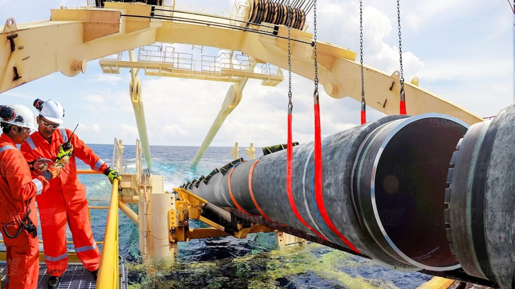
Pipeline is a long series of pipes, usually of large diameter, running underground, aboveground and underwater, such as a submarine pipeline, and equipped with fittings, such as valves and pumps, to control the flow of large quantities of fluid over long distances. Pipelines have large diameters, making it easy to transport liquids or gases in bulk from one place to another, sometimes for thousands of miles.

Pipeline

Pipeline

What is Piping?

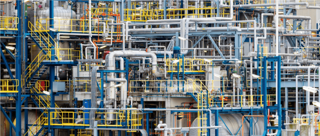
Tubería is a system of pipes used to convey fluids (liquids and gases) from one location to another within the designated boundaries or spaces of petrochemical plants, power plants, refineries, etc. It is also equipped with valves and fittings to control the flow of fluids from one facility to another as needed, but only within the plant’s designated boundaries. Never skip these essential topics when taking an online course on piping engineering. Piping diameters range from 1/2 inch to 80 inches, depending on the facility’s design requirements for fluid transportation, usually from one facility to another within the facility’s boundaries.

Tubería

Tubería

What is Onshore Pipeline?

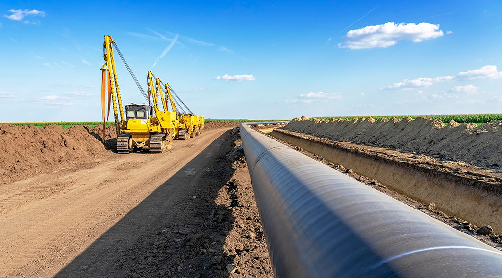
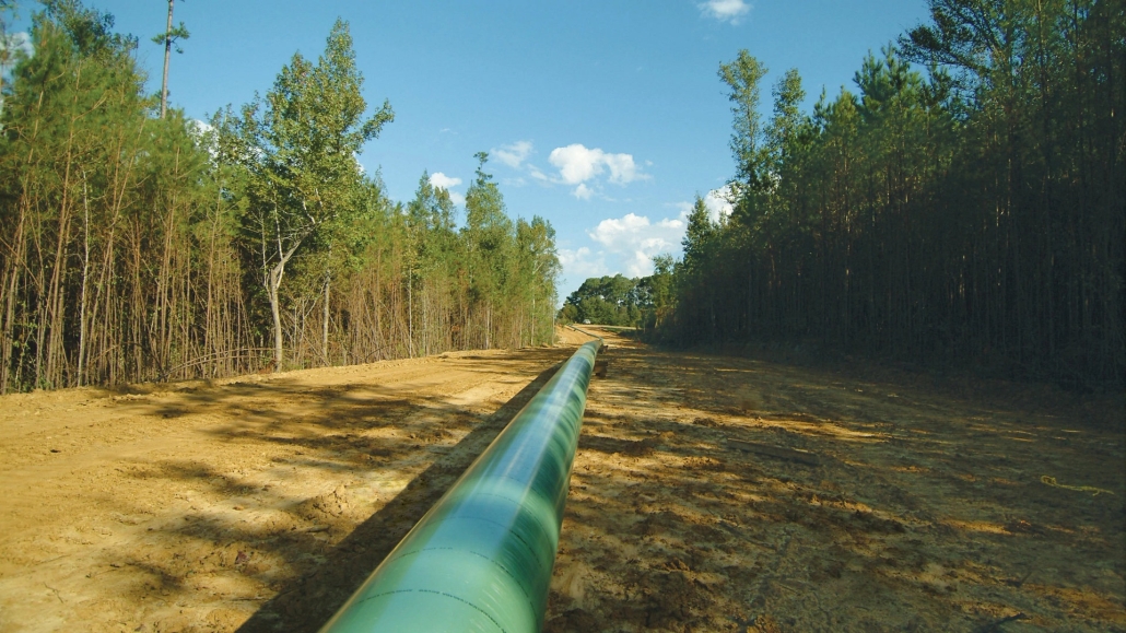
Onshore pipelines refer to networks of pipelines and related equipment used to transport fluids such as oil, natural gas, water, and chemicals in a land environment. These pipelines are integral to long-distance oil and gas transportation from oil fields to refineries, from natural gas wells to gas stations, and from crude oil and refined oil tank farms, chemical tank farms, LNG tank farms, and aircraft refueling pipeline operations.

Onshore Pipeline

Onshore Pipeline

What is Offshore Pipeline?

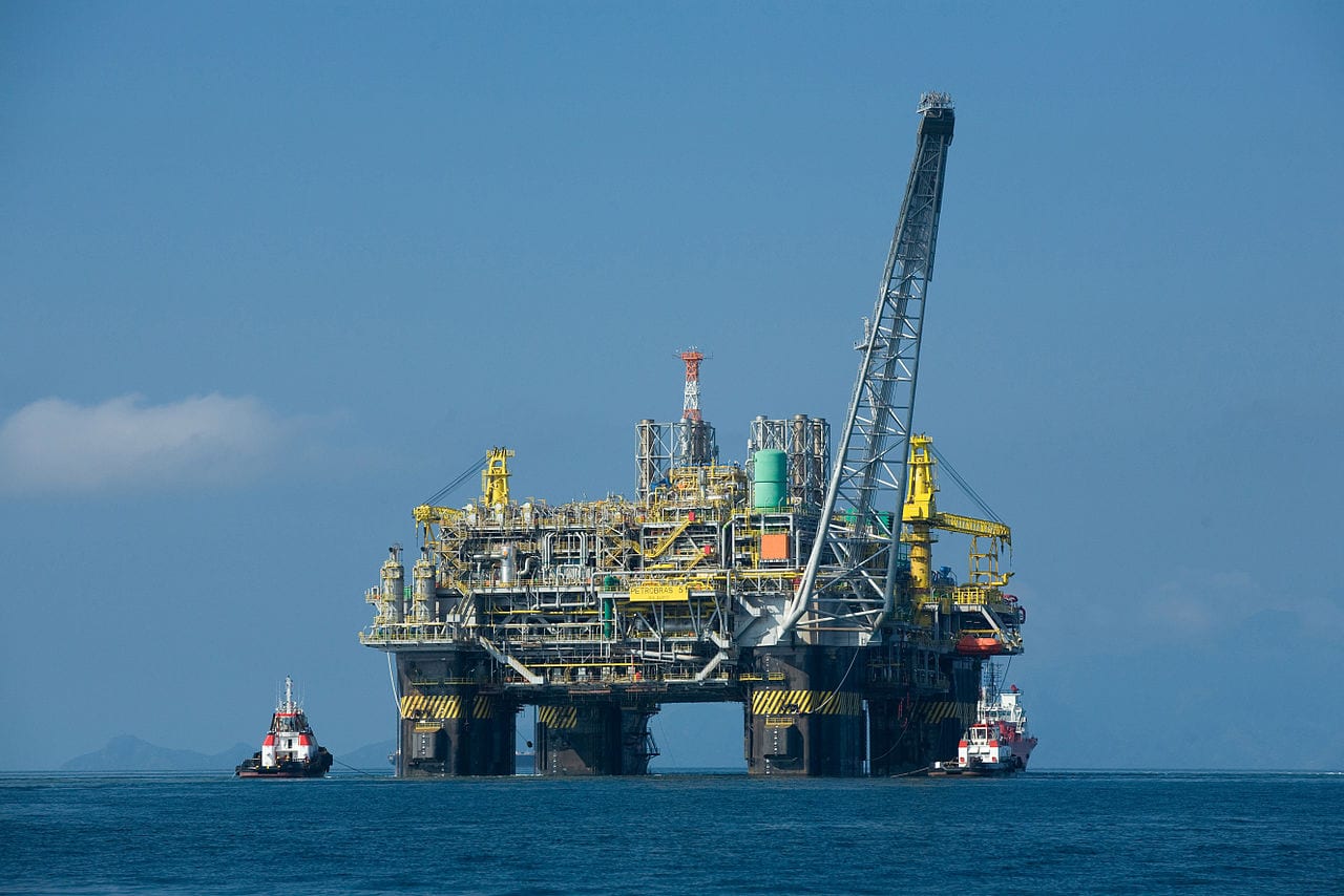
Offshore pipelines refer to the network of pipes and related equipment used to transport fluids such as oil, gas, water, and chemicals in an offshore environment. These pipelines are integral to operating offshore oil rigs, platforms and floating production storage and offloading units (FPSOs). The unique conditions of the offshore environment, such as high salinity, extreme temperatures, and strong currents, present significant challenges to the design and maintenance of these systems.

Offshore Pipeline

Offshore Pipeline

Main Differences: Onshore vs Offshore Pipeline and Piping

Comparison Table: Onshore vs Offshore Pipeline and Piping

Especificación En tierra Costa afuera
Pipeline Tubería Pipeline Tubería
Códigos de diseño – ASME B31.4: Pipeline Transportation Systems for Liquids and Slurries
– ASME B31.8: Gas Transmission and Distribution Piping Systems
ASME B31.3: Process Piping – DNVGL-ST-F101: Submarine pipeline systems
– API RP 1111: Design, Construction, Operation, and Maintenance of Offshore Hydrocarbon Pipelines (Limit state design)
ASME B31.3: Process Piping
Alcance Outside plant boundary
(Villages, fields, rivers, canals, railways, highways, cities, deserts, forests, hills, etc.)
Within plant boundary Outside plant boundary Within plant boundary
Type of pipe API Spec 5L: Specification for Line pipes – ASTM
– BS
– API 5L
API Spec 5L: Specification for Line pipes
– DNVGl-ST-F101: Submarine Pipeline Systems
Normas ASTM
Válvulas – API 6D: Specification for Pipeline and Piping Valves
– Full Bore (FB) Ball Valves are used for pigs.
– BS
– API Standard
– Full bore (FB) and Reduced bore (RB)
– Full bore Valves: for smooth passage of intelligent pigs
– API 6D SS: Specification on Subsea Pipeline Valves
– RB valves
– BS/API standards
Soldadura – API Std. 1104: Welding of Pipelines and Related Facilities
– Type of welding: Automatic / Semi-Automatic/ Manual
– ASME Sec. IX: Standard for Welding and Brazing Procedures, Welders, Brazers and Welding and Brazing Operators
– Type of welding: Manual (mostly)
– API Std. 1104: Welding of Pipelines and Related Facilities
– Mostly automatic welding on pipelay barge.
– ASME Sec. IX: Standard for Welding and Brazing Procedures, Welders, Brazers and Welding and Brazing Operators
– Manual welding at the fabrication yard.
Weld joint inspection (NDT requirements) 100% by Automatic UT or RT (by using X-Ray) 5% to 100%
(mostly by using gamma rays)
100% by Automatic UT From 10% to 100% as required
Analyses – Wall Thickness Analysis
– Elastic Bend Radius Analysis
– Stability Analysis for Water Bodies/ Marshy Areas
– Horizontal directional drilling design analysis
– Railroad/ Highway Crossing Analysis
– Casing Pipe Analysis for Crossings
– Seismic Analysis
– Piping wall thickness calculation
– Piping Stress Analysis
Static Analysis
Dynamic Analysis
Wind Analysis
Flange Leakage Analysis
Seismic Analysis
– Wall thickness Analysis
– On-bottom Stability
– Span Analysis
– Global Buckling – Lateral and Upheaval
– Pipeline Expansion Analysis
– Riser Design (Span, Stress & Flexibility Analysis)
– Riser Clamp Design
– Pipeline Crossing Design and Analysis
– Deck piping stress analysis
Instalación Buried (mostly) Above ground/On rack/slippers/T-postal etc. Subsea (in water on the seabed or buried in the seabed) Deck Platform Piping
(similar to plant)
Special Installations – Across rivers
– Horizontal Directional Drilling (HDD) method
– Micro-tunnelling method
– Across road/ rail/ highway
– Auger boring/ jacking boring method
– Shallow HDD
– Ghats/ Hills
– Modular installations
– Finning
– Studding
– Jacketing
– Spooling inside warehouse
– U/G piping for cooling water
– S-lay Method (for shallow water installation)
– J-Lay Method (for deep water installation)
– Shore pull/ barge pull near Land Fall Point (LFP)
Along with the deck structure
Special Equipment – Sectionalizing Valves (Remote operated)
– Insulating Joints
– Scraper Launcher/ Receiver
– Stem Extended Valves (for buried valves)
– Flow Tee
– Long Radius bends (R=6D)
– Cold field bends (R = 30D or 40D)
– Expansion Joints
– Motor Operator Valves (MOV)
– Cryogenic Valves
– Springs
– Subsea Isolation Valve (SSIV)
– LR Bends
– Flow tee
– Pipeline End Manifold (PLEM)
– Single Point Mooring (SPM) system
– Submarine hoses
– Floating hoses
– Cables and umbilical installation
– Piggy-back pipelines
No aplicable
Survey – Topographical Survey
(all along the pipeline route)
– Geotechnical investigation
(all along the pipeline route)
– Soil resistivity survey
(all along the pipeline route)
– Hydrological Survey for water bodies (for scour depth calculation)
– Cadastral Survey (for RoU acquisition)
– Wind profile from meteorology
– Seismic study of plot
– Geophysical survey/ Bathymetric Survey by using side scan sonar, sub-bottom profiler, and echo-sounder
– Met-Ocean data collection
– Geotechnical data of the pipeline route
No aplicable
Corrosion Protection Coating Three Layer Polyethylene (3LPE) coating
Three Layer Polypropylene (3LPP) coating
Fusion bonded epoxy (FBE) coating
– Coal tar enamel (CTE) Coating
Painting Coatings such as:
– Coal Tar Enamel Coating (CTE)
Three-layer polyethylene coating (3LPE)
Three-layer polypropylene coating (3LPP)
– Double-layer fusion bonded epoxy coating (2FBE)
Painting
Cathodic Protection System – Impressed Current Cathodic Protection (ICCP) system
– Sacrificial Anode (limited locations)
Not applicable Sacrificial Anodic Cathodic Protection (SACP) system No aplicable
Hydrostatic testing – Gauge Plate run of 95% of the ID of the highest pipe thickness
– Test Pressure
Minimum: 1.25 times of Design Pressure (for liquid pipelines)
1.25 to 1.5 times of Design Pressure (for gas pipelines)
Maximum: Pressure equivalent to Hoop stress of 95% of SMYS of pipe material
– Hold period: 24 hours
– No gauge plate run is done. Generally, cardboard blasting is done to clean the piping.
– Test Pressure
Minimum: 1.5 × Design Pressure × Temperature Factor
Maximum: Based on line schedule
– Hold period: 2 – 6 hours
– Gauge Plate run of 95% of the ID of the highest pipeline thickness.
– Test Pressure
Minimum: 1.25 times x Design Pressure
– Hold period: 24 hours
– No gauging is done.
– Test Pressure
Maximum: As per line schedule
– Hold period: 2 hours
Preservation – Preservation of pipeline with corrosion-inhibited water or by filling of inert gas (N2) Not applicable
Pigging Intelligent Pigging Not applicable Compliant Not applicable
Machines/Equipment required for installation – Trencher
– Backhoe/ Excavator
– Side Boom
– Cold field bending machine
– Holiday Detection Machines
– Pneumatic/ Hydraulic Internal Clamps
Crane/ Hydra – Pipelay Barge
– Derrick Barge
– Diving support vessel
– Dynamic Positioning (DP) barge (for deepwater)
Pre-fabricated deck piping

Conclusion: Onshore vs Offshore Pipeline and Piping

In summary, Onshore pipelines are usually buried or erected on land to transport oil, natural gas, drinking water, sewage, seawater, slurry, etc. Onshore piping is typically erected in petrochemical plants, power plants, refineries, fire protection systems, water treatment systems, etc., while Offshore pipelines are buried on the seabed. Offshore piping typically consists of transmission and structural support pipeline systems on offshore drilling platforms. Special offshore equipment includes underwater isolation valves, tees, and submarine hoses. Offshore surveys include geophysics, bathymetry, and ocean data collection, while onshore surveys focus on topographic and geotechnical engineering studies.

L80-9Cr vs L80-13Cr

L80-9Cr vs L80-13Cr: algo que debes saber

Choosing the proper casing and tubing materials can ensure safety and efficiency in oil and gas drilling and exploration. L80-9Cr and L80-13Cr are two alloy steel grades commonly used in petroleum casing and tubing. Each grade has unique characteristics and applications. L80-9Cr vs L80-13Cr, this article will delve into the difference between these materials to help you make an informed decision.

1. Overview of L80 Grade

L80 is an alloy steel used in the oil and gas sector. It is known for its good strength and corrosion resistance. It is typically employed in high-temperature and high-pressure environments and is suitable for both oil and gas production.

1.1 L80-9Cr

Composition: Contains 9% chromium, enhancing the material’s oxidation resistance at high temperatures.
Características:
Corrosion Resistance: It performs well in CO2 environments, making it suitable for acidic gas pipelines.
Mechanical Strength: Provides good strength and is suitable for high-temperature operations.
Applications: Commonly used in high-temperature gas pipelines in oil fields.

1.2 L80-13Cr

Composition: Contains 13% chromium, offering higher corrosion resistance.
Características:
Corrosion Resistance: Exhibits superior performance in environments with H2S and CO2, suitable for extreme conditions.
Mechanical Strength: Offers higher strength and is ideal for complex operational environments.
Applications: Used in high-corrosion environments and deep well operations.

L80-9Cr vs L80-13Cr

L80-9Cr and L80-13Cr Casing and Tubing in Oil and Gas Drilling and Exploration

2. Comparison: L80-9Cr vs L80-13Cr

2.1 Chemical Composition

Estándar Calificación C Si Minnesota PAG S cr Mes Ni Cu
API 5CT L80-9Cr ≤ 0,15 ≤ 1.00 0.30-0.60 ≤ 0,020 ≤ 0,010 8.00-10.00 0.90-1.10 ≤ 0.50 ≤ 0,25
L80-13Cr 0.15-0.22 ≤ 1.00 0.25-1.00 ≤ 0,020 ≤ 0,010 12.00-14.00 ≤ 0.50 ≤ 0,25

2.2 Propiedades mecánicas

Estándar Calificación Yield Strength (Mpa) Resistencia a la tracción (Mpa) Elongación (%) Hardness max
mín. max. mín. mín. CDH HBW
API 5CT L80-9Cr 552 655 655 API 5CT
Table C.7
23 241
L80-13Cr 552 655 655 23 241

2.3 Impact Test

Estándar Calificación Sharpy Impact Energy (J)
Coupling Cuerpo de tubería
API 5CT L80-9Cr L-10-40-0 T-10-20-0 L-10-27-0 T-10-14-0
L80-13Cr L-10-40-0 T-10-20-0 L-10-27-0 T-10-14-0

2.4 Corrosion Resistance

L80-9Cr: The 9% chromium content provides moderate corrosion resistance, suitable for environments with low to moderate concentrations of H₂S (hydrogen sulfide) or CO₂ (carbon dioxide), typically seen in less aggressive environments.

L80-13Cr: The 13% chromium content provides enhanced resistance to sour service (i.e., environments with high levels of H₂S) and high CO₂ environments. It’s better for harsher conditions like deep wells or offshore drilling.

2.5 Temperature and Sour Service

L80-9Cr: Generally suitable for moderate-temperature environments.

L80-13Cr: Can withstand higher temperatures and is better equipped for sour service conditions with high concentrations of H₂S or CO₂.

2.6 Cost

L80-9Cr: Due to its lower chromium content, L80-9Cr is less expensive than L80-13Cr. If the environment is not highly corrosive or sour, L80-9Cr could be a more cost-effective option.

L80-13Cr: More expensive but provides superior resistance in harsh conditions, potentially reducing maintenance costs or failures over time.

2.7 Applications

L80-9Cr: Suitable in wells with moderate temperature, pressure, and sour gas conditions. Often used in conventional oil and gas wells or less aggressive service environments.

L80-13Cr: Ideal for high-pressure wells with harsh environmental conditions, particularly in sour gas service, deep wells, or offshore oil & gas operations where high corrosion resistance is critical.

Turbinas eólicas marinas

Perfiles huecos circulares estructurales para aerogeneradores terrestres y marinos

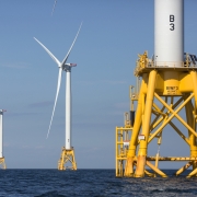
A medida que la demanda de energía renovable continúa aumentando a nivel mundial, la energía eólica marina se ha convertido en una solución vital. Este artículo analiza en profundidad la importancia de los perfiles huecos circulares estructurales (CHS) utilizados en las estructuras de soporte de las turbinas eólicas marinas, explorando su diseño, propiedades de los materiales y aplicaciones.

1. Comprensión de las secciones huecas circulares estructurales

Perfiles huecos circulares estructurales Son tubos cilíndricos con un centro hueco. Estas secciones desempeñan un papel crucial en las estructuras de soporte de las turbinas eólicas marinas, que están diseñadas principalmente para soportar el peso de la turbina y resistir las presiones ambientales externas.

2. Propiedades materiales de los perfiles huecos circulares estructurales

Acero al carbono: S355MH, S355MLH, S420MH, S420MLH, S460MH, S460MLH, S460QH, S460QLH, S620QH, S620QLH, S690QH, S690QLH

3. Consideraciones de diseño

A la hora de diseñar estructuras de soporte para turbinas eólicas marinas hay que tener en cuenta varios factores:
Carga de viento: Las turbinas experimentan cargas dinámicas del viento durante su funcionamiento, lo que requiere un diseño que garantice la estabilidad estructural.
Impacto de las olas: Las olas en ambientes marinos ejercen una presión adicional sobre las estructuras, lo que requiere cálculos cuidadosos y ajustes de diseño.
Protección contra la corrosión: Dada la naturaleza corrosiva del agua de mar, el uso de recubrimientos protectores o materiales resistentes a la corrosión es esencial para prolongar la vida útil de la estructura.

4. Ventajas de utilizar perfiles huecos circulares

El uso de perfiles huecos circulares en estructuras de soporte ofrece varias ventajas:
Alta resistencia a la compresión: la sección transversal circular permite una distribución uniforme de la presión, mejorando la estabilidad general.
Ligero: En comparación con otras formas, los tubos circulares proporcionan una resistencia similar con un peso reducido, lo que facilita el transporte y la instalación.
Facilidad de construcción: La simplicidad de conectar y soldar tubos circulares aumenta la eficiencia de la construcción.

5. Preguntas frecuentes

P: ¿Qué material se debe elegir para los perfiles huecos circulares estructurales?
A: La elección del material depende de las condiciones ambientales específicas, el presupuesto y los requisitos de diseño. El acero al carbono es adecuado para la mayoría de las aplicaciones, pero en entornos altamente corrosivos, el acero inoxidable o el acero aleado pueden ser más apropiados.

P: ¿Cómo se puede garantizar la durabilidad de los perfiles huecos circulares estructurales?
A: Las inspecciones y el mantenimiento periódicos son fundamentales para garantizar la durabilidad. Además, la selección de revestimientos y materiales protectores adecuados puede prolongar significativamente la vida útil de las estructuras.

6. Conclusión

Los perfiles huecos circulares estructurales son indispensables en las estructuras de soporte de las turbinas eólicas marinas. Mediante un diseño cuidadoso y una selección de materiales, las turbinas eólicas pueden mejorar su estabilidad y durabilidad, impulsando así el desarrollo de las energías renovables.

Para más consultas o asistencia sobre perfiles huecos estructurales para estructuras de turbinas eólicas terrestres y marinas, no dude en comunicarse con nosotros en [email protected].

Producción de acero crudo

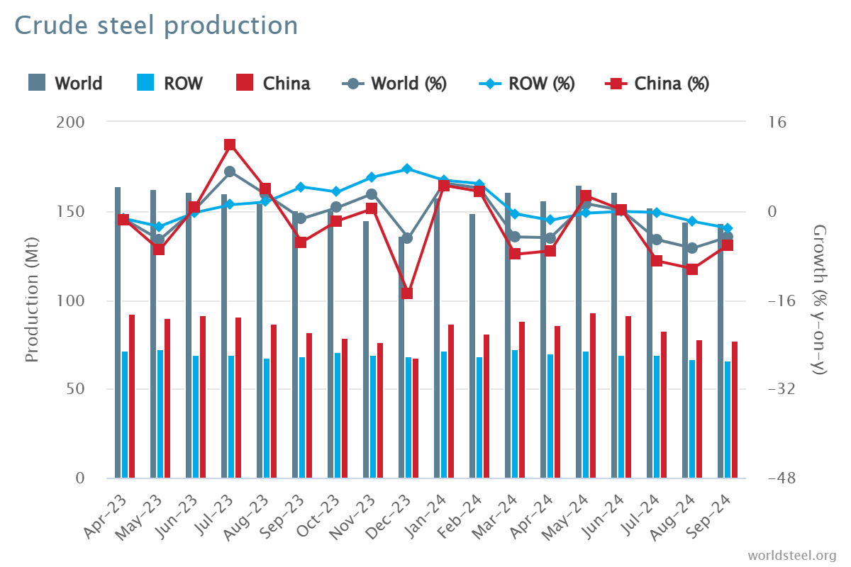
Producción de acero crudo en septiembre de 2024

En septiembre de 2024, la producción mundial de acero crudo de los 71 países que informan a la Asociación Mundial del Acero (acero mundial) fue de 143,6 millones de toneladas (Mt), una disminución de 4,7% respecto de septiembre de 2023.

producción de acero crudo

producción de acero crudo

Producción de acero crudo por regiones

África produjo 1,9 Mt en septiembre de 2024, 2,61 TP3T más que en septiembre de 2023. Asia y Oceanía produjeron 105,3 Mt, 5,01 TP3T menos. La UE (27) produjo 10,5 Mt, 0,31 TP3T más. Europa, Otros produjo 3,6 Mt, 4,11 TP3T más. Oriente Medio produjo 3,5 Mt, 23,01 TP3T menos. América del Norte produjo 8,6 Mt, 3,41 TP3T menos. Rusia y otros países de la CEI + Ucrania produjeron 6,8 Mt, 7,61 TP3T menos. América del Sur produjo 3,5 Mt, 3,31 TP3T más.

Cuadro 1. Producción de acero crudo por regiones

Región septiembre 2024 (mt) Cambio de % 24/23 de septiembre Enero-septiembre de 2024 (Mt) % cambio enero-septiembre 24/23
África 1.9 2.6 16.6 2.3
Asia y Oceanía 105.3 -5 1,032.00 -2.5
UE (27) 10.5 0.3 97.8 1.5
Europa, Otros 3.6 4.1 33.1 7.8
Oriente Medio 3.5 -23 38.4 -1.5
América del norte 8.6 -3.4 80 -3.9
Rusia y otros países de la CEI + Ucrania 6.8 -7.6 64.9 -2.5
Sudamerica 3.5 3.3 31.4 0
Total 71 países 143.6 -4.7 1,394.10 -1.9

Los 71 países incluidos en esta tabla representaron aproximadamente 98% de la producción mundial total de acero crudo en 2023.

Regiones y países cubiertos por la tabla:

  • África: Argelia, Egipto, Libia, Marruecos, Sudáfrica, Túnez
  • Asia y Oceanía: Australia, China, India, Japón, Mongolia, Nueva Zelanda, Pakistán, Corea del Sur, Taiwán (China), Tailandia, Vietnam
  • Unión Europea (27): Alemania, Austria, Bélgica, Bulgaria, Croacia, Eslovaquia, Eslovenia, España, Finlandia, Francia, Grecia, Hungría, Italia, Luxemburgo, Países Bajos, Polonia, Portugal, República Checa, Rumanía y Suecia.
  • Europa, Otros: Macedonia, Noruega, Serbia, Turquía, Reino Unido
  • Oriente Medio: Arabia Saudita, Bahréin, Emiratos Árabes Unidos, Irak, Irán, Jordania, Kuwait, Omán, Qatar, Yemen
  • América del norte: Canadá, Cuba, El Salvador, Guatemala, México, Estados Unidos
  • Rusia y otros países de la CEI + Ucrania: Bielorrusia, Kazajstán, Rusia, Ucrania
  • Sudamerica: Argentina, Brasil, Chile, Colombia, Ecuador, Paraguay, Perú, Uruguay, Venezuela

Los 10 principales países productores de acero

China produjo 77,1 Mt en septiembre de 2024, 6,11 TP3T menos que en septiembre de 2023. India produjo 11,7 Mt, 0,21 TP3T menos. Japón produjo 6,6 Mt, 5,81 TP3T menos. Estados Unidos produjo 6,7 Mt, 1,21 TP3T más. Se estima que Rusia produjo 5,6 Mt, 10,31 TP3T menos. Corea del Sur produjo 5,5 Mt, 1,31 TP3T más. Alemania produjo 3,0 Mt, 4,31 TP3T más. Turquía produjo 3,1 Mt, 6,51 TP3T más. Brasil produjo 2,8 Mt, 9,91 TP3T más. Se estima que Irán produjo 1,5 Mt, 41,21 TP3T menos.

Cuadro 2. Los 10 principales países productores de acero

Región  septiembre 2024 (mt) Cambio de % 24/23 de septiembre Enero-septiembre de 2024 (Mt) % cambio enero-septiembre 24/23
Porcelana 77.1 -6.1 768.5 -3.6
India 11.7 -0.2 110.3 5.8
Japón 6.6 -5.8 63.3 -3.2
Estados Unidos 6.7 1.2 60.3 -1.6
Rusia 5.6e -10.3 54 -5.5
Corea del Sur 5.5 1.3 48.1 -4.6
Alemania 3 4.3 28.4 4
Turquía 3.1 6.5 27.9 13.8
Brasil 2.8 9.9 25.2 4.4
Irán 1,5 e -41.2 21.3 -3.1

e – estimado. La clasificación de los 10 principales países productores se basa en el agregado del año hasta la fecha.

Comparación entre API 5L y ISO 3183

Conozca las diferencias: API 5L vs ISO 3183

Las normas ISO 3183 y API 5L son normas relacionadas con las tuberías de acero, principalmente para su uso en las industrias de transporte de petróleo, gas y otros fluidos. Si bien existe una superposición significativa entre estas dos normas, API 5L e ISO 3183, existen diferencias clave en su alcance, aplicación y las organizaciones que las respaldan.

1. Organismos emisores: API 5L vs ISO 3183

API 5L: Emitida por el Instituto Americano del Petróleo (API), esta norma se utiliza principalmente en la industria del petróleo y el gas. Detalla los requisitos técnicos para las tuberías de acero que transportan petróleo, gas y agua.
ISO 3183: Emitida por la Organización Internacional de Normalización (ISO), esta norma es reconocida internacionalmente y utilizada globalmente para tuberías de acero en el sector de transporte de petróleo y gas.

2. Ámbito de aplicación: API 5L vs ISO 3183

API 5L: Cubre tuberías de acero para transportar petróleo, gas natural y otros fluidos a alta presión. Es ampliamente utilizada en América del Norte, especialmente en Estados Unidos.
ISO 3183: Esta norma se centra principalmente en el diseño, fabricación y control de calidad de las tuberías de acero utilizadas en oleoductos y gasoductos, pero su uso es más internacional y aplicable en varios países del mundo.

3. Diferencias clave: API 5L vs ISO 3183

Enfoque geográfico y de mercado:

API 5L está más adaptada al mercado norteamericano (particularmente EE. UU.), mientras que ISO 3183 es aplicable internacionalmente y se utiliza en muchos países del mundo.

Grados y requisitos del acero:

API 5L define grados de acero como L175, L210, L245, etc., donde el número representa la resistencia mínima al rendimiento en megapascales (MPa).
La norma ISO 3183 también define grados similares pero con requisitos más detallados respecto a las propiedades del material, los procesos de fabricación y los protocolos de inspección, alineándose con las prácticas industriales internacionales.
Especificaciones adicionales:
API 5L enfatiza el control de calidad, la certificación y los requisitos de producción, mientras que ISO 3183 cubre un alcance más amplio, teniendo en cuenta el comercio internacional, y proporciona especificaciones para diferentes condiciones, incluida la temperatura, el medio ambiente y los requisitos mecánicos específicos.

4. Requisitos técnicos: API 5L vs ISO 3183

La API 5L especifica las propiedades de los materiales, los procesos de fabricación, las dimensiones, los métodos de prueba y el control de calidad de las tuberías de acero. Define los grados de acero desde L (baja resistencia) hasta X (mayor resistencia), como X42, X60 y X70.
La norma ISO 3183 cubre aspectos similares de la fabricación de tuberías de acero, incluida la calidad del material, el tratamiento térmico, el tratamiento de la superficie y los extremos de las tuberías. También proporciona especificaciones detalladas para la presión de diseño de las tuberías, consideraciones ambientales y diversos accesorios para tuberías.

5. Comparación de grados de tuberías: API 5L vs ISO 3183

API 5L: Los grados van desde los grados L (resistencia a la fluencia baja) hasta los grados X (resistencia a la fluencia más alta). Por ejemplo, X60 se refiere a tuberías con una resistencia a la fluencia de 60 000 psi (aproximadamente 413 MPa).
ISO 3183: Utiliza un sistema de clasificación similar, pero puede incluir clasificaciones y condiciones más detalladas. También garantiza la alineación con las prácticas operativas y de diseño de tuberías globales.

6. Compatibilidad entre normas:

En muchos casos, API 5L e ISO 3183 son compatibles, lo que significa que una tubería de acero que cumple con los requisitos de API 5L generalmente también cumplirá con los requisitos de ISO 3183 y viceversa. Sin embargo, proyectos de tuberías específicos pueden adherirse a una norma en lugar de a otra según la ubicación, las preferencias del cliente o los requisitos regulatorios.

7. Conclusión:

La API 5L es más común en los Estados Unidos y las regiones circundantes. Se centra en la industria de oleoductos y gasoductos, y pone un gran énfasis en la producción y el control de calidad.
La ISO 3183 es una norma internacional para proyectos de oleoductos y gasoductos a nivel mundial. Sus requisitos más detallados y alineados a nivel mundial garantizan una mayor aceptación en los mercados internacionales.

Ambas normas son muy similares en cuanto a especificaciones de materiales, fabricación y pruebas. Aun así, la ISO 3183 tiende a tener un alcance más amplio y de aplicación más global, mientras que la API 5L sigue siendo más específica para el mercado norteamericano. La elección entre estas normas depende de la ubicación geográfica, las especificaciones y las necesidades regulatorias del proyecto de oleoducto.