API 仕様 5DP ドリルパイプ: 総合ガイド
API仕様5DPドリルパイプの紹介
ドリルパイプは石油・ガス産業の重要なコンポーネントであり、掘削作業の根幹を成しています。これらのパイプは掘削装置とドリルビットを接続し、電力と掘削流体を伝達して地表に掘削孔を掘ります。このブログでは、API 仕様 5DP ドリルパイプについて、製造プロセス、タイプ、接続、グレードなどの詳細を説明します。目標は、ドリルパイプを効果的に使用するための複雑な問題に対処するのに役立つ実用的な知識とソリューションを提供することです。
とは API仕様5DPドリルパイプ?
ドリルパイプは、掘削作業中にドリルビットを回転させ、掘削液を循環させる、重くて継ぎ目のない中空の管です。ねじれ、張力、圧力などの大きな応力に耐えられるように設計されており、リグを簡単に扱えるほど軽量です。
ドリルパイプの重要な機能:
- 動力伝達: ドリルパイプは、掘削装置からの回転運動をドリルビットに伝達します。
- 掘削流体の循環: 掘削泥の循環を可能にし、ビットを冷却し、掘削土を地表に運び、掘削孔を安定させます。
- ドリルストリングを長くする: 掘削が進むにつれて、より深いところまで到達できるように、ドリル ストリングにドリル パイプ セクションが追加されます。
API仕様5DPドリルパイプの製造工程
ドリルパイプの製造は、最終製品が掘削作業に必要な厳格な基準を満たすように設計された、高度に管理されたプロセスです。
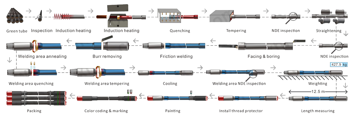
ドリルパイプの製造工程
1. 材料の選択
- 高品質のスチール: このプロセスは、高強度と高靭性で知られる AISI 4130 や 4140 などの合金鋼などの高級鋼を選択することから始まります。
- 化学組成: 鋼の組成は、摩耗、疲労、腐食に対する耐性など、望ましい機械的特性を実現するために慎重に管理されています。
2. パイプ成形
- シームレスな製造: 鋼鉄を加熱して穴を開け、中空の管を作り、これを引き伸ばして巻いてドリルパイプ本体を形成します。
- 溶接(オプション): 特定のタイプでは、鋼板を巻いて溶接し、パイプを作成することもあります。
3. 熱処理
- 焼入れと焼戻し: パイプは熱処理を受けて機械的特性を高め、掘削の過酷な条件に耐えられるようにします。
4. 動揺させる
- 動揺の終わり: パイプの端部は強度を高めるために厚く加工されます。この加工は据え込み加工と呼ばれ、接続部におけるパイプの耐久性を高めるために非常に重要です。
5. ツールジョイント溶接
- ツールジョイントの取り付け: ツールジョイントはパイプの端に溶接され、ドリルストリングの各セクションをリンクする接続を形成します。
6. ハードバンディング
- 耐摩耗コーティング: ツールジョイントには耐摩耗合金が塗布されており、摩耗から保護し、パイプの耐用年数を延ばします。
7. 検査とテスト
- 非破壊検査: 各ドリルパイプは、欠陥がないことを確認するために、超音波検査や磁気粒子検査などの厳格なテストを受けます。
- 寸法検査: パイプは必要な仕様を満たすように測定されます。
8. マーキングとコーティング
- 識別: 各パイプには、グレード、サイズ、製造元などの重要な情報が記されています。
- 保護コーティング: 輸送中および保管中にパイプを保護するために、耐腐食コーティングがパイプに塗布されています。
API仕様5DPドリルパイプの種類
ドリルパイプにはいくつかの種類があり、それぞれ特定の用途向けに設計されています。
1. 標準ドリルパイプ
- 説明: 標準的な掘削作業に使用される最も一般的なタイプのドリルパイプ。
- 応用: 陸上および海上環境での従来の掘削に適しています。
2. 重量ドリルパイプ(HWDP)
- 説明: HWDP は標準のドリルパイプよりも厚く重いため、ドリルストリングに重量を追加して座屈を減らし、安定性を向上させるように設計されています。
- 応用: 方向性掘削や長距離掘削井に最適です。
3. スパイラルドリルパイプ
- 説明: 掘削時の摩擦と摩耗を軽減する螺旋溝を特徴とするタイプです。
- 応用: 摩擦の低減が重要な操作に使用されます。
4. 角型ドリルパイプ
- 説明: あまり一般的ではないが、断面が四角いタイプで、剛性が増しています。
- 応用: 剛性ドリルストリングを必要とする特定の掘削シナリオで使用されます。
5. 六角ドリルパイプ
- 説明: 角型ドリルパイプに似ていますが、断面が六角形になっており、ねじり強度が向上しています。
- 応用: 高トルクの掘削作業に適しています。
API 仕様 5DP ドリルパイプの終了プロセスとは何ですか?
ドリルパイプの文脈では、 IU, 欧州連合、 そして 国際連合 ドリルパイプの端部を接続用に準備するさまざまな端部処理を指します。これらの処理は、ドリルパイプの端部が耐久性があり、適切に位置合わせされ、ドリルストリング内の他のコンポーネントへのねじ込みや接続に適していることを確認するために重要です。
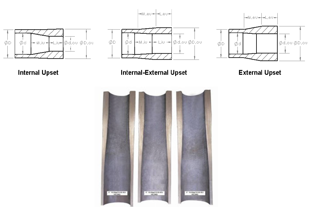
ドリルパイプ端部のIU EU IEU
1. 内部不調(IU)
- 説明: 内部圧縮 (IU) プロセスでは、パイプの内径が縮小され、パイプの端の壁が厚くなります。
- 目的: この厚みによりパイプの端部の強度が増し、掘削作業中に発生する応力や摩耗に対する耐性が向上します。
- 応用: IU パイプは、一定の穴径を維持することが不可欠な高圧掘削作業など、ドリルパイプの内径が重要な状況で使用されます。
2. 外部からの動揺(EU)
- 説明: 外部アップセット (EU) では、パイプの端部の外径部分でパイプ壁の厚さが増加します。
- 目的: このプロセスにより、特にドリルパイプが摩耗や衝撃を受ける可能性が最も高い領域で、パイプの端部が強化され、耐久性が向上します。
- 応用: EU ドリルパイプは、外部強度と耐衝撃性が優先される標準的な掘削作業でよく使用されます。
3. 内部-外部アップセット (IEU)
- 説明: 内部-外部アプセット (IEU) は、内部アプセットと外部アプセットを組み合わせたもので、パイプの端が内部と外部で厚くなります。
- 目的: この二重の厚み付けプロセスにより、ドリルパイプの端部の強度と耐久性が最大限に高まり、内部および外部の力に対する耐性が向上します。
- 応用: IEU パイプは通常、深井戸、高圧シナリオ、方向性掘削など、内部および外部の補強が必要な、より要求の厳しい掘削環境で使用されます。
API仕様5DPドリルパイプツールジョイントの接続
ドリル パイプ セクション間の接続は、ドリル ストリングの整合性を維持するために重要です。API 5DP ドリル パイプには、さまざまなタイプの接続があります。
1. 内部フラッシュ(IF)接続
- 説明: 圧力低下と乱流を最小限に抑えるために、フラッシュ内部プロファイルで設計されています。
- 応用: 高圧掘削環境で使用されます。
2. フルホール(FH)接続
- 説明: 流体の流れを改善するために大きなボアを備えており、深い井戸に適しています。
- 応用: 深掘り作業に最適です。
3. API レギュラー (API REG) 接続
- 説明: 堅牢性と使いやすさで知られる標準の接続タイプです。
- 応用: 標準的な掘削作業でよく使用されます。
4. 数値接続(NC)
- 説明: 多くの場合ダブルショルダー設計を特徴とする、高トルク容量を備えたプレミアム接続。
- 応用: 困難な掘削条件に適しています。
API 仕様 5DP ドリルパイプのピンとボックスとは何ですか?
ピンとボックス ドリル パイプ接続の 2 つの補完的な端部を指します。これにより、パイプ セクションを掘削ストリング内で安全に結合できます。この接続システムは、掘削作業中にドリル ストリングの完全性と安定性を維持するために重要です。
ピン
- 説明: ピンは接続のオス端です。先細りでねじ山が切られており、ボックスにねじ込むことができます。
- デザイン: ピンの外側のネジはボックスの内側のネジに合わせて精密にカットされており、しっかりと固定されます。
- 関数: ピンはボックスにしっかりと接続するように設計されており、掘削中に発生する高圧、ねじり力、振動に耐えられる堅牢で漏れのないジョイントを形成します。
箱
- 説明: ボックスは接続のメス側です。ピンを収容するために内部にねじ山も切られています。
- デザイン: ボックスの内部ネジはピンのネジに合わせて精密に機械加工されており、安全でしっかりとした接続を実現します。
- 関数: ボックスはピンを受け取り、掘削作業中にドリルパイプの各セクションが接続され、整列された状態を保つ強固な接続を作成します。
ピンとボックスの接続の重要性
- 構造の完全性: ピンとボックスの接続により、ドリルパイプの各セクションがしっかりと固定され、ドリルストリングの構造的完全性が維持されます。
- 耐圧性: これらの接続は、掘削流体の循環によって生成される高い内部圧力に耐えられるように設計されています。
- 使いやすさ: ピンとボックスの接続は、簡単に組み立ておよび分解できるように設計されており、ドリル ストリングの迅速な変更と調整を容易にします。
アプリケーション
- ドリルパイプ: ピン接続とボックス接続は、標準パイプ、重量パイプ、特殊パイプを含むすべてのドリルパイプに使用されます。
- ツールジョイント: これらの接続は、ドリルパイプのより厚く重い部分であるツールジョイントにも使用され、強度と耐久性が向上します。
グレード、直径、長さの範囲、および用途
ドリルパイプにはさまざまなグレード、直径、長さがあり、それぞれ異なる掘削環境に適しています。
成績
- E-75: 一般的な掘削作業によく使用されます。
- X-95: より高い強度を提供し、より深い井戸に適しています。
- G-105: 優れた疲労耐性を備え、長距離掘削に最適です。
- S-135: 最高強度グレードで、超深度および高圧井戸で使用されます。
直径と長さ
- 直径: 通常、2 3/8 インチから 6 5/8 インチの範囲です。
- 長さ: 27 フィートから 31 フィートまでの範囲で、プロジェクトのニーズに応じて長さをカスタマイズできます。
学年別アプリケーション
- E-75: 標準条件での陸上掘削。
- X-95: 中程度の圧力がかかる深い井戸。
- G-105: 長距離掘削井および高トルク掘削。
- S-135: 超深度、高圧、高温の井戸。
梱包、保管、メンテナンス、輸送
ドリルパイプを適切に取り扱うことは、その完全性を維持し、耐用年数を延ばすために非常に重要です。
パッキング
- バンドル: ドリルパイプは通常、取り扱いや輸送を容易にするために束ねられています。
- 保護キャップ: ドリルパイプの両端には、ねじ山の損傷を防ぐための保護キャップが取り付けられています。
ストレージ
- 屋内保管: 可能な限り、ドリルパイプは風雨から保護するために屋内に保管する必要があります。
- 高架ストレージ: パイプは湿気や汚染物質との接触を防ぐために、地面から離れたラックに保管する必要があります。
メンテナンス
- 定期検査: ドリルパイプは、摩耗、腐食、損傷の兆候がないか定期的に検査する必要があります。
- 再スレッド: ねじ山が損傷している場合は再度切断し、確実な接続を確保する必要があります。
交通機関
- 安全な読み込み: ドリルパイプは輸送中に動かないようにトラックやトレーラーにしっかりと積み込む必要があります。
- クレードルの使用: パイプは、曲がったり損傷したりしないようにクレードルを使用して輸送する必要があります。
結論
API 仕様 5DP ドリル パイプは、掘削作業において重要なコンポーネントであり、石油およびガスの抽出中に遭遇する過酷な条件に耐えられるように設計されています。ドリル パイプの製造プロセス、タイプ、接続、グレード、および取り扱いを理解することは、ドリル パイプのパフォーマンスを最適化し、安全で効率的な掘削作業を確実に行うために不可欠です。
ドリルパイプの選択、保管、保守に関するベスト プラクティスに従うことで、オペレーターは機器の寿命を延ばし、運用コストを削減し、故障のリスクを最小限に抑えることができます。この包括的なガイドは、掘削業界の専門家にとって貴重なリソースであり、ドリルパイプに関連する課題に対する実用的な洞察とソリューションを提供します。