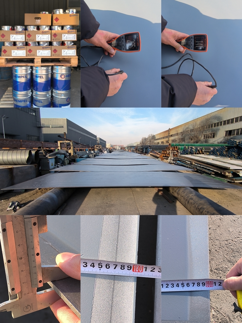
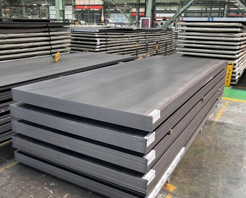
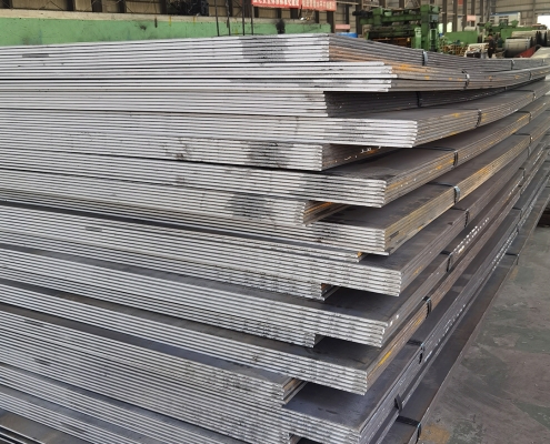
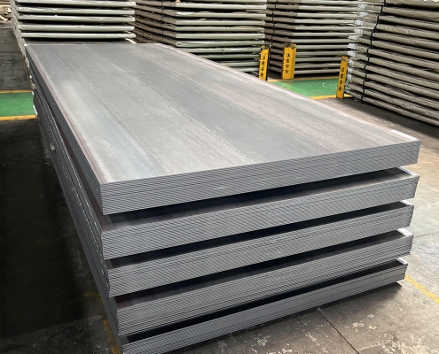
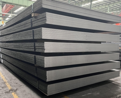
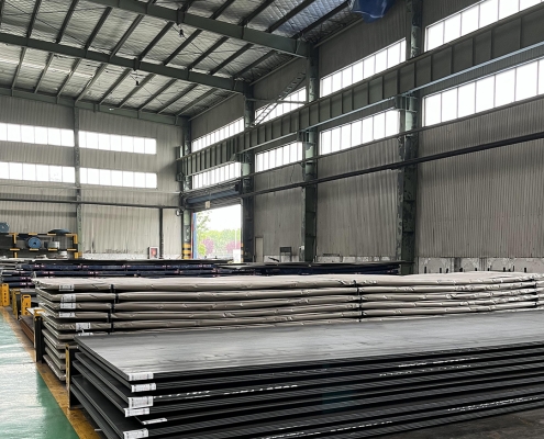
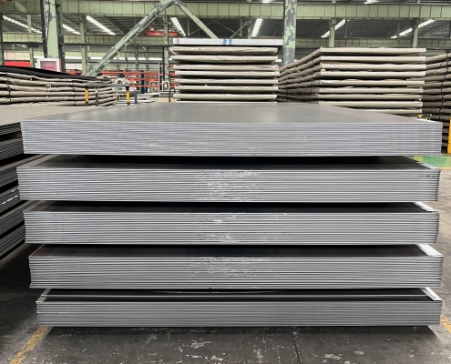
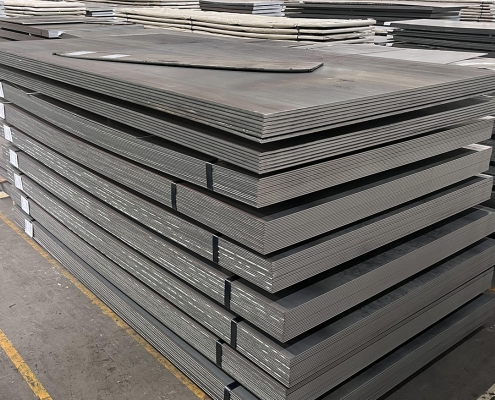
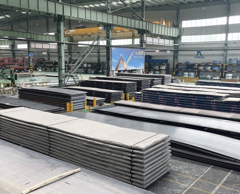
ZAM Coated Steel for Photovoltaic Brackets

Zinc-Aluminum-Magnesium (ZAM) vs Hot-dip galvanizing (HDG)

Tanım

What is Zinc-Aluminum-Magnesium (ZAM)?

Zinc-aluminum-magnesium (ZAM) is a high-performance metallic coating applied to steel designed to offer superior corrosion resistance, durability, and heat resistance compared to traditional galvanizing (zinc-only coatings). The coating combines zinc (Zn), aluminum (Al), and magnesium (Mg), which provides unique advantages in various applications.

ZAM Coating

ZAM Coating

What is Hot-dip galvanizing? (HDG)?

Hot-dip galvanization is a form of galvanization. It is the process of coating iron and steel with zinc, which alloys with the base metal surface when immersing the metal in a bath of molten zinc at a temperature of around 450 °C (842 °F). When exposed to the atmosphere, the pure zinc (Zn) reacts with oxygen (O2) to form zinc oxide (ZnO), which further reacts with carbon dioxide (CO2) to form zinc carbonate (ZnCO3), a usually dull grey, fairly strong material that protects the steel underneath from further corrosion in many circumstances.

Hot-dip Galvanizing

Hot-dip Galvanizing

Main Differences: Zinc-Aluminum-Magnesium (ZAM) vs Hot-dip galvanizing (HDG)

The comparison between zinc-aluminum-magnesium (ZAM) Ve hot-dip galvanizing (HDG) revolves around their coating composition, corrosion resistance, applications, cost, Ve environmental impact. Below is a detailed comparison to help understand their differences:

1. Coating Composition

Zinc-Aluminum-Magnesium (ZAM):
ZAM coatings are made of a combination of zinc (Zn), aluminum (Al), Ve magnesium (Mg). Typically, the composition is about 80-90% Zinc, 5-11% Aluminum, Ve 1-3% Magnesium. Including aluminum and magnesium gives the coating superior properties compared to zinc alone.

Hot-Dip Galvanizing (HDG):
HDG involves immersing steel into a molten bath of zinc (Zn) to form a protective zinc coating. The coating consists almost entirely of zinc, with small amounts of iron from the substrate, forming a zinc-iron alloy layer.

2. Korozyon Direnci

Zinc-Aluminum-Magnesium (ZAM):
Superior corrosion resistance compared to hot-dip galvanized steel. Adding aluminum increases the coating’s resistance to high temperatures and oxidation, while magnesium improves its resistance to corrosion in harsh environments like coastal, industrial, and chemical settings. ZAM has self-healing properties—if the coating is damaged, the magnesium component reacts with moisture to help prevent further corrosion.

Hot-Dip Galvanizing (HDG):
It provides good corrosion resistance but not as high as ZAM, especially in aggressive environments. The zinc coating is sacrificial, meaning it corrodes first to protect the underlying steel, but its effectiveness can be limited in humid, salty, veya chemical environments. HDG does not have the advanced self-healing properties that ZAM offers.

3. Durability and Longevity

Zinc-Aluminum-Magnesium (ZAM):
ZAM-coated products can last 2 to 4 times longer than traditional galvanized steel in harsh environments (e.g., coastal areas, chemical plants, etc.). The coating’s enhanced resistance to environmental factors contributes to a longer service life.

Hot-Dip Galvanizing (HDG):
The lifespan of HDG products is good but generally shorter than ZAM, particularly in extreme conditions. HDG can last for many years in less corrosive environments (e.g., mild climates), but its protection may degrade faster in severe environments.

4. Applications

Zinc-Aluminum-Magnesium (ZAM):
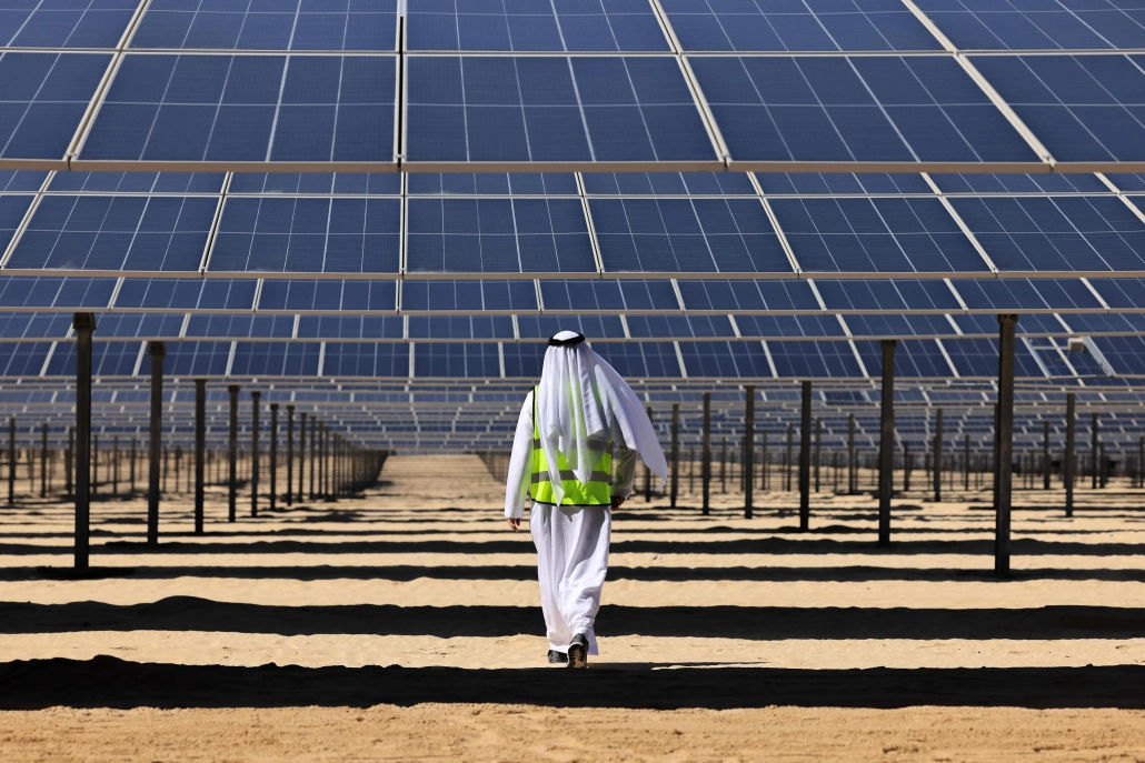
Ideal for zorlu ortamlar such as Coastal areas (where saltwater exposure is high), Chemical and industrial environments (where exposure to aggressive substances is every day), Solar panel mounts (due to its superior durability), Heavy-duty industrial applications (e.g., agricultural and mining equipment, steel structures exposed to extreme weather conditions).

Hot-Dip Galvanizing (HDG):
It is commonly used in general construction, automotive industries, outdoor infrastructure, Ve agricultural applications. It is suitable for general-purpose corrosion protection in outdoor conditions but not recommended for extreme or coastal environments.

5. Cost

Zinc-Aluminum-Magnesium (ZAM):
It is more expensive than traditional hot-dip galvanizing due to the inclusion of aluminum and magnesium and the more advanced coating process. The longer lifespan and lower maintenance costs in harsh environments often justify the higher initial cost.

Hot-Dip Galvanizing (HDG):
It is cheaper than ZAM, making it more suitable for projects where cost-efficiency is a priority and the environment is less aggressive. The relatively lower cost makes it ideal for large-scale production.

6. Environmental Impact

Zinc-Aluminum-Magnesium (ZAM):
The production of ZAM coatings is more environmentally friendly than hot-dip galvanizing, as it involves lower emissions of harmful gases and waste materials. The production process for ZAM generally generates less waste Ve fewer harmful emissions compared to traditional galvanizing methods.

Hot-Dip Galvanizing (HDG):
It is more environmentally intensive than ZAM, producing more waste gases and wastewater. However, modern improvements in the HDG process have aimed to reduce the environmental footprint, though it remains higher than ZAM.

7. Aesthetic Appearance

Zinc-Aluminum-Magnesium (ZAM):
ZAM has a matte gray finish with a smoother, more uniform appearance. This appearance can be more desirable in specific applications like architectural structures or solar panel mounts.

Hot-Dip Galvanizing (HDG):
HDG often has a shiny or dull metallic finish, depending on the thickness of the coating. While durable, its aesthetic appearance may be less appealing than ZAM’s, especially if the finish is uneven.

8. Ease of Processing and Welding

Zinc-Aluminum-Magnesium (ZAM):
ZAM coatings can be more challenging to process, weld, Ve paint than traditional galvanized steel, creating issues in some applications.

Hot-Dip Galvanizing (HDG):
HDG products are easier to weld and process than ZAM. However, the zinc coating can make welding and cutting more difficult due to zinc fumes, and special precautions may be required.

Summary Comparison Table: Zinc-Aluminum-Magnesium (ZAM) vs Hot-dip Galvanizing (HDG)

Özellik Zinc-Aluminum-Magnesium (ZAM) Hot-Dip Galvanizing (HDG)
Coating Composition Zinc, Aluminum, Magnesium Zinc (with some iron from the substrate)
Korozyon Direnci Superior, especially in harsh environments Good, but less effective in aggressive settings
Durability and Longevity 2-4 times longer than HDG in extreme environments Moderate lifespan, shorter in harsh conditions
Uygulamalar Coastal areas, chemical environments, heavy-duty General outdoor infrastructure, agriculture
Maliyet Higher initial cost Lower initial cost
Çevresel Etki Lower emissions and waste Higher emissions and waste
Aesthetic Appearance Matte gray, smoother finish Shiny or dull metallic finish
Ease of Processing It can be more challenging, especially with welding It is more straightforward to process and weld

Çözüm

ZAM is the best choice for extreme environments where superior corrosion resistance and durability are needed. Its long-term performance can justify the higher upfront cost.

HDG remains the go-to solution for general corrosion protection in less aggressive environments, providing a cost-effective and widely available option for most standard applications.

Pipeline vs Piping

Onshore vs Offshore Pipeline and Piping

giriiş

In the realm of energy transportation, the distinction between onshore and offshore pipelines and piping systems plays a crucial role in the efficiency, safety, and environmental impact of resource extraction and distribution. Onshore pipelines, typically situated on land, are designed to transport oil, gas, and other fluids over varying distances, benefiting from relatively more straightforward access for maintenance and monitoring. Conversely, offshore pipelines, laid on the seabed or suspended in water, present unique engineering challenges due to harsh marine conditions and logistical complexities. Understanding the Onshore vs Offshore Pipeline and Piping in design, construction, and operational considerations between these two types of pipelines is essential for optimizing infrastructure development and ensuring sustainable practices in the energy sector.

Definition: Onshore vs Offshore Pipeline and Piping

What is Pipeline?

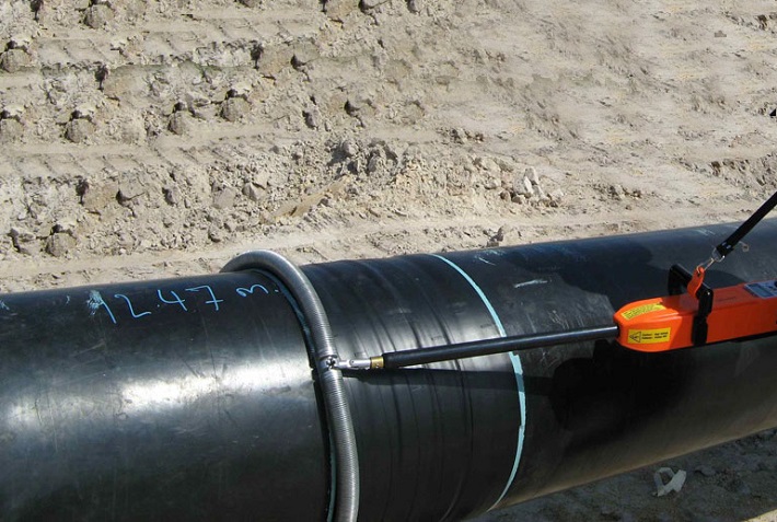
Pipeline is a long series of pipes, usually of large diameter, running underground, aboveground and underwater, such as a submarine pipeline, and equipped with fittings, such as valves and pumps, to control the flow of large quantities of fluid over long distances. Pipelines have large diameters, making it easy to transport liquids or gases in bulk from one place to another, sometimes for thousands of miles.

Pipeline

Pipeline

What is Piping?

Borulama is a system of pipes used to convey fluids (liquids and gases) from one location to another within the designated boundaries or spaces of petrochemical plants, power plants, refineries, etc. It is also equipped with valves and fittings to control the flow of fluids from one facility to another as needed, but only within the plant’s designated boundaries. Never skip these essential topics when taking an online course on piping engineering. Piping diameters range from 1/2 inch to 80 inches, depending on the facility’s design requirements for fluid transportation, usually from one facility to another within the facility’s boundaries.

Borulama

Borulama

What is Onshore Pipeline?

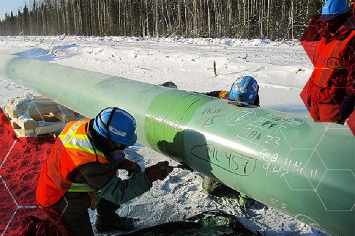
Onshore pipelines refer to networks of pipelines and related equipment used to transport fluids such as oil, natural gas, water, and chemicals in a land environment. These pipelines are integral to long-distance oil and gas transportation from oil fields to refineries, from natural gas wells to gas stations, and from crude oil and refined oil tank farms, chemical tank farms, LNG tank farms, and aircraft refueling pipeline operations.

Onshore Pipeline

Onshore Pipeline

What is Offshore Pipeline?

Offshore pipelines refer to the network of pipes and related equipment used to transport fluids such as oil, gas, water, and chemicals in an offshore environment. These pipelines are integral to operating offshore oil rigs, platforms and floating production storage and offloading units (FPSOs). The unique conditions of the offshore environment, such as high salinity, extreme temperatures, and strong currents, present significant challenges to the design and maintenance of these systems.

Offshore Pipeline

Offshore Pipeline

Main Differences: Onshore vs Offshore Pipeline and Piping

Comparison Table: Onshore vs Offshore Pipeline and Piping

Şartname Karada açık deniz
Pipeline Borulama Pipeline Borulama
Tasarım Kodları – ASME B31.4: Pipeline Transportation Systems for Liquids and Slurries
– ASME B31.8: Gas Transmission and Distribution Piping Systems
ASME B31.3: Process Piping – DNVGL-ST-F101: Submarine pipeline systems
– API RP 1111: Design, Construction, Operation, and Maintenance of Offshore Hydrocarbon Pipelines (Limit state design)
ASME B31.3: Process Piping
Kapsam Outside plant boundary
(Villages, fields, rivers, canals, railways, highways, cities, deserts, forests, hills, etc.)
Within plant boundary Outside plant boundary Within plant boundary
Type of pipe API Spec 5L: Specification for Line pipes – ASTM
– BS
– API 5L
API Spec 5L: Specification for Line pipes
– DNVGL-ST-F101: Submarine Pipeline Systems
ASTM Standartları
Vanalar – API 6D: Specification for Pipeline and Piping Valves
– Full Bore (FB) Ball Valves are used for pigs.
– BS
– API Standard
– Full bore (FB) and Reduced bore (RB)
– Full bore Valves: for smooth passage of intelligent pigs
– API 6D SS: Specification on Subsea Pipeline Valves
– RB valves
– BS/API standards
Kaynak – API Std. 1104: Welding of Pipelines and Related Facilities
– Type of welding: Automatic / Semi-Automatic/ Manual
– ASME Sec. IX: Standard for Welding and Brazing Procedures, Welders, Brazers and Welding and Brazing Operators
– Type of welding: Manual (mostly)
– API Std. 1104: Welding of Pipelines and Related Facilities
– Mostly automatic welding on pipelay barge.
– ASME Sec. IX: Standard for Welding and Brazing Procedures, Welders, Brazers and Welding and Brazing Operators
– Manual welding at the fabrication yard.
Weld joint inspection (NDT requirements) 100% by Automatic UT or RT (by using X-Ray) 5% to 100%
(mostly by using gamma rays)
100% by Automatic UT From 10% to 100% as required
Analyses – Wall Thickness Analysis
– Elastic Bend Radius Analysis
– Stability Analysis for Water Bodies/ Marshy Areas
– Horizontal directional drilling design analysis
– Railroad/ Highway Crossing Analysis
– Casing Pipe Analysis for Crossings
– Seismic Analysis
– Piping wall thickness calculation
– Piping Stress Analysis
Static Analysis
Dynamic Analysis
Wind Analysis
Flange Leakage Analysis
Seismic Analysis
– Wall thickness Analysis
– On-bottom Stability
– Span Analysis
– Global Buckling – Lateral and Upheaval
– Pipeline Expansion Analysis
– Riser Design (Span, Stress & Flexibility Analysis)
– Riser Clamp Design
– Pipeline Crossing Design and Analysis
– Deck piping stress analysis
Kurulum Buried (mostly) Above ground/On rack/slippers/T-postal etc. Subsea (in water on the seabed or buried in the seabed) Deck Platform Piping
(similar to plant)
Special Installations – Across rivers
– Horizontal Directional Drilling (HDD) method
– Micro-tunnelling method
– Across road/ rail/ highway
– Auger boring/ jacking boring method
– Shallow HDD
– Ghats/ Hills
– Modular installations
– Finning
– Studding
– Jacketing
– Spooling inside warehouse
– U/G piping for cooling water
– S-lay Method (for shallow water installation)
– J-Lay Method (for deep water installation)
– Shore pull/ barge pull near Land Fall Point (LFP)
Along with the deck structure
Special Equipment – Sectionalizing Valves (Remote operated)
– Insulating Joints
– Scraper Launcher/ Receiver
– Stem Extended Valves (for buried valves)
– Flow Tee
– Long Radius bends (R=6D)
– Cold field bends (R = 30D or 40D)
– Expansion Joints
– Motor Operator Valves (MOV)
– Cryogenic Valves
– Springs
– Subsea Isolation Valve (SSIV)
– LR Bends
– Flow tee
– Pipeline End Manifold (PLEM)
– Single Point Mooring (SPM) system
– Submarine hoses
– Floating hoses
– Cables and umbilical installation
– Piggy-back pipelines
Uygulanamaz
Survey – Topographical Survey
(all along the pipeline route)
– Geotechnical investigation
(all along the pipeline route)
– Soil resistivity survey
(all along the pipeline route)
– Hydrological Survey for water bodies (for scour depth calculation)
– Cadastral Survey (for RoU acquisition)
– Wind profile from meteorology
– Seismic study of plot
– Geophysical survey/ Bathymetric Survey by using side scan sonar, sub-bottom profiler, and echo-sounder
– Met-Ocean data collection
– Geotechnical data of the pipeline route
Uygulanamaz
Corrosion Protection Coating Three Layer Polyethylene (3LPE) coating
Three Layer Polypropylene (3LPP) coating
Fusion bonded epoxy (FBE) coating
– Coal tar enamel (CTE) Coating
Painting Coatings such as:
– Coal Tar Enamel Coating (CTE)
Three-layer polyethylene coating (3LPE)
Three-layer polypropylene coating (3LPP)
– Double-layer fusion bonded epoxy coating (2FBE)
Painting
Cathodic Protection System – Impressed Current Cathodic Protection (ICCP) system
– Sacrificial Anode (limited locations)
Not applicable Sacrificial Anodic Cathodic Protection (SACP) system Uygulanamaz
Hydrostatic testing – Gauge Plate run of 95% of the ID of the highest pipe thickness
– Test Pressure
Minimum: 1.25 times of Design Pressure (for liquid pipelines)
1.25 to 1.5 times of Design Pressure (for gas pipelines)
Maximum: Pressure equivalent to Hoop stress of 95% of SMYS of pipe material
– Hold period: 24 hours
– No gauge plate run is done. Generally, cardboard blasting is done to clean the piping.
– Test Pressure
Minimum: 1.5 × Design Pressure × Temperature Factor
Maximum: Based on line schedule
– Hold period: 2 – 6 hours
– Gauge Plate run of 95% of the ID of the highest pipeline thickness.
– Test Pressure
Minimum: 1.25 times x Design Pressure
– Hold period: 24 hours
– No gauging is done.
– Test Pressure
Maximum: As per line schedule
– Hold period: 2 hours
Preservation – Preservation of pipeline with corrosion-inhibited water or by filling of inert gas (N2) Not applicable
Pigging Intelligent Pigging Not applicable Compliant Not applicable
Machines/Equipment required for installation – Trencher
– Backhoe/ Excavator
– Side Boom
– Cold field bending machine
– Holiday Detection Machines
– Pneumatic/ Hydraulic Internal Clamps
Crane/ Hydra – Pipelay Barge
– Derrick Barge
– Diving support vessel
– Dynamic Positioning (DP) barge (for deepwater)
Pre-fabricated deck piping

Conclusion: Onshore vs Offshore Pipeline and Piping

In summary, Onshore pipelines are usually buried or erected on land to transport oil, natural gas, drinking water, sewage, seawater, slurry, etc. Onshore piping is typically erected in petrochemical plants, power plants, refineries, fire protection systems, water treatment systems, etc., while Offshore pipelines are buried on the seabed. Offshore piping typically consists of transmission and structural support pipeline systems on offshore drilling platforms. Special offshore equipment includes underwater isolation valves, tees, and submarine hoses. Offshore surveys include geophysics, bathymetry, and ocean data collection, while onshore surveys focus on topographic and geotechnical engineering studies.

L80-9Cr vs L80-13Cr

L80-9Cr vs L80-13Cr: Something You Need to Know

Choosing the proper casing and tubing materials can ensure safety and efficiency in oil and gas drilling and exploration. L80-9Cr and L80-13Cr are two alloy steel grades commonly used in petroleum casing and tubing. Each grade has unique characteristics and applications. L80-9Cr vs L80-13Cr, this article will delve into the difference between these materials to help you make an informed decision.

1. Overview of L80 Grade

L80 is an alloy steel used in the oil and gas sector. It is known for its good strength and corrosion resistance. It is typically employed in high-temperature and high-pressure environments and is suitable for both oil and gas production.

1.1 L80-9Cr

Composition: Contains 9% chromium, enhancing the material’s oxidation resistance at high temperatures.
Özellikler:
Corrosion Resistance: It performs well in CO2 environments, making it suitable for acidic gas pipelines.
Mechanical Strength: Provides good strength and is suitable for high-temperature operations.
Applications: Commonly used in high-temperature gas pipelines in oil fields.

1.2 L80-13Cr

Composition: Contains 13% chromium, offering higher corrosion resistance.
Özellikler:
Corrosion Resistance: Exhibits superior performance in environments with H2S and CO2, suitable for extreme conditions.
Mechanical Strength: Offers higher strength and is ideal for complex operational environments.
Applications: Used in high-corrosion environments and deep well operations.

L80-9Cr vs L80-13Cr

L80-9Cr and L80-13Cr Casing and Tubing in Oil and Gas Drilling and Exploration

2. Comparison: L80-9Cr vs L80-13Cr

2.1 Chemical Composition

Standart Seviye C Si Mn P S CR Ay Ni Cu
API 5CT L80-9Cr ≤ 0,15 ≤ 1.00 0.30-0.60 ≤ 0,020 ≤ 0,010 8.00-10.00 0.90-1.10 ≤ 0.50 ≤ 0,25
L80-13Cr 0.15-0.22 ≤ 1.00 0.25-1.00 ≤ 0,020 ≤ 0,010 12.00-14.00 ≤ 0.50 ≤ 0,25

2.2 Mekanik Özellikler

Standart Seviye Yield Strength (Mpa) Çekme Dayanımı (Mpa) Uzama (%) Hardness max
dk. max. dk. dk. sıcak rulo HBW
API 5CT L80-9Cr 552 655 655 API 5CT
Table C.7
23 241
L80-13Cr 552 655 655 23 241

2.3 Impact Test

Standart Seviye Sharpy Impact Energy (J)
Coupling Boru Gövdesi
API 5CT L80-9Cr L-10-40-0 T-10-20-0 L-10-27-0 T-10-14-0
L80-13Cr L-10-40-0 T-10-20-0 L-10-27-0 T-10-14-0

2.4 Corrosion Resistance

L80-9Cr: The 9% chromium content provides moderate corrosion resistance, suitable for environments with low to moderate concentrations of H₂S (hydrogen sulfide) or CO₂ (carbon dioxide), typically seen in less aggressive environments.

L80-13Cr: The 13% chromium content provides enhanced resistance to sour service (i.e., environments with high levels of H₂S) and high CO₂ environments. It’s better for harsher conditions like deep wells or offshore drilling.

2.5 Temperature and Sour Service

L80-9Cr: Generally suitable for moderate-temperature environments.

L80-13Cr: Can withstand higher temperatures and is better equipped for sour service conditions with high concentrations of H₂S or CO₂.

2.6 Cost

L80-9Cr: Due to its lower chromium content, L80-9Cr is less expensive than L80-13Cr. If the environment is not highly corrosive or sour, L80-9Cr could be a more cost-effective option.

L80-13Cr: More expensive but provides superior resistance in harsh conditions, potentially reducing maintenance costs or failures over time.

2.7 Applications

L80-9Cr: Suitable in wells with moderate temperature, pressure, and sour gas conditions. Often used in conventional oil and gas wells or less aggressive service environments.

L80-13Cr: Ideal for high-pressure wells with harsh environmental conditions, particularly in sour gas service, deep wells, or offshore oil & gas operations where high corrosion resistance is critical.

Açık Deniz Rüzgar Türbinleri

Kara ve Deniz Rüzgar Türbinleri için Yapısal Dairesel İçi Boş Kesitler

Yenilenebilir enerjiye olan talep küresel olarak artmaya devam ederken, açık deniz rüzgar enerjisi hayati bir çözüm olarak ortaya çıkmıştır. Bu makale, açık deniz rüzgar türbinlerinin destekleyici yapılarında kullanılan yapısal dairesel içi boş kesitlerin (CHS) önemini ele alarak tasarımlarını, malzeme özelliklerini ve uygulamalarını incelemektedir.

1. Yapısal Dairesel Boş Kesitleri Anlamak

Yapısal dairesel içi boş kesitler içi boş bir merkeze sahip silindirik tüplerdir. Bu bölümler, öncelikle türbinin ağırlığını taşımak ve dış çevre basınçlarına dayanmak üzere tasarlanmış olan açık deniz rüzgar türbinlerinin destek yapılarında önemli bir rol oynar.

2. Yapısal Dairesel Boş Kesitlerin Malzeme Özellikleri

Karbon Çelik: S355MH, S355MLH, S420MH, S420MLH, S460MH, S460MLH, S460QH, S460QLH, S620QH, S620QLH, S690QH, S690QLH

3. Tasarım Hususları

Açık deniz rüzgar türbinleri için destekleyici yapılar tasarlanırken çeşitli faktörler göz önünde bulundurulmalıdır:
Rüzgar Yükü: Türbinler, çalışma sırasında rüzgardan kaynaklanan dinamik yüklere maruz kalırlar ve bu da yapısal kararlılığı sağlayan bir tasarımı gerekli kılar.
Dalga Etkisi: Deniz ortamlarındaki dalgalar yapılar üzerinde ek basınç oluşturur, bu da dikkatli hesaplama ve tasarım ayarlamaları gerektirir.
Korozyon Koruması: Deniz suyunun aşındırıcı özelliği göz önüne alındığında, yapının ömrünü uzatmak için koruyucu kaplamalar veya korozyona dayanıklı malzemeler kullanmak esastır.

4. Dairesel Boş Bölümlerin Kullanımının Avantajları

Destek yapılarında dairesel içi boş profillerin kullanılması çeşitli avantajlar sağlar:
Yüksek Basınç Dayanımı: Dairesel kesit, basıncın eşit dağılımını sağlayarak genel stabiliteyi artırır.
Hafif: Diğer şekillerle karşılaştırıldığında dairesel borular, daha az ağırlıkla benzer mukavemet sağlar, bu da nakliye ve montajı kolaylaştırır.
Yapım Kolaylığı: Dairesel boruların bağlanması ve kaynaklanmasının basit olması, yapı verimliliğini artırır.

5. Sıkça Sorulan Sorular

Q: Yapısal dairesel kesitli profillerde hangi malzeme seçilmelidir?
A: Malzeme seçimi belirli çevre koşullarına, bütçeye ve tasarım gereksinimlerine bağlıdır. Karbon çeliği çoğu uygulama için uygundur, ancak yüksek aşındırıcı ortamlarda paslanmaz çelik veya alaşımlı çelik daha uygun olabilir.

Q: Yapısal dairesel kesitli profillerin dayanıklılığı nasıl sağlanır?
A: Dayanıklılığı sağlamak için düzenli denetimler ve bakım hayati önem taşır. Ayrıca, uygun koruyucu kaplamalar ve malzemeler seçmek yapıların ömrünü önemli ölçüde uzatabilir.

6. Sonuç

Yapısal dairesel içi boş kesitler, açık deniz rüzgar türbinlerinin destekleyici yapılarında vazgeçilmezdir. Dikkatli tasarım ve malzeme seçimiyle rüzgar türbinleri, kararlılık ve dayanıklılık açısından geliştirilebilir ve böylece yenilenebilir enerji gelişimi ilerletilebilir.

Kara ve deniz rüzgar türbini yapıları için yapısal içi boş profiller hakkında daha fazla bilgi veya yardım için lütfen şu adrese ulaşmaktan çekinmeyin: [email protected].

Ham Çelik Üretimi

Eylül 2024'te Ham Çelik Üretimi

Eylül 2024'te Dünya Çelik Birliği'ne (world steel) rapor veren 71 ülkenin dünya ham çelik üretimi 143,6 milyon ton (Mt) olarak gerçekleşti ve Eylül 2023'e göre 4,7% düşüş yaşandı.

ham çelik üretimi

ham çelik üretimi

Bölgelere göre ham çelik üretimi

Afrika, Eylül 2024'te 1,9 Mt üretti ve Eylül 2023'e göre 2,61 TP3 T arttı. Asya ve Okyanusya 105,3 Mt üretti ve 5,01 TP3 T azaldı. AB (27) 10,5 Mt üretti ve 0,31 TP3 T arttı. Avrupa, Diğer 3,6 Mt üretti ve 4,11 TP3 T arttı. Orta Doğu 3,5 Mt üretti ve 23,01 TP3 T azaldı. Kuzey Amerika 8,6 Mt üretti ve 3,41 TP3 T azaldı. Rusya ve diğer BDT + Ukrayna 6,8 Mt üretti ve 7,61 TP3 T azaldı. Güney Amerika 3,5 Mt üretti ve 3,31 TP3 T arttı.

Tablo 1. Bölgelere göre ham çelik üretimi

Bölge Eylül 2024 (Mt) % değişikliği 24/23 Eylül Ocak-Eylül 2024 (Mt) % Ocak-Eylül 24/23'te değişti
Afrika 1.9 2.6 16.6 2.3
Asya ve Okyanusya 105.3 -5 1,032.00 -2.5
AB (27) 10.5 0.3 97.8 1.5
Avrupa, Diğer 3.6 4.1 33.1 7.8
Orta Doğu 3.5 -23 38.4 -1.5
Kuzey Amerika 8.6 -3.4 80 -3.9
Rusya ve diğer BDT ülkeleri + Ukrayna 6.8 -7.6 64.9 -2.5
Güney Amerika 3.5 3.3 31.4 0
Toplam 71 ülke 143.6 -4.7 1,394.10 -1.9

Bu tabloda yer alan 71 ülke, 2023 yılında toplam dünya ham çelik üretiminin yaklaşık 98%'sini oluşturmuştur.

Tabloda yer alan bölgeler ve ülkeler:

  • Afrika: Cezayir, Mısır, Libya, Fas, Güney Afrika, Tunus
  • Asya ve Okyanusya: Avustralya, Çin, Hindistan, Japonya, Moğolistan, Yeni Zelanda, Pakistan, Güney Kore, Tayvan (Çin), Tayland, Vietnam
  • Avrupa Birliği (27): Avusturya, Belçika, Bulgaristan, Hırvatistan, Çekya, Finlandiya, Fransa, Almanya, Yunanistan, Macaristan, İtalya, Lüksemburg, Hollanda, Polonya, Portekiz, Romanya, Slovakya, Slovenya, İspanya, İsveç
  • Avrupa, Diğer: Makedonya, Norveç, Sırbistan, Türkiye, Birleşik Krallık
  • Orta Doğu: Bahreyn, İran, Irak, Ürdün, Kuveyt, Umman, Katar, Suudi Arabistan, Birleşik Arap Emirlikleri, Yemen
  • Kuzey Amerika: Kanada, Küba, El Salvador, Guatemala, Meksika, Amerika Birleşik Devletleri
  • Rusya ve diğer BDT ülkeleri + Ukrayna: Beyaz Rusya, Kazakistan, Rusya, Ukrayna
  • Güney Amerika: Arjantin, Brezilya, Şili, Kolombiya, Ekvador, Paraguay, Peru, Uruguay, Venezuela

En çok çelik üreten 10 ülke

Çin, Eylül 2024'te 77,1 Mt üretti ve Eylül 2023'e göre 6,11 TP3T düşüş yaşadı. Hindistan, 0,21 TP3T düşüşle 11,7 Mt üretti. Japonya, 5,81 TP3T düşüşle 6,6 Mt üretti. Amerika Birleşik Devletleri, 1,21 TP3T artışla 6,7 Mt üretti. Rusya'nın, 10,31 TP3T düşüşle 5,6 Mt ürettiği tahmin ediliyor. Güney Kore, 1,31 TP3T artışla 5,5 Mt üretti. Almanya, 4,31 TP3T artışla 3,0 Mt üretti. Türkiye, 6,51 TP3T artışla 3,1 Mt üretti. Brezilya, 9,91 TP3T artışla 2,8 Mt üretti. İran'ın, 41,21 TP3T düşüşle 1,5 Mt ürettiği tahmin ediliyor.

Tablo 2. En çok çelik üreten 10 ülke

Bölge  Eylül 2024 (Mt) % değişikliği 24/23 Eylül Ocak-Eylül 2024 (Mt) % Ocak-Eylül 24/23'te değişti
Çin 77.1 -6.1 768.5 -3.6
Hindistan 11.7 -0.2 110.3 5.8
Japonya 6.6 -5.8 63.3 -3.2
Amerika Birleşik Devletleri 6.7 1.2 60.3 -1.6
Rusya 5.6 e -10.3 54 -5.5
Güney Kore 5.5 1.3 48.1 -4.6
Almanya 3 4.3 28.4 4
Türkiye 3.1 6.5 27.9 13.8
Brezilya 2.8 9.9 25.2 4.4
İran 1.5 e -41.2 21.3 -3.1

e – tahmini. En iyi 10 üretici ülkenin sıralaması, yılın başından bu yana toplam üretime dayanmaktadır.

API 5L ve ISO 3183

Farkları Öğrenin: API 5L ve ISO 3183

ISO 3183 ve API 5L, çelik borularla ilgili standartlardır ve öncelikli olarak petrol, gaz ve diğer sıvı taşıma endüstrilerinde kullanılır. Bu iki standart arasında önemli bir örtüşme olsa da, API 5L ve ISO 3183 arasında kapsam, uygulama ve bunların ardındaki organizasyonlarda önemli farklılıklar vardır.

1. Sertifika Veren Kuruluşlar: API 5L ve ISO 3183

API 5L: Amerikan Petrol Enstitüsü (API) tarafından yayınlanan bu standart, öncelikle petrol ve gaz endüstrisinde kullanılır. Petrol, gaz ve su taşıyan çelik borular için teknik gereklilikleri ayrıntılı olarak açıklar.
ISO 3183: Uluslararası Standardizasyon Örgütü (ISO) tarafından yayınlanan bu standart, uluslararası alanda tanınmaktadır ve petrol ve gaz taşımacılığı sektöründe çelik borular için küresel olarak kullanılmaktadır.

2. Uygulama Kapsamı: API 5L ve ISO 3183

API 5L: Petrol, doğal gaz ve diğer sıvıların yüksek basınç altında taşınması için çelik boruları kapsar. Kuzey Amerika'da, özellikle Amerika Birleşik Devletleri'nde yaygın olarak kullanılır.
ISO 3183: Bu standart, öncelikle petrol ve doğalgaz boru hatlarında kullanılan çelik boruların tasarımı, imalatı ve kalite kontrolüne odaklanmaktadır, ancak kullanımı daha uluslararası olup dünya çapında çeşitli ülkelerde uygulanabilir.

3. Temel Farklar: API 5L ve ISO 3183

Coğrafi ve Pazar Odaklılık:

API 5L, Kuzey Amerika pazarına (özellikle ABD) daha uygunken, ISO 3183 uluslararası alanda uygulanabilir olup dünya çapında birçok ülkede kullanılmaktadır.

Çelik Sınıfları ve Gereksinimleri:

API 5L, L175, L210, L245 gibi çelik sınıflarını tanımlar; buradaki sayı, megapaskal (MPa) cinsinden minimum akma dayanımını temsil eder.
ISO 3183 de benzer sınıfları tanımlar ancak uluslararası endüstri uygulamalarıyla uyumlu olarak malzeme özellikleri, üretim süreçleri ve muayene protokolleri ile ilgili daha ayrıntılı gereklilikler içerir.
Ek Özellikler:
API 5L, kalite kontrolü, sertifikasyon ve üretim gerekliliklerini vurgularken, ISO 3183 uluslararası ticareti göz önünde bulundurarak daha geniş bir kapsamı kapsar ve sıcaklık, çevre ve belirli mekanik gereklilikler de dahil olmak üzere farklı koşullar için özellikler sağlar.

4. Teknik Gereksinimler: API 5L ve ISO 3183

API 5L, çelik boruların malzeme özelliklerini, üretim süreçlerini, boyutlarını, test yöntemlerini ve kalite kontrolünü belirtir. Çelik sınıflarını L'den (düşük mukavemet) X sınıflarına (yüksek mukavemet) kadar, örneğin X42, X60 ve X70 olarak tanımlar.
ISO 3183, malzeme kalitesi, ısıl işlem, yüzey işlemi ve boru uçları dahil olmak üzere çelik boru üretiminin benzer yönlerini kapsar. Ayrıca boru hattı tasarım basıncı, çevresel hususlar ve çeşitli boru hattı aksesuarları için ayrıntılı özellikler sağlar.

5. Boru Sınıflarının Karşılaştırılması: API 5L ve ISO 3183

API 5L: Sınıflar L sınıflarından (düşük akma dayanımı) X sınıflarına (daha yüksek akma dayanımı) kadar değişir. Örneğin, X60, 60.000 psi (yaklaşık 413 MPa) akma dayanımına sahip boruları ifade eder.
ISO 3183: Benzer bir derecelendirme sistemi kullanır ancak daha ayrıntılı sınıflandırmalar ve koşullar içerebilir. Ayrıca küresel boru hattı tasarımı ve operasyonel uygulamalarla uyumu sağlar.

6. Standartlar Arası Uyumluluk:

Birçok durumda API 5L ve ISO 3183 uyumludur, yani API 5L gerekliliklerini karşılayan bir çelik boru genellikle ISO 3183 gerekliliklerini de karşılayacaktır ve bunun tersi de geçerlidir. Ancak, belirli boru hattı projeleri konuma, müşteri tercihlerine veya düzenleyici gerekliliklere bağlı olarak bir standarda diğerine göre uyabilir.

7. Sonuç:

API 5L, Amerika Birleşik Devletleri ve çevre bölgelerde daha yaygındır. Petrol ve gaz boru hattı endüstrisine odaklanır ve üretim ve kalite kontrolüne güçlü bir şekilde vurgu yapar.
ISO 3183, küresel petrol ve gaz boru hattı projeleri için uluslararası bir standarttır. Daha ayrıntılı, küresel olarak uyumlu gereksinimleri, uluslararası pazarlarda daha geniş kabul görmesini sağlar.

Her iki standart da malzeme, üretim ve test özellikleri açısından oldukça benzerdir. Yine de, ISO 3183 daha geniş, daha küresel olarak uygulanabilir bir kapsama sahip olma eğilimindeyken, API 5L Kuzey Amerika pazarına daha özgüdür. Bu standartlar arasındaki seçim, boru hattı projesinin coğrafi konumuna, özelliklerine ve düzenleyici ihtiyaçlarına bağlıdır.