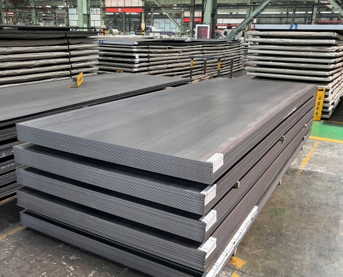
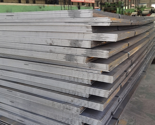
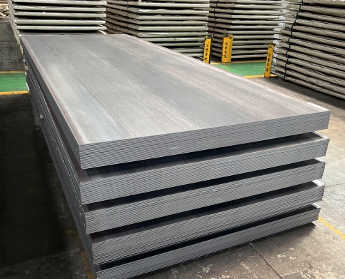
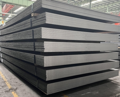
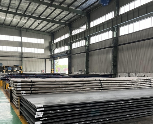
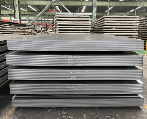
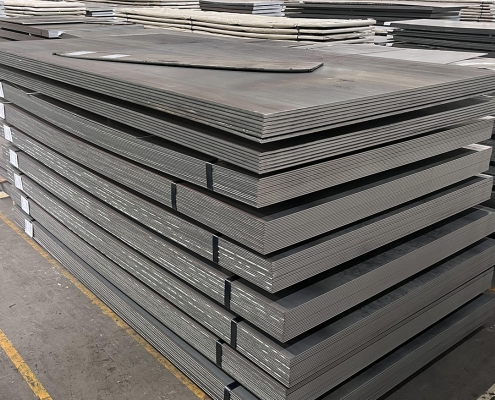
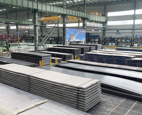
ZAM Coated Steel for Photovoltaic Brackets

Zinc-Aluminum-Magnesium (ZAM) vs Hot-dip galvanizing (HDG)

Определение

What is Zinc-Aluminum-Magnesium (ZAM)?

Zinc-aluminum-magnesium (ZAM) is a high-performance metallic coating applied to steel designed to offer superior corrosion resistance, durability, and heat resistance compared to traditional galvanizing (zinc-only coatings). The coating combines zinc (Zn), aluminum (Al), and magnesium (Mg), which provides unique advantages in various applications.

ZAM Coating

ZAM Coating

What is Hot-dip galvanizing? (HDG)?

Hot-dip galvanization is a form of galvanization. It is the process of coating iron and steel with zinc, which alloys with the base metal surface when immersing the metal in a bath of molten zinc at a temperature of around 450 °C (842 °F). When exposed to the atmosphere, the pure zinc (Zn) reacts with oxygen (O2) to form zinc oxide (ZnO), which further reacts with carbon dioxide (CO2) to form zinc carbonate (ZnCO3), a usually dull grey, fairly strong material that protects the steel underneath from further corrosion in many circumstances.

Hot-dip Galvanizing

Hot-dip Galvanizing

Main Differences: Zinc-Aluminum-Magnesium (ZAM) vs Hot-dip galvanizing (HDG)

The comparison between zinc-aluminum-magnesium (ZAM) и hot-dip galvanizing (HDG) revolves around their coating composition, corrosion resistance, applications, cost, и environmental impact. Below is a detailed comparison to help understand their differences:

1. Coating Composition

Zinc-Aluminum-Magnesium (ZAM):
ZAM coatings are made of a combination of zinc (Zn), aluminum (Al), и magnesium (Mg). Typically, the composition is about 80-90% Zinc, 5-11% Aluminum, и 1-3% Magnesium. Including aluminum and magnesium gives the coating superior properties compared to zinc alone.

Hot-Dip Galvanizing (HDG):
HDG involves immersing steel into a molten bath of zinc (Zn) to form a protective zinc coating. The coating consists almost entirely of zinc, with small amounts of iron from the substrate, forming a zinc-iron alloy layer.

2. Коррозионная стойкость

Zinc-Aluminum-Magnesium (ZAM):
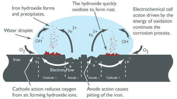
Superior corrosion resistance compared to hot-dip galvanized steel. Adding aluminum increases the coating’s resistance to high temperatures and oxidation, while magnesium improves its resistance to corrosion in harsh environments like coastal, industrial, and chemical settings. ZAM has self-healing properties—if the coating is damaged, the magnesium component reacts with moisture to help prevent further corrosion.

Hot-Dip Galvanizing (HDG):
It provides good corrosion resistance but not as high as ZAM, especially in aggressive environments. The zinc coating is sacrificial, meaning it corrodes first to protect the underlying steel, but its effectiveness can be limited in humid, salty, или chemical environments. HDG does not have the advanced self-healing properties that ZAM offers.

3. Durability and Longevity

Zinc-Aluminum-Magnesium (ZAM):
ZAM-coated products can last 2 to 4 times longer than traditional galvanized steel in harsh environments (e.g., coastal areas, chemical plants, etc.). The coating’s enhanced resistance to environmental factors contributes to a longer service life.

Hot-Dip Galvanizing (HDG):
The lifespan of HDG products is good but generally shorter than ZAM, particularly in extreme conditions. HDG can last for many years in less corrosive environments (e.g., mild climates), but its protection may degrade faster in severe environments.

4. Applications

Zinc-Aluminum-Magnesium (ZAM):
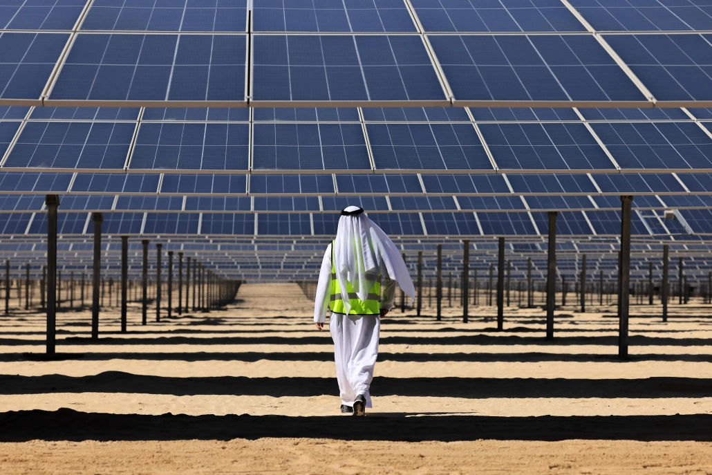
Ideal for суровые условия such as Coastal areas (where saltwater exposure is high), Chemical and industrial environments (where exposure to aggressive substances is every day), Solar panel mounts (due to its superior durability), Heavy-duty industrial applications (e.g., agricultural and mining equipment, steel structures exposed to extreme weather conditions).

Hot-Dip Galvanizing (HDG):
It is commonly used in general construction, automotive industries, outdoor infrastructure, и agricultural applications. It is suitable for general-purpose corrosion protection in outdoor conditions but not recommended for extreme or coastal environments.

5. Cost

Zinc-Aluminum-Magnesium (ZAM):
It is more expensive than traditional hot-dip galvanizing due to the inclusion of aluminum and magnesium and the more advanced coating process. The longer lifespan and lower maintenance costs in harsh environments often justify the higher initial cost.

Hot-Dip Galvanizing (HDG):
It is cheaper than ZAM, making it more suitable for projects where cost-efficiency is a priority and the environment is less aggressive. The relatively lower cost makes it ideal for large-scale production.

6. Environmental Impact

Zinc-Aluminum-Magnesium (ZAM):
The production of ZAM coatings is more environmentally friendly than hot-dip galvanizing, as it involves lower emissions of harmful gases and waste materials. The production process for ZAM generally generates less waste и fewer harmful emissions compared to traditional galvanizing methods.

Hot-Dip Galvanizing (HDG):
It is more environmentally intensive than ZAM, producing more waste gases and wastewater. However, modern improvements in the HDG process have aimed to reduce the environmental footprint, though it remains higher than ZAM.

7. Aesthetic Appearance

Zinc-Aluminum-Magnesium (ZAM):
ZAM has a matte gray finish with a smoother, more uniform appearance. This appearance can be more desirable in specific applications like architectural structures or solar panel mounts.

Hot-Dip Galvanizing (HDG):
HDG often has a shiny or dull metallic finish, depending on the thickness of the coating. While durable, its aesthetic appearance may be less appealing than ZAM’s, especially if the finish is uneven.

8. Ease of Processing and Welding

Zinc-Aluminum-Magnesium (ZAM):
ZAM coatings can be more challenging to process, weld, и paint than traditional galvanized steel, creating issues in some applications.

Hot-Dip Galvanizing (HDG):
HDG products are easier to weld and process than ZAM. However, the zinc coating can make welding and cutting more difficult due to zinc fumes, and special precautions may be required.

Summary Comparison Table: Zinc-Aluminum-Magnesium (ZAM) vs Hot-dip Galvanizing (HDG)

Особенность Zinc-Aluminum-Magnesium (ZAM) Hot-Dip Galvanizing (HDG)
Coating Composition Zinc, Aluminum, Magnesium Zinc (with some iron from the substrate)
Устойчивость к коррозии Superior, especially in harsh environments Good, but less effective in aggressive settings
Durability and Longevity 2-4 times longer than HDG in extreme environments Moderate lifespan, shorter in harsh conditions
Приложения Coastal areas, chemical environments, heavy-duty General outdoor infrastructure, agriculture
Расходы Higher initial cost Lower initial cost
Воздействие на окружающую среду Lower emissions and waste Higher emissions and waste
Aesthetic Appearance Matte gray, smoother finish Shiny or dull metallic finish
Ease of Processing It can be more challenging, especially with welding It is more straightforward to process and weld

Заключение

ZAM is the best choice for extreme environments where superior corrosion resistance and durability are needed. Its long-term performance can justify the higher upfront cost.

HDG remains the go-to solution for general corrosion protection in less aggressive environments, providing a cost-effective and widely available option for most standard applications.

Pipeline vs Piping

Onshore vs Offshore Pipeline and Piping

Введение

In the realm of energy transportation, the distinction between onshore and offshore pipelines and piping systems plays a crucial role in the efficiency, safety, and environmental impact of resource extraction and distribution. Onshore pipelines, typically situated on land, are designed to transport oil, gas, and other fluids over varying distances, benefiting from relatively more straightforward access for maintenance and monitoring. Conversely, offshore pipelines, laid on the seabed or suspended in water, present unique engineering challenges due to harsh marine conditions and logistical complexities. Understanding the Onshore vs Offshore Pipeline and Piping in design, construction, and operational considerations between these two types of pipelines is essential for optimizing infrastructure development and ensuring sustainable practices in the energy sector.

Definition: Onshore vs Offshore Pipeline and Piping

What is Pipeline?

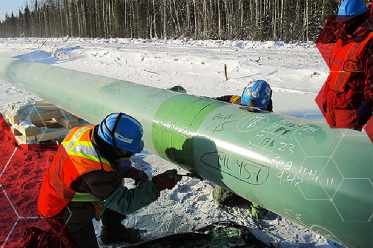
Pipeline is a long series of pipes, usually of large diameter, running underground, aboveground and underwater, such as a submarine pipeline, and equipped with fittings, such as valves and pumps, to control the flow of large quantities of fluid over long distances. Pipelines have large diameters, making it easy to transport liquids or gases in bulk from one place to another, sometimes for thousands of miles.

Pipeline

Pipeline

What is Piping?

Трубопровод is a system of pipes used to convey fluids (liquids and gases) from one location to another within the designated boundaries or spaces of petrochemical plants, power plants, refineries, etc. It is also equipped with valves and fittings to control the flow of fluids from one facility to another as needed, but only within the plant’s designated boundaries. Never skip these essential topics when taking an online course on piping engineering. Piping diameters range from 1/2 inch to 80 inches, depending on the facility’s design requirements for fluid transportation, usually from one facility to another within the facility’s boundaries.

Трубопровод

Трубопровод

What is Onshore Pipeline?

Onshore pipelines refer to networks of pipelines and related equipment used to transport fluids such as oil, natural gas, water, and chemicals in a land environment. These pipelines are integral to long-distance oil and gas transportation from oil fields to refineries, from natural gas wells to gas stations, and from crude oil and refined oil tank farms, chemical tank farms, LNG tank farms, and aircraft refueling pipeline operations.

Onshore Pipeline

Onshore Pipeline

What is Offshore Pipeline?

Offshore pipelines refer to the network of pipes and related equipment used to transport fluids such as oil, gas, water, and chemicals in an offshore environment. These pipelines are integral to operating offshore oil rigs, platforms and floating production storage and offloading units (FPSOs). The unique conditions of the offshore environment, such as high salinity, extreme temperatures, and strong currents, present significant challenges to the design and maintenance of these systems.

Offshore Pipeline

Offshore Pipeline

Main Differences: Onshore vs Offshore Pipeline and Piping

Comparison Table: Onshore vs Offshore Pipeline and Piping

Спецификация Береговой Оффшор
Pipeline Трубопровод Pipeline Трубопровод
Коды дизайна – ASME B31.4: Pipeline Transportation Systems for Liquids and Slurries
– ASME B31.8: Gas Transmission and Distribution Piping Systems
ASME B31.3: Process Piping – DNVGL-ST-F101: Submarine pipeline systems
– API RP 1111: Design, Construction, Operation, and Maintenance of Offshore Hydrocarbon Pipelines (Limit state design)
ASME B31.3: Process Piping
Объем Outside plant boundary
(Villages, fields, rivers, canals, railways, highways, cities, deserts, forests, hills, etc.)
Within plant boundary Outside plant boundary Within plant boundary
Type of pipe API Spec 5L: Specification for Line pipes – ASTM
– BS
– API 5L
API Spec 5L: Specification for Line pipes
– DNVGл-ST-F101: Submarine Pipeline Systems
Стандарты АСТМ
Клапаны – API 6D: Specification for Pipeline and Piping Valves
– Full Bore (FB) Ball Valves are used for pigs.
– BS
– API Standard
– Full bore (FB) and Reduced bore (RB)
– Full bore Valves: for smooth passage of intelligent pigs
– API 6D SS: Specification on Subsea Pipeline Valves
– RB valves
– BS/API standards
Сварка – API Std. 1104: Welding of Pipelines and Related Facilities
– Type of welding: Automatic / Semi-Automatic/ Manual
– ASME Sec. IX: Standard for Welding and Brazing Procedures, Welders, Brazers and Welding and Brazing Operators
– Type of welding: Manual (mostly)
– API Std. 1104: Welding of Pipelines and Related Facilities
– Mostly automatic welding on pipelay barge.
– ASME Sec. IX: Standard for Welding and Brazing Procedures, Welders, Brazers and Welding and Brazing Operators
– Manual welding at the fabrication yard.
Weld joint inspection (NDT requirements) 100% by Automatic UT or RT (by using X-Ray) 5% to 100%
(mostly by using gamma rays)
100% by Automatic UT From 10% to 100% as required
Analyses – Wall Thickness Analysis
– Elastic Bend Radius Analysis
– Stability Analysis for Water Bodies/ Marshy Areas
– Horizontal directional drilling design analysis
– Railroad/ Highway Crossing Analysis
– Casing Pipe Analysis for Crossings
– Seismic Analysis
– Piping wall thickness calculation
– Piping Stress Analysis
Static Analysis
Dynamic Analysis
Wind Analysis
Flange Leakage Analysis
Seismic Analysis
– Wall thickness Analysis
– On-bottom Stability
– Span Analysis
– Global Buckling – Lateral and Upheaval
– Pipeline Expansion Analysis
– Riser Design (Span, Stress & Flexibility Analysis)
– Riser Clamp Design
– Pipeline Crossing Design and Analysis
– Deck piping stress analysis
Монтаж Buried (mostly) Above ground/On rack/slippers/T-postal etc. Subsea (in water on the seabed or buried in the seabed) Deck Platform Piping
(similar to plant)
Special Installations – Across rivers
– Horizontal Directional Drilling (HDD) method
– Micro-tunnelling method
– Across road/ rail/ highway
– Auger boring/ jacking boring method
– Shallow HDD
– Ghats/ Hills
– Modular installations
– Finning
– Studding
– Jacketing
– Spooling inside warehouse
– U/G piping for cooling water
– S-lay Method (for shallow water installation)
– J-Lay Method (for deep water installation)
– Shore pull/ barge pull near Land Fall Point (LFP)
Along with the deck structure
Special Equipment – Sectionalizing Valves (Remote operated)
– Insulating Joints
– Scraper Launcher/ Receiver
– Stem Extended Valves (for buried valves)
– Flow Tee
– Long Radius bends (R=6D)
– Cold field bends (R = 30D or 40D)
– Expansion Joints
– Motor Operator Valves (MOV)
– Cryogenic Valves
– Springs
– Subsea Isolation Valve (SSIV)
– LR Bends
– Flow tee
– Pipeline End Manifold (PLEM)
– Single Point Mooring (SPM) system
– Submarine hoses
– Floating hoses
– Cables and umbilical installation
– Piggy-back pipelines
Непригодный
Survey – Topographical Survey
(all along the pipeline route)
– Geotechnical investigation
(all along the pipeline route)
– Soil resistivity survey
(all along the pipeline route)
– Hydrological Survey for water bodies (for scour depth calculation)
– Cadastral Survey (for RoU acquisition)
– Wind profile from meteorology
– Seismic study of plot
– Geophysical survey/ Bathymetric Survey by using side scan sonar, sub-bottom profiler, and echo-sounder
– Met-Ocean data collection
– Geotechnical data of the pipeline route
Непригодный
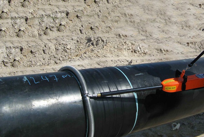
Corrosion Protection Coating Three Layer Polyethylene (3LPE) coating
Three Layer Polypropylene (3LPP) coating
Fusion bonded epoxy (FBE) coating
– Coal tar enamel (CTE) Coating
Painting Coatings such as:
– Coal Tar Enamel Coating (CTE)
Three-layer polyethylene coating (3LPE)
Three-layer polypropylene coating (3LPP)
– Double-layer fusion bonded epoxy coating (2FBE)
Painting
Cathodic Protection System – Impressed Current Cathodic Protection (ICCP) system
– Sacrificial Anode (limited locations)
Not applicable Sacrificial Anodic Cathodic Protection (SACP) system Непригодный
Hydrostatic testing – Gauge Plate run of 95% of the ID of the highest pipe thickness
– Test Pressure
Minimum: 1.25 times of Design Pressure (for liquid pipelines)
1.25 to 1.5 times of Design Pressure (for gas pipelines)
Maximum: Pressure equivalent to Hoop stress of 95% of SMYS of pipe material
– Hold period: 24 hours
– No gauge plate run is done. Generally, cardboard blasting is done to clean the piping.
– Test Pressure
Minimum: 1.5 × Design Pressure × Temperature Factor
Maximum: Based on line schedule
– Hold period: 2 – 6 hours
– Gauge Plate run of 95% of the ID of the highest pipeline thickness.
– Test Pressure
Minimum: 1.25 times x Design Pressure
– Hold period: 24 hours
– No gauging is done.
– Test Pressure
Maximum: As per line schedule
– Hold period: 2 hours
Preservation – Preservation of pipeline with corrosion-inhibited water or by filling of inert gas (N2) Not applicable
Pigging Intelligent Pigging Not applicable Compliant Not applicable
Machines/Equipment required for installation – Trencher
– Backhoe/ Excavator
– Side Boom
– Cold field bending machine
– Holiday Detection Machines
– Pneumatic/ Hydraulic Internal Clamps
Crane/ Hydra – Pipelay Barge
– Derrick Barge
– Diving support vessel
– Dynamic Positioning (DP) barge (for deepwater)
Pre-fabricated deck piping

Conclusion: Onshore vs Offshore Pipeline and Piping

In summary, Onshore pipelines are usually buried or erected on land to transport oil, natural gas, drinking water, sewage, seawater, slurry, etc. Onshore piping is typically erected in petrochemical plants, power plants, refineries, fire protection systems, water treatment systems, etc., while Offshore pipelines are buried on the seabed. Offshore piping typically consists of transmission and structural support pipeline systems on offshore drilling platforms. Special offshore equipment includes underwater isolation valves, tees, and submarine hoses. Offshore surveys include geophysics, bathymetry, and ocean data collection, while onshore surveys focus on topographic and geotechnical engineering studies.

L80-9Cr vs L80-13Cr

L80-9Cr vs L80-13Cr: Something You Need to Know

Choosing the proper casing and tubing materials can ensure safety and efficiency in oil and gas drilling and exploration. L80-9Cr and L80-13Cr are two alloy steel grades commonly used in petroleum casing and tubing. Each grade has unique characteristics and applications. L80-9Cr vs L80-13Cr, this article will delve into the difference between these materials to help you make an informed decision.

1. Overview of L80 Grade

L80 is an alloy steel used in the oil and gas sector. It is known for its good strength and corrosion resistance. It is typically employed in high-temperature and high-pressure environments and is suitable for both oil and gas production.

1.1 L80-9Cr

Composition: Contains 9% chromium, enhancing the material’s oxidation resistance at high temperatures.
Характеристики:
Corrosion Resistance: It performs well in CO2 environments, making it suitable for acidic gas pipelines.
Mechanical Strength: Provides good strength and is suitable for high-temperature operations.
Applications: Commonly used in high-temperature gas pipelines in oil fields.

1.2 L80-13Cr

Composition: Contains 13% chromium, offering higher corrosion resistance.
Характеристики:
Corrosion Resistance: Exhibits superior performance in environments with H2S and CO2, suitable for extreme conditions.
Mechanical Strength: Offers higher strength and is ideal for complex operational environments.
Applications: Used in high-corrosion environments and deep well operations.

L80-9Cr vs L80-13Cr

L80-9Cr and L80-13Cr Casing and Tubing in Oil and Gas Drilling and Exploration

2. Comparison: L80-9Cr vs L80-13Cr

2.1 Chemical Composition

Стандартный Оценка С Си Мин. п С Кр Мо Ни Cu
API 5CT L80-9Cr ≤ 0,15 ≤ 1.00 0.30-0.60 ≤ 0,020 ≤ 0,010 8.00-10.00 0.90-1.10 ≤ 0.50 ≤ 0,25
L80-13Cr 0.15-0.22 ≤ 1.00 0.25-1.00 ≤ 0,020 ≤ 0,010 12.00-14.00 ≤ 0.50 ≤ 0,25

2.2 Механические свойства

Стандартный Оценка Yield Strength (Mpa) Предел прочности (МПа) Удлинение (%) Hardness max
мин. max. мин. мин. СПЧ HBW
API 5CT L80-9Cr 552 655 655 API 5CT
Table C.7
23 241
L80-13Cr 552 655 655 23 241

2.3 Impact Test

Стандартный Оценка Sharpy Impact Energy (J)
Coupling Тело трубы
API 5CT L80-9Cr L-10-40-0 T-10-20-0 L-10-27-0 T-10-14-0
L80-13Cr L-10-40-0 T-10-20-0 L-10-27-0 T-10-14-0

2.4 Corrosion Resistance

L80-9Cr: The 9% chromium content provides moderate corrosion resistance, suitable for environments with low to moderate concentrations of H₂S (hydrogen sulfide) or CO₂ (carbon dioxide), typically seen in less aggressive environments.

L80-13Cr: The 13% chromium content provides enhanced resistance to sour service (i.e., environments with high levels of H₂S) and high CO₂ environments. It’s better for harsher conditions like deep wells or offshore drilling.

2.5 Temperature and Sour Service

L80-9Cr: Generally suitable for moderate-temperature environments.

L80-13Cr: Can withstand higher temperatures and is better equipped for sour service conditions with high concentrations of H₂S or CO₂.

2.6 Cost

L80-9Cr: Due to its lower chromium content, L80-9Cr is less expensive than L80-13Cr. If the environment is not highly corrosive or sour, L80-9Cr could be a more cost-effective option.

L80-13Cr: More expensive but provides superior resistance in harsh conditions, potentially reducing maintenance costs or failures over time.

2.7 Applications

L80-9Cr: Suitable in wells with moderate temperature, pressure, and sour gas conditions. Often used in conventional oil and gas wells or less aggressive service environments.

L80-13Cr: Ideal for high-pressure wells with harsh environmental conditions, particularly in sour gas service, deep wells, or offshore oil & gas operations where high corrosion resistance is critical.

Ветровые турбины для оффшорных установок

Конструкционные круглые полые секции для наземных и морских ветровых турбин

Поскольку спрос на возобновляемую энергию продолжает расти во всем мире, морская ветроэнергетика стала жизненно важным решением. В этой статье рассматривается значение структурных круглых полых секций (CHS), используемых в опорных конструкциях морских ветровых турбин, исследуются их конструкция, свойства материалов и области применения.

1. Понимание структурных круглых полых сечений

Конструкционные круглые полые профили представляют собой цилиндрические трубы с полым центром. Эти секции играют важную роль в опорных конструкциях морских ветровых турбин, которые в первую очередь предназначены для выдерживания веса турбины и выдерживания внешнего давления окружающей среды.

2. Свойства материалов конструкционных круглых полых профилей

Углеродистая сталь: S355MH, S355MLH, S420MH, S420MLH, S460MH, S460MLH, S460QH, S460QLH, S620QH, S620QLH, S690QH, S690QLH

3. Вопросы проектирования

При проектировании опорных конструкций для морских ветряных турбин необходимо учитывать ряд факторов:
Ветровая нагрузка: Турбины во время работы подвергаются динамическим нагрузкам от ветра, поэтому необходима конструкция, обеспечивающая структурную устойчивость.
Воздействие волн: Волны в морской среде оказывают дополнительное давление на конструкции, что требует тщательного расчета и корректировки проекта.
Защита от коррозии: Учитывая коррозионную активность морской воды, использование защитных покрытий или коррозионно-стойких материалов имеет решающее значение для продления срока службы конструкции.

4. Преимущества использования круглых полых профилей

Использование круглых полых профилей в опорных конструкциях дает ряд преимуществ:
Высокая прочность на сжатие: круглое поперечное сечение обеспечивает равномерное распределение давления, повышая общую устойчивость.
Легкость: по сравнению с другими формами круглые трубы обеспечивают аналогичную прочность при меньшем весе, что облегчает транспортировку и установку.
Простота строительства: Простота соединения и сварки круглых труб повышает эффективность строительства.

5. Часто задаваемые вопросы

В: Какой материал следует выбрать для конструкционных круглых полых профилей?
А: Выбор материала зависит от конкретных условий окружающей среды, бюджета и требований к конструкции. Углеродистая сталь подходит для большинства применений, но в высококоррозионных средах более подходящей может оказаться нержавеющая сталь или легированная сталь.

В: Как обеспечить долговечность конструкционных круглых полых профилей?
А: Регулярные проверки и техническое обслуживание имеют решающее значение для обеспечения долговечности. Кроме того, выбор соответствующих защитных покрытий и материалов может значительно продлить срок службы конструкций.

6. Заключение

Структурные круглые полые секции незаменимы в опорных конструкциях морских ветровых турбин. Благодаря тщательному проектированию и выбору материалов ветровые турбины могут быть улучшены в плане стабильности и долговечности, тем самым способствуя развитию возобновляемой энергетики.

Для получения дополнительных запросов или помощи относительно конструкционных полых секций для наземных и морских ветровых турбин обращайтесь по адресу [email protected].

Производство сырой стали

Производство стали в сентябре 2024 г.

В сентябре 2024 года мировое производство стали в 71 стране, предоставившей отчеты Всемирной ассоциации производителей стали (World Steel Association), составило 143,6 млн тонн (Мт), что на 4,7% меньше, чем в сентябре 2023 года.

производство сырой стали

производство сырой стали

Производство стали по регионам

Африка произвела 1,9 млн тонн в сентябре 2024 года, что на 2,6% больше, чем в сентябре 2023 года. Азия и Океания произвели 105,3 млн тонн, что на 5,0% меньше. ЕС (27) произвел 10,5 млн тонн, что на 0,3% больше. Европа, другие произвели 3,6 млн тонн, что на 4,1% больше. Ближний Восток произвел 3,5 млн тонн, что на 23,0% меньше. Северная Америка произвела 8,6 млн тонн, что на 3,4% меньше. Россия и другие страны СНГ + Украина произвели 6,8 млн тонн, что на 7,6% меньше. Южная Америка произвела 3,5 млн тонн, что на 3,3% больше.

Таблица 1. Производство стали по регионам

Область Сентябрь 2024 (Мт) % изменение 24/23 сен Янв-Сент 2024 (Мт) % изменение янв.-сент. 24/23
Африка 1.9 2.6 16.6 2.3
Азия и Океания 105.3 -5 1,032.00 -2.5
ЕС (27) 10.5 0.3 97.8 1.5
Европа, Другое 3.6 4.1 33.1 7.8
Средний Восток 3.5 -23 38.4 -1.5
Северная Америка 8.6 -3.4 80 -3.9
Россия и другие страны СНГ + Украина 6.8 -7.6 64.9 -2.5
Южная Америка 3.5 3.3 31.4 0
Всего 71 страна 143.6 -4.7 1,394.10 -1.9

На 71 страну, включенную в эту таблицу, пришлось около 981 трлн. тонн от общего мирового производства нерафинированной стали в 2023 году.

Регионы и страны, охваченные таблицей:

  • Африка: Алжир, Египет, Ливия, Марокко, Южная Африка, Тунис
  • Азия и Океания: Австралия, Китай, Индия, Япония, Монголия, Новая Зеландия, Пакистан, Южная Корея, Тайвань (Китай), Таиланд, Вьетнам
  • Европейский Союз (27): Австрия, Бельгия, Болгария, Хорватия, Чехия, Финляндия, Франция, Германия, Греция, Венгрия, Италия, Люксембург, Нидерланды, Польша, Португалия, Румыния, Словакия, Словения, Испания, Швеция
  • Европа, Другое: Македония, Норвегия, Сербия, Турция, Соединенное Королевство
  • Средний Восток: Бахрейн, Иран, Ирак, Иордания, Кувейт, Оман, Катар, Саудовская Аравия, Объединенные Арабские Эмираты, Йемен
  • Северная Америка: Канада, Куба, Сальвадор, Гватемала, Мексика, США.
  • Россия и другие страны СНГ + Украина: Беларусь, Казахстан, Россия, Украина
  • Южная Америка: Аргентина, Бразилия, Чили, Колумбия, Эквадор, Парагвай, Перу, Уругвай, Венесуэла

10 крупнейших стран-производителей стали

Китай произвел 77,1 млн тонн в сентябре 2024 года, что на 6,1% меньше, чем в сентябре 2023 года. Индия произвела 11,7 млн тонн, что на 0,2% меньше. Япония произвела 6,6 млн тонн, что на 5,8% меньше. США произвели 6,7 млн тонн, что на 1,2% больше. Россия, по оценкам, произвела 5,6 млн тонн, что на 10,3% меньше. Южная Корея произвела 5,5 млн тонн, что на 1,3% больше. Германия произвела 3,0 млн тонн, что на 4,3% больше. Турция произвела 3,1 млн тонн, что на 6,5% больше. Бразилия произвела 2,8 млн тонн, что на 9,9% больше. Иран, по оценкам, произвел 1,5 млн тонн, что на 41,2% меньше.

Таблица 2. Десять крупнейших стран-производителей стали

Область  Сентябрь 2024 (Мт) % изменение 24/23 сен Янв-Сент 2024 (Мт) % изменение янв.-сент. 24/23
Китай 77.1 -6.1 768.5 -3.6
Индия 11.7 -0.2 110.3 5.8
Япония 6.6 -5.8 63.3 -3.2
Соединенные Штаты 6.7 1.2 60.3 -1.6
Россия 5.6 е -10.3 54 -5.5
Южная Корея 5.5 1.3 48.1 -4.6
Германия 3 4.3 28.4 4
Türkiye 3.1 6.5 27.9 13.8
Бразилия 2.8 9.9 25.2 4.4
Иран 1,5 е -41.2 21.3 -3.1

e – оценка. Рейтинг 10 крупнейших стран-производителей основан на совокупном годовом показателе

API 5L против ISO 3183

Узнайте различия: API 5L и ISO 3183

ISO 3183 и API 5L — это стандарты, относящиеся к стальным трубам, в первую очередь для использования в нефтяной, газовой и других отраслях транспортировки жидкостей. Хотя между этими двумя стандартами, API 5L и ISO 3183, есть значительное совпадение, существуют ключевые различия в их области применения, применении и организациях, стоящих за ними.

1. Организации-эмитенты: API 5L против ISO 3183

API 5L: Этот стандарт, выпущенный Американским институтом нефти (API), в основном используется в нефтегазовой промышленности. Он подробно описывает технические требования к стальным трубам, транспортирующим нефть, газ и воду.
ISO 3183: Этот стандарт, выпущенный Международной организацией по стандартизации (ISO), признан на международном уровне и используется во всем мире для стальных труб в секторе транспортировки нефти и газа.

2. Область применения: API 5L против ISO 3183

API 5L: Охватывает стальные трубы для транспортировки нефти, природного газа и других жидкостей под высоким давлением. Широко используется в Северной Америке, особенно в Соединенных Штатах.
ISO 3183: Этот стандарт в первую очередь ориентирован на проектирование, производство и контроль качества стальных труб, используемых в нефте- и газопроводах, но его применение носит более международный характер и применяется в различных странах мира.

3. Основные различия: API 5L и ISO 3183

Географический и рыночный фокус:

API 5L больше ориентирован на североамериканский рынок (в частности, США), в то время как ISO 3183 применяется на международном уровне и используется во многих странах мира.

Марки стали и требования:

API 5L определяет такие марки стали, как L175, L210, L245 и т. д., где число представляет собой минимальный предел текучести в мегапаскалях (МПа).
Стандарт ISO 3183 также определяет аналогичные марки, но с более подробными требованиями к свойствам материалов, производственным процессам и протоколам контроля, что соответствует международной отраслевой практике.
Дополнительные характеристики:
API 5L уделяет особое внимание контролю качества, сертификации и производственным требованиям, тогда как ISO 3183 охватывает более широкую сферу, учитывая международную торговлю, и содержит спецификации для различных условий, включая температуру, окружающую среду и особые механические требования.

4. Технические требования: API 5L против ISO 3183

API 5L определяет свойства материала стальных труб, производственные процессы, размеры, методы испытаний и контроль качества. Он определяет марки стали от L (низкая прочность) до X (высокая прочность), такие как X42, X60 и X70.
ISO 3183 охватывает аналогичные аспекты производства стальных труб, включая качество материала, термическую обработку, обработку поверхности и концы труб. Он также содержит подробные спецификации для проектного давления трубопровода, экологических соображений и различных трубопроводных принадлежностей.

5. Сравнение марок труб: API 5L и ISO 3183

API 5L: Классы варьируются от класса L (низкий предел текучести) до класса X (высокий предел текучести). Например, X60 относится к трубам с пределом текучести 60 000 фунтов на квадратный дюйм (приблизительно 413 МПа).
ISO 3183: Он использует похожую систему градации, но может включать более подробные классификации и условия. Он также обеспечивает соответствие мировым практикам проектирования и эксплуатации трубопроводов.

6. Совместимость стандартов:

Во многих случаях API 5L и ISO 3183 совместимы, что означает, что стальная труба, которая соответствует требованиям API 5L, как правило, также будет соответствовать требованиям ISO 3183 и наоборот. Однако конкретные проекты трубопроводов могут придерживаться одного стандарта по сравнению с другим в зависимости от местоположения, предпочтений клиента или нормативных требований.

7. Заключение:

API 5L более распространен в Соединенных Штатах и близлежащих регионах. Он ориентирован на нефте- и газопроводную отрасль, уделяя особое внимание контролю производства и качества.
ISO 3183 — международный стандарт для глобальных проектов по строительству нефте- и газопроводов. Его более подробные, глобально согласованные требования обеспечивают более широкое признание на международных рынках.

Оба стандарта очень похожи в отношении спецификаций материалов, производства и испытаний. Тем не менее, ISO 3183 имеет тенденцию иметь более широкую, более глобально применимую область применения, в то время как API 5L остается более специфичным для североамериканского рынка. Выбор между этими стандартами зависит от географического положения проекта трубопровода, спецификаций и нормативных потребностей.