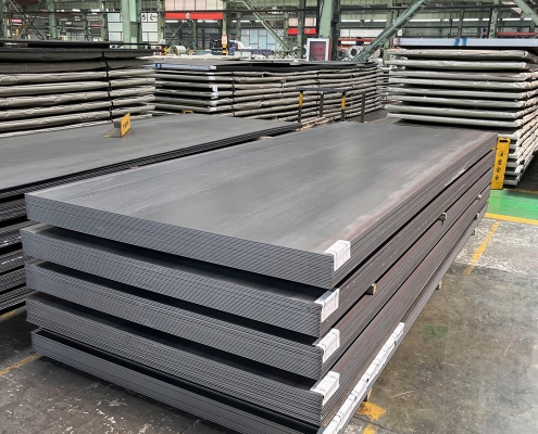
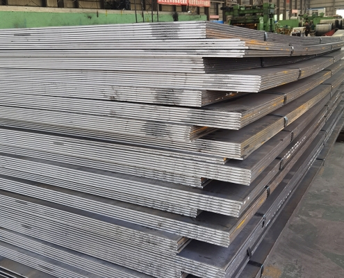
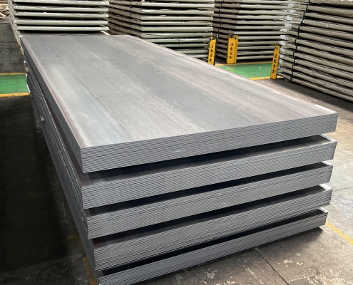
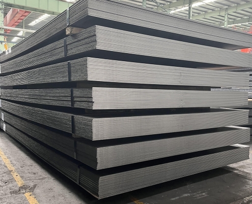
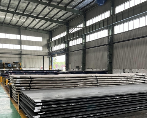
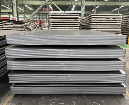
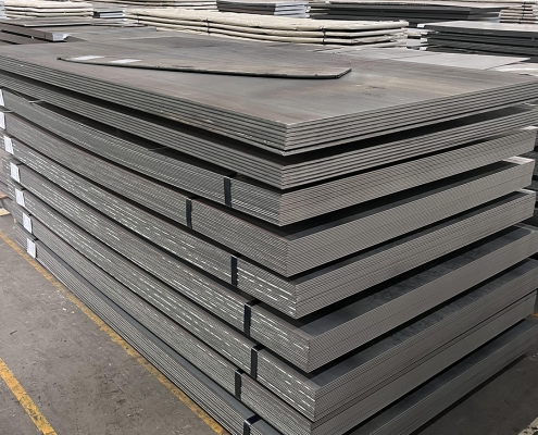
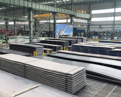
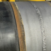
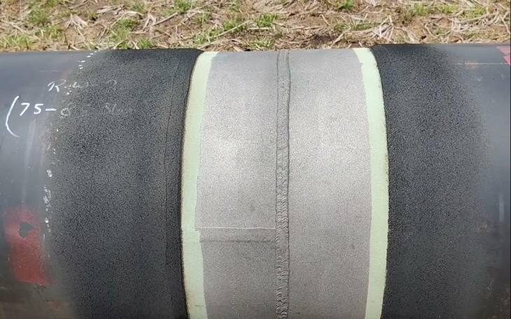
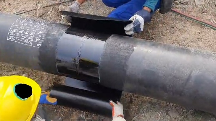
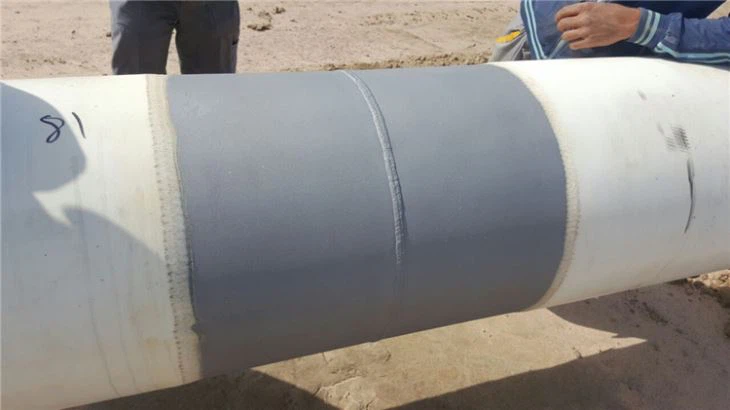
ZAM Coated Steel for Photovoltaic Brackets

Zinc-Aluminum-Magnesium (ZAM) vs Hot-dip galvanizing (HDG)

Definicja

What is Zinc-Aluminum-Magnesium (ZAM)?

Zinc-aluminum-magnesium (ZAM) is a high-performance metallic coating applied to steel designed to offer superior corrosion resistance, durability, and heat resistance compared to traditional galvanizing (zinc-only coatings). The coating combines zinc (Zn), aluminum (Al), and magnesium (Mg), which provides unique advantages in various applications.

ZAM Coating

ZAM Coating

What is Hot-dip galvanizing? (HDG)?

Hot-dip galvanization is a form of galvanization. It is the process of coating iron and steel with zinc, which alloys with the base metal surface when immersing the metal in a bath of molten zinc at a temperature of around 450 °C (842 °F). When exposed to the atmosphere, the pure zinc (Zn) reacts with oxygen (O2) to form zinc oxide (ZnO), which further reacts with carbon dioxide (CO2) to form zinc carbonate (ZnCO3), a usually dull grey, fairly strong material that protects the steel underneath from further corrosion in many circumstances.

Hot-dip Galvanizing

Hot-dip Galvanizing

Main Differences: Zinc-Aluminum-Magnesium (ZAM) vs Hot-dip galvanizing (HDG)

The comparison between zinc-aluminum-magnesium (ZAM) I hot-dip galvanizing (HDG) revolves around their coating composition, corrosion resistance, applications, cost, I environmental impact. Below is a detailed comparison to help understand their differences:

1. Coating Composition

Zinc-Aluminum-Magnesium (ZAM):
ZAM coatings are made of a combination of zinc (Zn), aluminum (Al), I magnesium (Mg). Typically, the composition is about 80-90% Zinc, 5-11% Aluminum, I 1-3% Magnesium. Including aluminum and magnesium gives the coating superior properties compared to zinc alone.

Hot-Dip Galvanizing (HDG):
HDG involves immersing steel into a molten bath of zinc (Zn) to form a protective zinc coating. The coating consists almost entirely of zinc, with small amounts of iron from the substrate, forming a zinc-iron alloy layer.

2. Odporność na korozję

Zinc-Aluminum-Magnesium (ZAM):
Superior corrosion resistance compared to hot-dip galvanized steel. Adding aluminum increases the coating’s resistance to high temperatures and oxidation, while magnesium improves its resistance to corrosion in harsh environments like coastal, industrial, and chemical settings. ZAM has self-healing properties—if the coating is damaged, the magnesium component reacts with moisture to help prevent further corrosion.

Hot-Dip Galvanizing (HDG):
It provides good corrosion resistance but not as high as ZAM, especially in aggressive environments. The zinc coating is sacrificial, meaning it corrodes first to protect the underlying steel, but its effectiveness can be limited in humid, salty, Lub chemical environments. HDG does not have the advanced self-healing properties that ZAM offers.

3. Durability and Longevity

Zinc-Aluminum-Magnesium (ZAM):
ZAM-coated products can last 2 to 4 times longer than traditional galvanized steel in harsh environments (e.g., coastal areas, chemical plants, etc.). The coating’s enhanced resistance to environmental factors contributes to a longer service life.

Hot-Dip Galvanizing (HDG):
The lifespan of HDG products is good but generally shorter than ZAM, particularly in extreme conditions. HDG can last for many years in less corrosive environments (e.g., mild climates), but its protection may degrade faster in severe environments.

4. Applications

Zinc-Aluminum-Magnesium (ZAM):
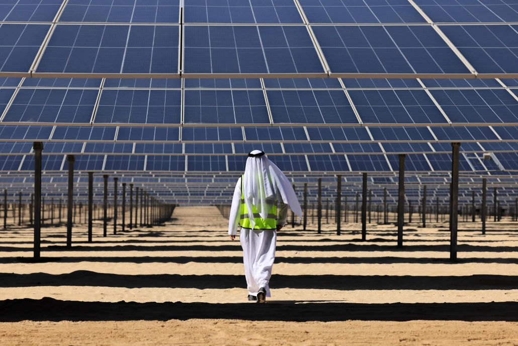
Ideal for trudne warunki such as Coastal areas (where saltwater exposure is high), Chemical and industrial environments (where exposure to aggressive substances is every day), Solar panel mounts (due to its superior durability), Heavy-duty industrial applications (e.g., agricultural and mining equipment, steel structures exposed to extreme weather conditions).

Hot-Dip Galvanizing (HDG):
It is commonly used in general construction, automotive industries, outdoor infrastructure, I agricultural applications. It is suitable for general-purpose corrosion protection in outdoor conditions but not recommended for extreme or coastal environments.

5. Cost

Zinc-Aluminum-Magnesium (ZAM):
It is more expensive than traditional hot-dip galvanizing due to the inclusion of aluminum and magnesium and the more advanced coating process. The longer lifespan and lower maintenance costs in harsh environments often justify the higher initial cost.

Hot-Dip Galvanizing (HDG):
It is cheaper than ZAM, making it more suitable for projects where cost-efficiency is a priority and the environment is less aggressive. The relatively lower cost makes it ideal for large-scale production.

6. Environmental Impact

Zinc-Aluminum-Magnesium (ZAM):
The production of ZAM coatings is more environmentally friendly than hot-dip galvanizing, as it involves lower emissions of harmful gases and waste materials. The production process for ZAM generally generates less waste I fewer harmful emissions compared to traditional galvanizing methods.

Hot-Dip Galvanizing (HDG):
It is more environmentally intensive than ZAM, producing more waste gases and wastewater. However, modern improvements in the HDG process have aimed to reduce the environmental footprint, though it remains higher than ZAM.

7. Aesthetic Appearance

Zinc-Aluminum-Magnesium (ZAM):
ZAM has a matte gray finish with a smoother, more uniform appearance. This appearance can be more desirable in specific applications like architectural structures or solar panel mounts.

Hot-Dip Galvanizing (HDG):
HDG often has a shiny or dull metallic finish, depending on the thickness of the coating. While durable, its aesthetic appearance may be less appealing than ZAM’s, especially if the finish is uneven.

8. Ease of Processing and Welding

Zinc-Aluminum-Magnesium (ZAM):
ZAM coatings can be more challenging to process, weld, I paint than traditional galvanized steel, creating issues in some applications.

Hot-Dip Galvanizing (HDG):
HDG products are easier to weld and process than ZAM. However, the zinc coating can make welding and cutting more difficult due to zinc fumes, and special precautions may be required.

Summary Comparison Table: Zinc-Aluminum-Magnesium (ZAM) vs Hot-dip Galvanizing (HDG)

Funkcja Zinc-Aluminum-Magnesium (ZAM) Hot-Dip Galvanizing (HDG)
Coating Composition Zinc, Aluminum, Magnesium Zinc (with some iron from the substrate)
Odporność na korozję Superior, especially in harsh environments Good, but less effective in aggressive settings
Durability and Longevity 2-4 times longer than HDG in extreme environments Moderate lifespan, shorter in harsh conditions
Aplikacje Coastal areas, chemical environments, heavy-duty General outdoor infrastructure, agriculture
Koszt Higher initial cost Lower initial cost
Wpływ środowiska Lower emissions and waste Higher emissions and waste
Aesthetic Appearance Matte gray, smoother finish Shiny or dull metallic finish
Ease of Processing It can be more challenging, especially with welding It is more straightforward to process and weld

Wniosek

ZAM is the best choice for extreme environments where superior corrosion resistance and durability are needed. Its long-term performance can justify the higher upfront cost.

HDG remains the go-to solution for general corrosion protection in less aggressive environments, providing a cost-effective and widely available option for most standard applications.

Pipeline vs Piping

Onshore vs Offshore Pipeline and Piping

Wstęp

In the realm of energy transportation, the distinction between onshore and offshore pipelines and piping systems plays a crucial role in the efficiency, safety, and environmental impact of resource extraction and distribution. Onshore pipelines, typically situated on land, are designed to transport oil, gas, and other fluids over varying distances, benefiting from relatively more straightforward access for maintenance and monitoring. Conversely, offshore pipelines, laid on the seabed or suspended in water, present unique engineering challenges due to harsh marine conditions and logistical complexities. Understanding the Onshore vs Offshore Pipeline and Piping in design, construction, and operational considerations between these two types of pipelines is essential for optimizing infrastructure development and ensuring sustainable practices in the energy sector.

Definition: Onshore vs Offshore Pipeline and Piping

What is Pipeline?

Pipeline is a long series of pipes, usually of large diameter, running underground, aboveground and underwater, such as a submarine pipeline, and equipped with fittings, such as valves and pumps, to control the flow of large quantities of fluid over long distances. Pipelines have large diameters, making it easy to transport liquids or gases in bulk from one place to another, sometimes for thousands of miles.

Pipeline

Pipeline

What is Piping?

Rurociąg is a system of pipes used to convey fluids (liquids and gases) from one location to another within the designated boundaries or spaces of petrochemical plants, power plants, refineries, etc. It is also equipped with valves and fittings to control the flow of fluids from one facility to another as needed, but only within the plant’s designated boundaries. Never skip these essential topics when taking an online course on piping engineering. Piping diameters range from 1/2 inch to 80 inches, depending on the facility’s design requirements for fluid transportation, usually from one facility to another within the facility’s boundaries.

Rurociąg

Rurociąg

What is Onshore Pipeline?

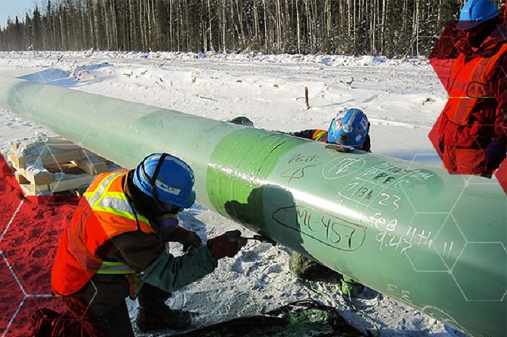
Onshore pipelines refer to networks of pipelines and related equipment used to transport fluids such as oil, natural gas, water, and chemicals in a land environment. These pipelines are integral to long-distance oil and gas transportation from oil fields to refineries, from natural gas wells to gas stations, and from crude oil and refined oil tank farms, chemical tank farms, LNG tank farms, and aircraft refueling pipeline operations.

Onshore Pipeline

Onshore Pipeline

What is Offshore Pipeline?

Offshore pipelines refer to the network of pipes and related equipment used to transport fluids such as oil, gas, water, and chemicals in an offshore environment. These pipelines are integral to operating offshore oil rigs, platforms and floating production storage and offloading units (FPSOs). The unique conditions of the offshore environment, such as high salinity, extreme temperatures, and strong currents, present significant challenges to the design and maintenance of these systems.

Offshore Pipeline

Offshore Pipeline

Main Differences: Onshore vs Offshore Pipeline and Piping

Comparison Table: Onshore vs Offshore Pipeline and Piping

Specyfikacja Na brzegu Na morzu
Pipeline Rurociąg Pipeline Rurociąg
Kody projektowe – ASME B31.4: Pipeline Transportation Systems for Liquids and Slurries
– ASME B31.8: Gas Transmission and Distribution Piping Systems
ASME B31.3: Process Piping – DNVGL-ST-F101: Submarine pipeline systems
– API RP 1111: Design, Construction, Operation, and Maintenance of Offshore Hydrocarbon Pipelines (Limit state design)
ASME B31.3: Process Piping
Zakres Outside plant boundary
(Villages, fields, rivers, canals, railways, highways, cities, deserts, forests, hills, etc.)
Within plant boundary Outside plant boundary Within plant boundary
Type of pipe API Spec 5L: Specification for Line pipes – ASTM
– BS
– API 5L
API Spec 5L: Specification for Line pipes
– DNVGL-ST-F101: Submarine Pipeline Systems
Normy ASTM
Zawory – API 6D: Specification for Pipeline and Piping Valves
– Full Bore (FB) Ball Valves are used for pigs.
– BS
– API Standard
– Full bore (FB) and Reduced bore (RB)
– Full bore Valves: for smooth passage of intelligent pigs
– API 6D SS: Specification on Subsea Pipeline Valves
– RB valves
– BS/API standards
Spawalniczy – API Std. 1104: Welding of Pipelines and Related Facilities
– Type of welding: Automatic / Semi-Automatic/ Manual
– ASME Sec. IX: Standard for Welding and Brazing Procedures, Welders, Brazers and Welding and Brazing Operators
– Type of welding: Manual (mostly)
– API Std. 1104: Welding of Pipelines and Related Facilities
– Mostly automatic welding on pipelay barge.
– ASME Sec. IX: Standard for Welding and Brazing Procedures, Welders, Brazers and Welding and Brazing Operators
– Manual welding at the fabrication yard.
Weld joint inspection (NDT requirements) 100% by Automatic UT or RT (by using X-Ray) 5% to 100%
(mostly by using gamma rays)
100% by Automatic UT From 10% to 100% as required
Analyses – Wall Thickness Analysis
– Elastic Bend Radius Analysis
– Stability Analysis for Water Bodies/ Marshy Areas
– Horizontal directional drilling design analysis
– Railroad/ Highway Crossing Analysis
– Casing Pipe Analysis for Crossings
– Seismic Analysis
– Piping wall thickness calculation
– Piping Stress Analysis
Static Analysis
Dynamic Analysis
Wind Analysis
Flange Leakage Analysis
Seismic Analysis
– Wall thickness Analysis
– On-bottom Stability
– Span Analysis
– Global Buckling – Lateral and Upheaval
– Pipeline Expansion Analysis
– Riser Design (Span, Stress & Flexibility Analysis)
– Riser Clamp Design
– Pipeline Crossing Design and Analysis
– Deck piping stress analysis
Instalacja Buried (mostly) Above ground/On rack/slippers/T-postal etc. Subsea (in water on the seabed or buried in the seabed) Deck Platform Piping
(similar to plant)
Special Installations – Across rivers
– Horizontal Directional Drilling (HDD) method
– Micro-tunnelling method
– Across road/ rail/ highway
– Auger boring/ jacking boring method
– Shallow HDD
– Ghats/ Hills
– Modular installations
– Finning
– Studding
– Jacketing
– Spooling inside warehouse
– U/G piping for cooling water
– S-lay Method (for shallow water installation)
– J-Lay Method (for deep water installation)
– Shore pull/ barge pull near Land Fall Point (LFP)
Along with the deck structure
Special Equipment – Sectionalizing Valves (Remote operated)
– Insulating Joints
– Scraper Launcher/ Receiver
– Stem Extended Valves (for buried valves)
– Flow Tee
– Long Radius bends (R=6D)
– Cold field bends (R = 30D or 40D)
– Expansion Joints
– Motor Operator Valves (MOV)
– Cryogenic Valves
– Springs
– Subsea Isolation Valve (SSIV)
– LR Bends
– Flow tee
– Pipeline End Manifold (PLEM)
– Single Point Mooring (SPM) system
– Submarine hoses
– Floating hoses
– Cables and umbilical installation
– Piggy-back pipelines
Nie dotyczy
Survey – Topographical Survey
(all along the pipeline route)
– Geotechnical investigation
(all along the pipeline route)
– Soil resistivity survey
(all along the pipeline route)
– Hydrological Survey for water bodies (for scour depth calculation)
– Cadastral Survey (for RoU acquisition)
– Wind profile from meteorology
– Seismic study of plot
– Geophysical survey/ Bathymetric Survey by using side scan sonar, sub-bottom profiler, and echo-sounder
– Met-Ocean data collection
– Geotechnical data of the pipeline route
Nie dotyczy
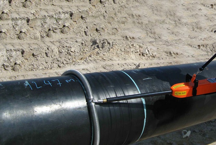
Corrosion Protection Coating Three Layer Polyethylene (3LPE) coating
Three Layer Polypropylene (3LPP) coating
Fusion bonded epoxy (FBE) coating
– Coal tar enamel (CTE) Coating
Painting Coatings such as:
– Coal Tar Enamel Coating (CTE)
Three-layer polyethylene coating (3LPE)
Three-layer polypropylene coating (3LPP)
– Double-layer fusion bonded epoxy coating (2FBE)
Painting
Cathodic Protection System – Impressed Current Cathodic Protection (ICCP) system
– Sacrificial Anode (limited locations)
Not applicable Sacrificial Anodic Cathodic Protection (SACP) system Nie dotyczy
Hydrostatic testing – Gauge Plate run of 95% of the ID of the highest pipe thickness
– Test Pressure
Minimum: 1.25 times of Design Pressure (for liquid pipelines)
1.25 to 1.5 times of Design Pressure (for gas pipelines)
Maximum: Pressure equivalent to Hoop stress of 95% of SMYS of pipe material
– Hold period: 24 hours
– No gauge plate run is done. Generally, cardboard blasting is done to clean the piping.
– Test Pressure
Minimum: 1.5 × Design Pressure × Temperature Factor
Maximum: Based on line schedule
– Hold period: 2 – 6 hours
– Gauge Plate run of 95% of the ID of the highest pipeline thickness.
– Test Pressure
Minimum: 1.25 times x Design Pressure
– Hold period: 24 hours
– No gauging is done.
– Test Pressure
Maximum: As per line schedule
– Hold period: 2 hours
Preservation – Preservation of pipeline with corrosion-inhibited water or by filling of inert gas (N2) Not applicable
Pigging Intelligent Pigging Not applicable Compliant Not applicable
Machines/Equipment required for installation – Trencher
– Backhoe/ Excavator
– Side Boom
– Cold field bending machine
– Holiday Detection Machines
– Pneumatic/ Hydraulic Internal Clamps
Crane/ Hydra – Pipelay Barge
– Derrick Barge
– Diving support vessel
– Dynamic Positioning (DP) barge (for deepwater)
Pre-fabricated deck piping

Conclusion: Onshore vs Offshore Pipeline and Piping

In summary, Onshore pipelines are usually buried or erected on land to transport oil, natural gas, drinking water, sewage, seawater, slurry, etc. Onshore piping is typically erected in petrochemical plants, power plants, refineries, fire protection systems, water treatment systems, etc., while Offshore pipelines are buried on the seabed. Offshore piping typically consists of transmission and structural support pipeline systems on offshore drilling platforms. Special offshore equipment includes underwater isolation valves, tees, and submarine hoses. Offshore surveys include geophysics, bathymetry, and ocean data collection, while onshore surveys focus on topographic and geotechnical engineering studies.

L80-9Cr vs L80-13Cr

L80-9Cr vs L80-13Cr: Something You Need to Know

Choosing the proper casing and tubing materials can ensure safety and efficiency in oil and gas drilling and exploration. L80-9Cr and L80-13Cr are two alloy steel grades commonly used in petroleum casing and tubing. Each grade has unique characteristics and applications. L80-9Cr vs L80-13Cr, this article will delve into the difference between these materials to help you make an informed decision.

1. Overview of L80 Grade

L80 is an alloy steel used in the oil and gas sector. It is known for its good strength and corrosion resistance. It is typically employed in high-temperature and high-pressure environments and is suitable for both oil and gas production.

1.1 L80-9Cr

Composition: Contains 9% chromium, enhancing the material’s oxidation resistance at high temperatures.
Charakterystyka:
Corrosion Resistance: It performs well in CO2 environments, making it suitable for acidic gas pipelines.
Mechanical Strength: Provides good strength and is suitable for high-temperature operations.
Applications: Commonly used in high-temperature gas pipelines in oil fields.

1.2 L80-13Cr

Composition: Contains 13% chromium, offering higher corrosion resistance.
Charakterystyka:
Corrosion Resistance: Exhibits superior performance in environments with H2S and CO2, suitable for extreme conditions.
Mechanical Strength: Offers higher strength and is ideal for complex operational environments.
Applications: Used in high-corrosion environments and deep well operations.

L80-9Cr vs L80-13Cr

L80-9Cr and L80-13Cr Casing and Tubing in Oil and Gas Drilling and Exploration

2. Comparison: L80-9Cr vs L80-13Cr

2.1 Chemical Composition

Standard Stopień C Si Mn P S Kr Pon Ni Cu
API5CT L80-9Cr ≤ 0,15 ≤ 1.00 0.30-0.60 ≤ 0,020 ≤ 0,010 8.00-10.00 0.90-1.10 ≤ 0.50 ≤ 0,25
L80-13Cr 0.15-0.22 ≤ 1.00 0.25-1.00 ≤ 0,020 ≤ 0,010 12.00-14.00 ≤ 0.50 ≤ 0,25

2.2 Właściwości mechaniczne

Standard Stopień Yield Strength (Mpa) Wytrzymałość na rozciąganie (Mpa) Wydłużenie (%) Hardness max
min. max. min. min. HRC HBW
API5CT L80-9Cr 552 655 655 API5CT
Table C.7
23 241
L80-13Cr 552 655 655 23 241

2.3 Impact Test

Standard Stopień Sharpy Impact Energy (J)
Coupling Korpus rury
API5CT L80-9Cr L-10-40-0 T-10-20-0 L-10-27-0 T-10-14-0
L80-13Cr L-10-40-0 T-10-20-0 L-10-27-0 T-10-14-0

2.4 Corrosion Resistance

L80-9Cr: The 9% chromium content provides moderate corrosion resistance, suitable for environments with low to moderate concentrations of H₂S (hydrogen sulfide) or CO₂ (carbon dioxide), typically seen in less aggressive environments.

L80-13Cr: The 13% chromium content provides enhanced resistance to sour service (i.e., environments with high levels of H₂S) and high CO₂ environments. It’s better for harsher conditions like deep wells or offshore drilling.

2.5 Temperature and Sour Service

L80-9Cr: Generally suitable for moderate-temperature environments.

L80-13Cr: Can withstand higher temperatures and is better equipped for sour service conditions with high concentrations of H₂S or CO₂.

2.6 Cost

L80-9Cr: Due to its lower chromium content, L80-9Cr is less expensive than L80-13Cr. If the environment is not highly corrosive or sour, L80-9Cr could be a more cost-effective option.

L80-13Cr: More expensive but provides superior resistance in harsh conditions, potentially reducing maintenance costs or failures over time.

2.7 Applications

L80-9Cr: Suitable in wells with moderate temperature, pressure, and sour gas conditions. Often used in conventional oil and gas wells or less aggressive service environments.

L80-13Cr: Ideal for high-pressure wells with harsh environmental conditions, particularly in sour gas service, deep wells, or offshore oil & gas operations where high corrosion resistance is critical.

Turbiny wiatrowe na morzu

Konstrukcyjne okrągłe profile zamknięte do turbin wiatrowych lądowych i morskich

Ponieważ zapotrzebowanie na energię odnawialną stale rośnie na całym świecie, morska energetyka wiatrowa stała się kluczowym rozwiązaniem. W tym artykule zagłębiamy się w znaczenie konstrukcyjnych okrągłych profili pustych (CHS) stosowanych w konstrukcjach wsporczych morskich turbin wiatrowych, badając ich konstrukcję, właściwości materiałowe i zastosowania.

1. Zrozumienie konstrukcyjnych okrągłych profili pustych

Profile konstrukcyjne okrągłe zamknięte są cylindrycznymi rurami z pustym środkiem. Sekcje te odgrywają kluczową rolę w konstrukcjach wsporczych turbin wiatrowych na morzu, które są przede wszystkim projektowane w celu udźwignięcia ciężaru turbiny i wytrzymania zewnętrznych nacisków środowiskowych.

2. Właściwości materiałowe konstrukcyjnych profili zamkniętych kołowych

Stal węglowa: S355MH, S355MLH, S420MH, S420MLH, S460MH, S460MLH, S460QH, S460QLH, S620QH, S620QLH, S690QH, S690QLH

3. Rozważania projektowe

Projektując konstrukcje wsporcze dla turbin wiatrowych na morzu, należy wziąć pod uwagę kilka czynników:
Obciążenie wiatrem: Podczas pracy turbiny są narażone na obciążenia dynamiczne spowodowane wiatrem, co wymaga konstrukcji zapewniającej stabilność konstrukcyjną.
Uderzenie fal: Fale w środowisku morskim wywierają dodatkowe ciśnienie na konstrukcje, co wymaga starannych obliczeń i korekt projektowych.
Ochrona antykorozyjna: Biorąc pod uwagę korozyjne właściwości wody morskiej, stosowanie powłok ochronnych i materiałów odpornych na korozję jest niezbędne dla przedłużenia żywotności konstrukcji.

4. Zalety stosowania okrągłych profili zamkniętych

Zastosowanie okrągłych profili zamkniętych w konstrukcjach wsporczych zapewnia szereg korzyści:
Wysoka wytrzymałość na ściskanie: Okrągły przekrój pozwala na równomierne rozłożenie nacisku, co zwiększa ogólną stabilność.
Lekkość: W porównaniu do innych kształtów, rury okrągłe zapewniają podobną wytrzymałość przy mniejszej wadze, co ułatwia transport i montaż.
Łatwość konstrukcji: Prostota łączenia i spawania rur okrągłych zwiększa wydajność konstrukcji.

5. Często zadawane pytania

Q: Jaki materiał należy wybrać na konstrukcyjne profile okrągłe zamknięte?
A: Wybór materiału zależy od konkretnych warunków środowiskowych, budżetu i wymagań projektowych. Stal węglowa nadaje się do większości zastosowań, ale w środowiskach silnie korozyjnych bardziej odpowiednia może być stal nierdzewna lub stal stopowa.

Q: W jaki sposób można zapewnić trwałość konstrukcyjnych profili zamkniętych o przekroju okrągłym?
A: Regularne kontrole i konserwacja są niezbędne do zapewnienia trwałości. Ponadto wybór odpowiednich powłok ochronnych i materiałów może znacznie wydłużyć żywotność konstrukcji.

6. Wnioski

Konstrukcyjne okrągłe profile puste są niezbędne w konstrukcjach nośnych turbin wiatrowych na morzu. Dzięki starannej konstrukcji i doborowi materiałów można zwiększyć stabilność i trwałość turbin wiatrowych, co przyczynia się do rozwoju energii odnawialnej.

W przypadku dalszych pytań lub potrzeby pomocy w zakresie konstrukcyjnych profili zamkniętych do konstrukcji turbin wiatrowych na lądzie i morzu, prosimy o kontakt pod adresem [email protected].

Produkcja stali surowej

Produkcja stali surowej we wrześniu 2024 r.

We wrześniu 2024 r. światowa produkcja stali surowej w 71 krajach podlegających Światowemu Stowarzyszeniu Stali (światowa stal) wyniosła 143,6 mln ton (Mt), co oznacza spadek o 4,71 TP3T w porównaniu z wrześniem 2023 r.

produkcja stali surowej

produkcja stali surowej

Produkcja stali surowej według regionu

Afryka wyprodukowała 1,9 Mt we wrześniu 2024 r., co oznacza wzrost o 2,6% w porównaniu z wrześniem 2023 r. Azja i Oceania wyprodukowały 105,3 Mt, co oznacza spadek o 5,0%. UE (27) wyprodukowała 10,5 Mt, co oznacza wzrost o 0,3%. Europa i inne kraje wyprodukowały 3,6 Mt, co oznacza wzrost o 4,1%. Bliski Wschód wyprodukował 3,5 Mt, co oznacza spadek o 23,0%. Ameryka Północna wyprodukowała 8,6 Mt, co oznacza spadek o 3,4%. Rosja i inne kraje WNP + Ukraina wyprodukowały 6,8 Mt, co oznacza spadek o 7,6%. Ameryka Południowa wyprodukowała 3,5 Mt, co oznacza wzrost o 3,3%.

Tabela 1. Produkcja stali surowej według regionów

Region Wrzesień 2024 (Mt) Zmiana % 24/23 września Styczeń-wrzesień 2024 (Mt) Zmiana % styczeń-wrzesień 24/23
Afryka 1.9 2.6 16.6 2.3
Azja i Oceania 105.3 -5 1,032.00 -2.5
UE (27) 10.5 0.3 97.8 1.5
Europa, Inne 3.6 4.1 33.1 7.8
Środkowy Wschód 3.5 -23 38.4 -1.5
Ameryka Północna 8.6 -3.4 80 -3.9
Rosja i inne kraje WNP + Ukraina 6.8 -7.6 64.9 -2.5
Ameryka Południowa 3.5 3.3 31.4 0
Łącznie 71 krajów 143.6 -4.7 1,394.10 -1.9

71 krajów uwzględnionych w tej tabeli odpowiadało za około 98% całkowitej światowej produkcji stali surowej w 2023 r.

Regiony i kraje uwzględnione w tabeli:

  • Afryka: Algieria, Egipt, Libia, Maroko, Republika Południowej Afryki, Tunezja
  • Azja i Oceania: Australia, Chiny, Indie, Japonia, Mongolia, Nowa Zelandia, Pakistan, Korea Południowa, Tajwan (Chiny), Tajlandia, Wietnam
  • Unia Europejska (27): Austria, Belgia, Bułgaria, Chorwacja, Czechy, Finlandia, Francja, Niemcy, Grecja, Węgry, Włochy, Luksemburg, Holandia, Polska, Portugalia, Rumunia, Słowacja, Słowenia, Hiszpania, Szwecja
  • Europa, Inne: Macedonia, Norwegia, Serbia, Turcja, Wielka Brytania
  • Środkowy Wschód: Bahrajn, Iran, Irak, Jordania, Kuwejt, Oman, Katar, Arabia Saudyjska, Zjednoczone Emiraty Arabskie, Jemen
  • Ameryka Północna: Kanada, Kuba, Salwador, Gwatemala, Meksyk, Stany Zjednoczone
  • Rosja i inne kraje WNP + Ukraina: Białoruś, Kazachstan, Rosja, Ukraina
  • Ameryka Południowa: Argentyna, Brazylia, Chile, Kolumbia, Ekwador, Paragwaj, Peru, Urugwaj, Wenezuela

10 krajów produkujących najwięcej stali

Chiny wyprodukowały 77,1 Mt we wrześniu 2024 r., co oznacza spadek o 6,1% w porównaniu z wrześniem 2023 r. Indie wyprodukowały 11,7 Mt, co oznacza spadek o 0,2%. Japonia wyprodukowała 6,6 Mt, co oznacza spadek o 5,8%. Stany Zjednoczone wyprodukowały 6,7 Mt, co oznacza wzrost o 1,2%. Rosja prawdopodobnie wyprodukowała 5,6 Mt, co oznacza spadek o 10,3%. Korea Południowa wyprodukowała 5,5 Mt, co oznacza wzrost o 1,3%. Niemcy wyprodukowały 3,0 Mt, co oznacza wzrost o 4,3%. Turcja wyprodukowała 3,1 Mt, co oznacza wzrost o 6,5%. Brazylia wyprodukowała 2,8 Mt, co oznacza wzrost o 9,9%. Iran prawdopodobnie wyprodukował 1,5 Mt, co oznacza spadek o 41,2%.

Tabela 2. 10 największych krajów produkujących stal

Region  Wrzesień 2024 (Mt) Zmiana % 24/23 września Styczeń-wrzesień 2024 (Mt) Zmiana % styczeń-wrzesień 24/23
Chiny 77.1 -6.1 768.5 -3.6
Indie 11.7 -0.2 110.3 5.8
Japonia 6.6 -5.8 63.3 -3.2
Stany Zjednoczone 6.7 1.2 60.3 -1.6
Rosja 5.6 i -10.3 54 -5.5
Korea Południowa 5.5 1.3 48.1 -4.6
Niemcy 3 4.3 28.4 4
Turcja 3.1 6.5 27.9 13.8
Brazylia 2.8 9.9 25.2 4.4
Iran 1,5 litra -41.2 21.3 -3.1

e – szacowane. Ranking 10 najlepszych krajów produkujących opiera się na rocznym agregacie

API 5L kontra ISO 3183

Poznaj różnice: API 5L kontra ISO 3183

ISO 3183 i API 5L to normy dotyczące rur stalowych, głównie do stosowania w przemyśle naftowym, gazowym i innych gałęziach transportu płynów. Chociaż istnieje znaczne nakładanie się tych dwóch norm, API 5L i ISO 3183, istnieją kluczowe różnice w ich zakresie, zastosowaniu i organizacjach za nimi stojących.

1. Organizacje wydające: API 5L kontra ISO 3183

API 5L: Wydana przez American Petroleum Institute (API), norma ta jest stosowana głównie w przemyśle naftowym i gazowym. Szczegółowo opisuje wymagania techniczne dla stalowych rur transportujących ropę, gaz i wodę.
ISO 3183: Norma wydana przez Międzynarodową Organizację Normalizacyjną (ISO) jest uznawana na całym świecie i stosowana w odniesieniu do rur stalowych stosowanych w sektorze transportu ropy naftowej i gazu.

2. Zakres zastosowania: API 5L kontra ISO 3183

API 5L: Obejmuje rury stalowe do transportu ropy naftowej, gazu ziemnego i innych płynów pod wysokim ciśnieniem. Jest szeroko stosowany w Ameryce Północnej, szczególnie w Stanach Zjednoczonych.
ISO 3183: Norma ta koncentruje się przede wszystkim na projektowaniu, wytwarzaniu i kontroli jakości rur stalowych stosowanych w rurociągach naftowych i gazowych, ale jej zastosowanie ma charakter międzynarodowy i dotyczy wielu krajów na całym świecie.

3. Główne różnice: API 5L kontra ISO 3183

Koncentracja geograficzna i rynkowa:

Norma API 5L jest bardziej dostosowana do rynku północnoamerykańskiego (szczególnie USA), podczas gdy norma ISO 3183 ma charakter międzynarodowy i jest wykorzystywana w wielu krajach na całym świecie.

Gatunki stali i wymagania:

Norma API 5L definiuje gatunki stali takie jak L175, L210, L245 itd., gdzie liczba oznacza minimalną granicę plastyczności w megapaskalach (MPa).
Norma ISO 3183 definiuje podobne gatunki, ale zawiera bardziej szczegółowe wymagania dotyczące właściwości materiałów, procesów produkcyjnych i protokołów kontroli, dostosowane do międzynarodowych praktyk przemysłowych.
Dodatkowe specyfikacje:
Norma API 5L kładzie nacisk na kontrolę jakości, certyfikację i wymagania produkcyjne, natomiast norma ISO 3183 ma szerszy zakres, z uwzględnieniem handlu międzynarodowego, i zawiera specyfikacje dla różnych warunków, w tym temperatury, środowiska i określonych wymagań mechanicznych.

4. Wymagania techniczne: API 5L kontra ISO 3183

API 5L określa właściwości materiałowe rur stalowych, procesy produkcyjne, wymiary, metody testowania i kontrolę jakości. Definiuje gatunki stali od L (niska wytrzymałość) do X (wyższa wytrzymałość), takie jak X42, X60 i X70.
Norma ISO 3183 obejmuje podobne aspekty produkcji rur stalowych, w tym jakość materiału, obróbkę cieplną, obróbkę powierzchni i końce rur. Zawiera również szczegółowe specyfikacje dotyczące ciśnienia projektowego rurociągu, kwestii środowiskowych i różnych akcesoriów rurociągowych.

5. Porównanie klas rur: API 5L vs ISO 3183

API 5L: Gatunki wahają się od klas L (niska granica plastyczności) do klas X (wyższa granica plastyczności). Na przykład X60 odnosi się do rur o granicy plastyczności 60 000 psi (około 413 MPa).
ISO 3183: Używa podobnego systemu oceniania, ale może obejmować bardziej szczegółowe klasyfikacje i warunki. Zapewnia również zgodność z globalnymi praktykami projektowania i eksploatacji rurociągów.

6. Zgodność między standardami:

W wielu przypadkach API 5L i ISO 3183 są kompatybilne, co oznacza, że rura stalowa spełniająca wymagania API 5L będzie generalnie spełniać również wymagania ISO 3183 i odwrotnie. Jednak konkretne projekty rurociągów mogą być zgodne z jedną normą, a nie z drugą, w zależności od lokalizacji, preferencji klienta lub wymogów regulacyjnych.

7. Wnioski:

API 5L jest bardziej powszechne w Stanach Zjednoczonych i okolicznych regionach. Koncentruje się na przemyśle rurociągów naftowych i gazowych, kładąc silny nacisk na produkcję i kontrolę jakości.
ISO 3183 to międzynarodowa norma dla globalnych projektów rurociągów naftowych i gazowych. Jej bardziej szczegółowe, globalnie dostosowane wymagania zapewniają szerszą akceptację na rynkach międzynarodowych.

Oba standardy są bardzo podobne pod względem specyfikacji materiałowych, produkcyjnych i testowych. Mimo to ISO 3183 ma tendencję do szerszego, bardziej globalnego zakresu, podczas gdy API 5L pozostaje bardziej specyficzne dla rynku północnoamerykańskiego. Wybór między tymi standardami zależy od lokalizacji geograficznej projektu rurociągu, specyfikacji i potrzeb regulacyjnych.