導入
材料の選択は、石油・ガス、化学処理、海洋工学、航空宇宙など、さまざまな産業で機器の信頼性、安全性、性能を確保する上で重要なステップです。適切な材料は、腐食を防ぎ、極端な温度に耐え、過酷な環境でも機械的完全性を維持できます。炭素鋼、合金鋼、ステンレス鋼、ニッケル、チタンなどの鋼や合金、およびインコネル、モネル、ハステロイなどのさまざまな高性能超合金は、これらの要求の厳しい用途に最適な特定の利点を提供します。このブログでは、 材料選択ガイドライン耐腐食性、機械的特性、温度性能に基づいて、主要な材料とその適合性に焦点を当てています。これらの特性を理解することで、エンジニアと意思決定者は材料の選択を最適化し、長期的なパフォーマンスと運用効率を確保できます。
材料選択ガイドライン: 表1 – 略語一覧
| 略語 |
| API |
アメリカ石油協会 |
| 国際規格 |
アメリカ材料試験協会 |
| カナダ |
腐食許容値 |
| 設備投資 |
設備投資 |
| 二酸化炭素 |
二酸化炭素 |
| CMMM |
腐食監視マニュアル |
| CRA |
耐腐食合金 |
| クラス |
腐食リスク評価研究 |
| クロム鋼 |
クロムステンレス |
| 22Cr |
二相ステンレス鋼タイプ2205(例:UNS S31803/S32205) |
| 25Cr |
スーパー二相ステンレス鋼 2507 (例 UNS S32750) |
| CS |
炭素鋼 |
| CTOD |
亀裂先端開口変位 |
| DSSS について |
二相ステンレス鋼 |
| ENPA の |
無電解ニッケルメッキ |
| 電子計算機 |
エンジニアリング、調達、建設 |
| GRP |
ガラス強化プラスチック |
| 危険 |
熱影響部 |
| HV |
ビッカース硬度 |
| HIC |
水素誘起割れ |
| 水素 |
硫化水素 |
| ISO |
国際標準化機構 |
| LTCS |
低温炭素鋼 |
| MCAA |
材料と腐食監査 |
| MSD |
材料選定図 |
| MSR |
材料選定レポート |
| 該当なし |
適用できない |
| ナス |
全米腐食技術者協会 |
| 運用コスト |
営業費用 |
| PFD(救命胴衣) |
プロセスフロー図 |
| pH |
水素番号 |
| PMI |
正確な材料識別 |
| プレン |
耐孔食性等価数 = %Cr + 3.3 (%Mo+0.5 %W) + 16 %N |
| (C-)PVC |
(塩素化)ポリ塩化ビニル |
| PWHT |
溶接後熱処理 |
| 品質保証 |
品質保証 |
| 品質管理 |
品質管理 |
| 打点 |
リスクベースの検査 |
| 見た |
サブマージアーク溶接 |
| 持続可能な開発 |
スーパーデュプレックスステンレス鋼 |
| ソル |
要件の記述 |
| 種をまく |
業務範囲 |
| SS |
ステンレス鋼 |
| WPQR |
溶接施工資格記録 |
| UFD |
ユーティリティフロー図 |
材料選択ガイドライン: 表2 – 規範的参照
| 参照 |
文書番号 |
タイトル |
| (1) |
ASTM A262 |
粒度間攻撃に対する脆弱性を検出するための標準的な方法 |
| (2) |
MR0175 / ISO 15156 認証 |
石油、石油化学、天然ガス産業 – 石油・ガス生産におけるH2S含有環境で使用する材料 |
| (3) |
ナセSP0407 |
材料選択図を作成するための形式、内容、ガイドライン |
| (4) |
21457 規格 |
石油、石油化学、天然ガス産業 – 石油・ガス生産システムにおける材料選択と腐食制御 |
| (5) |
ナセTM0177 |
硫化物応力割れおよび応力腐食に対する金属の耐性に関する実験室試験 |
| (6) |
ナセTM0316 |
石油・ガス用途向け材料の4点曲げ試験 |
| (7) |
TM0284 ナセ |
標準試験方法 - パイプラインおよび圧力容器鋼の水素誘起割れに対する耐性の評価 |
| (8) |
API 6DSS |
海底パイプラインバルブの仕様 |
| (9) |
RP945 の |
アミンユニットにおける環境による亀裂の回避 |
| (10) |
RP571 の翻訳 |
精製業界の固定設備に影響を及ぼす損傷メカニズム |
| (11) |
ASTM A263 |
ステンレスクロム鋼クラッド鋼板の標準仕様 |
| (12) |
ASTM A264 |
ステンレスクロムニッケル鋼クラッド鋼板の標準仕様 |
| (13) |
ASTM A265 |
ニッケル及びニッケル基合金被覆鋼板の標準規格 |
| (14) |
ASTM A578 |
特殊用途向け圧延鋼板の直線ビーム超音波検査の標準仕様 |
| (15) |
ASTM A153 |
鉄鋼金物への亜鉛メッキ(溶融亜鉛めっき)の標準仕様 |
| (16) |
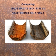
MR0103/ISO 17945 認証 |
石油、石油化学、天然ガス産業 – 腐食性の石油精製環境における硫化物応力割れに耐性のある金属材料 |
| (17) |
ASTM A672 |
中温高圧用電気溶接鋼管の標準仕様 |
| (18) |
ナセSP0742 |
腐食性の石油精製環境における炭素鋼溶接部の使用中の環境割れを防止するための方法と制御 |
| (19) |
API 5L |
ラインパイプ仕様 |
| (20) |
ナセSP0304 |
油田パイプライン用熱可塑性ライナーの設計、設置、運用 |
| (21) |
DNV RP O501 |
配管システムの侵食摩耗 |
材料選択ガイドライン: 表5 – 腐食評価に使用されるパラメータ
| パラメータ |
ユニット |
| デザインライフ |
年 |
| 動作温度範囲 |
°C |
| パイプ径 |
んん |
| 設計圧力 |
MPa |
| 露点温度 |
°C |
| ガス対石油比率(GOR) |
SCF / SBO |
| ガス、石油、水の流量 |
トン/日 |
| CO2含有量と分圧 |
モル % / ppm |
| H2S含有量と分圧 |
モル % / ppm |
| 水分含有量 |
% |
| pH |
該当なし |
| 塩化物含有量 |
ppm |
| 酸素 |
ppm/ppb |
| 硫黄 |
重量% / ppm |
| 水銀 |
重量% / ppm |
| 酢酸濃度 |
ミリグラム/リットル |
| 重炭酸塩濃度 |
ミリグラム/リットル |
| カルシウム濃度 |
ミリグラム/リットル |
| 砂/固形粒子含有量(侵食) |
kg/時 |
| 微生物誘発腐食(MIC)の可能性 |
該当なし |
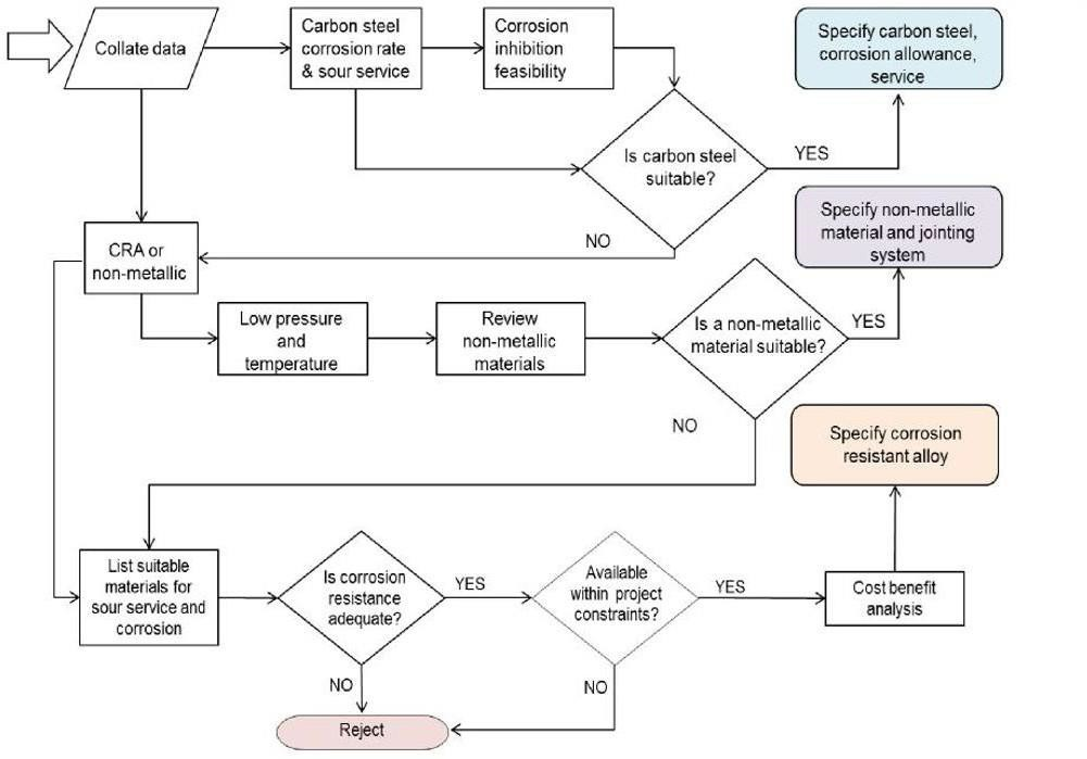
生産システム、処理設備、パイプラインの構築には、可能な限り炭素鋼 (CS) を使用するのが当社の方針です。腐食に対応するために、資産が必要な耐用年数を達成するのに十分な腐食許容値 (CA) が設けられており (セクション 11.2)、可能な場合は、孔食のリスクを減らし、腐食速度を低下させるために腐食抑制剤 (セクション 11.4) が供給されます。
CS の使用が技術的および経済的な選択肢ではない場合、および/または腐食による故障が人員、環境、または会社の資産に許容できるリスクをもたらす場合は、耐腐食合金 (CRA) を使用できます。または、抑制剤処理を施した CS の耐用年数腐食が 6 mm を超える場合は、CRA (ソリッドまたはクラッド CRA) を選択します。CRA を選択する場合は、コスト パフォーマンス基準に基づいて最適な合金を選択する必要があります。図 1 に、CS に代わる材料選択を正当化するプロセスの概要を示す材料選択フロー図を示します。
図1 – 材料選択フロー図
材料選択ガイドライン: 腐食許容量
CS の CA は、最も厳しいプロセス パラメータの組み合わせの下で予測される腐食速度または材料劣化速度に基づいて指定する必要があります。CA の指定は、短期的な材料性能または過渡的条件によって一般的な腐食または局所的な腐食リスクが増大すると予測される場合、腐食速度の比例配分に基づいてアプセット期間を見積もる必要があることに留意して、適切に設計および正当化する必要があります。これらに基づいて、追加の腐食許容値が必要になる場合があります。したがって、CRAS はプロジェクトの初期段階で実行する必要があります。
CA 自体は、確実な腐食制御手段とはみなされません。腐食を検出し、測定し、腐食速度を評価するための時間を提供するための手段とのみみなされます。
プロジェクトの要件と条件に応じて、推定腐食速度が 0.25 mm/年を超える場合、許容 CA を 6 mm 以上に増やすことができます。ただし、これはケースバイケースで検討されます。腐食許容量が過剰である場合は、材料のアップグレードを検討して評価する必要があります。CRA の選択では、コストパフォーマンス基準に基づいて最適な合金が選択されるようにする必要があります。
CA のレベルを指定するには、次のガイドラインを使用します。
- CA は、選択した材料の推定腐食速度に設計寿命(寿命延長の可能性を含む)を乗じて得られた値で、最も近い 3.0、4.5、または 6.0 mm に丸められます。
- CO2 による腐食は、ECE-4 および 5、Predict 6 などの当社承認の腐食モデルを使用して評価できます。
- CA を推定するために使用される腐食速度は、過去のプラント経験と、プロセス条件に関する利用可能な公開データに基づく必要があり、これには以下が含まれます。
- 流体の腐食性、例えば、硫化水素(サワー腐食)、CO2(スイート腐食)、酸素、細菌活動、温度、圧力と組み合わされた水の存在。
- パイプライン内の流動様式を決定する流体の速度。
- 阻害剤による適切な保護を妨げ、細菌の増殖の条件を作り出す可能性のある固形物の堆積。
- パイプ壁が損傷する可能性のある条件
- 圧力部品の CS および低合金鋼は、最小 3.0 mm でなければなりません。特別な場合には、対象品目の設計寿命を考慮し、会社の承認を得て 1.5 mm を指定できます。5 mm の CA を指定できる軽度または非腐食性のサービスの例としては、蒸気、脱気ボイラー給水 (< 10 ppb O2)、処理済み (非腐食性、塩化物制御、無菌) の新鮮な冷却水、乾燥圧縮空気、水を含まない炭化水素、LPG、LNG、乾燥天然ガスなどがあります。ノズルとマンホールのネックには、圧力容器に指定されているものと同じ CA が必要です。
- 最大 CA は 6.0 mm とします。プロジェクトの要件と条件に応じて、推定腐食速度が 0.25 mm/年を超える場合、許容 CA を 6 mm 以上に増やすことができます。ただし、これはケースバイケースで検討されます。腐食許容量が過剰である場合は、材料のアップグレードを検討し、CRA の選択では、コストパフォーマンス基準に基づいて最適な合金が選択されるようにする必要があります。
- 設備のレイアウトとそれが流量に与える影響(デッドレッグを含む)。
- 故障確率、故障モード、および人間の健康、環境、安全性、および物質的資産に対する故障の結果はすべて、材料だけでなく他の分野についてもリスク評価を実施することによって決定されます。
- メンテナンスへのアクセスと
最終的な材料選択については、以下の追加要素を評価に含める必要があります。
- 市場での入手性が良く、溶接性や検査能力などの製造およびサービス性能が文書化されている材料が優先されます。
- 在庫、コスト、互換性、および関連するスペアパーツの入手可能性を考慮して、異なる材料の数を最小限に抑える必要があります。
- 重量に対する強度(オフショア用)
- ピギング/クリーニングの頻度。以下の場合、CA は必要ありません。
- 合金被覆または溶接を施した製品の裏地
- ガスケット面には
- CRAの場合。ただし、侵食性サービスにおけるCRAについては、1mmのCAを指定する必要があります。これは、DNV RP O501 [Ref. (e)(21)](または会社が使用を承認している場合は同様のモデル)による侵食モデリングによって対処およびサポートされる必要があります。
注: 短期的または一時的な条件により、一般的な腐食または局所的な腐食のリスクが増大すると予想される場合は、腐食速度に基づいて腐食継続時間を推定する必要があります。これに基づいて、より高い腐食許容値が必要になる場合があります。さらに、流体速度が高く、浸食腐食が予想される領域では、CRA 配管または CRA 内部被覆/ライニング配管を使用する必要があります。
材料選択ガイドライン: 金属クラッディング
腐食速度が 6 mm CA を超える場合の腐食リスクを軽減するには、CS 母材に CRA クラッディングまたは溶接オーバーレイ材料の層を指定するのが適切です。疑問がある場合は、材料の指定者は会社にアドバイスを求める必要があります。容器の CRA クラッディングが指定されている場合、または CRA クラッディングが爆発溶接接合、金属ロール接合、または溶接オーバーレイによって適用される場合は、SSC 耐性品質のベース プレートが必要ですが、HIC 耐性ベース プレートは必要ありません。
爆発接合またはロール接合を選択した場合は、母材の 100% 全体で最小厚さ 3 mm を達成する必要があります。オーバーレイを選択した場合は、最低 2 パスが必要であり、最小厚さ 3 mm を達成する必要があります。溶接性に問題がある場合は、爆発接合を検討できます。
一般的な外装材には以下のものがあります。
- 316SS(塩化物孔食のリスクが高い場合は、タイプ317SSを指定できます)。
- 合金904;
- 合金825(溶接によりクラッド板の耐食性が劣る可能性があるため、ロール接合に限定)
- 合金
容器の厚さが比較的薄い場合(最大 20 mm)、ライフサイクル コスト分析を使用して、固体 CRA 材料の選択がより商業的に実行可能かどうかを判断する必要があります。これはケースバイケースで検討されます。
クラッド パイプまたはライニング パイプは、腐食性の高い流体を輸送するフローラインに使用できます。API 5LD の要件が適用されます。経済的な理由から、これらのパイプラインは中程度の直径と短い長さになります。クラッド パイプは、内面に 3 mm の CRA 層が結合された鋼板から形成されます。CRA クラッドは、冶金結合、共押し出し、または溶接オーバーレイのいずれかで形成できます。また、海底用途では、減圧リスクが低い場合はプロセス/機械結合を使用できます。溶接パイプ仕様の場合、CRA クラッド パイプはパイプに形成され、継ぎ目は CRA 消耗品で溶接されます。
請負業者は、CS 上の合金クラッドまたは溶接オーバーレイに関する既存の会社固有の仕様に基づいて、圧力容器および熱交換器に適用されたライニングおよび一体型クラッディングの設計、製造、検査の要件を網羅する別の仕様を発行するものとします。ASTM 仕様 A263、A264、A265、A578、および E164、および NACE MR0175/ISO 15156 を参照として使用できます。
材料選択ガイドライン: 腐食防止剤の適用
腐食抑制剤の選択と評価は、当社の手順に従うものとします。設計上、ガス凝縮液には 95% の腐食抑制効率、石油には 90% を想定するものとします。また、設計中は抑制剤の可用性は 90% の可用性に基づいて決定し、運用段階では抑制剤の最小可用性は 90% を超えるものとします。抑制剤の可用性は、FEED 段階でプロジェクトごとに指定するものとします。ただし、腐食抑制剤の使用は、NACE MR0175/ISO 15156 の酸性サービス材料選択要件の代替として機能してはなりません。
抑制システムの有効性を動作中に検証できるようにするには、設計に次の内容を含める必要があります。
- 最も腐食の可能性が高い場所
- 腐食速度の高い箇所へのアクセス性、壁厚測定時の
- 固形物/破片のサンプルを採取する能力
- 腐食測定装置を使用して、抑制効果を監視する必要があります。
- 鉄のカウントを可能にする施設は、阻害物質のモニタリングの設計に含める必要があります。
設計においては、禁止されたシステムについて以下の主要業績評価指標 (KPI) を測定し、傾向を把握できるようにする必要があります。
- 抑制システムが機能しない時間数
- 実際の注入濃度と目標注入濃度の比較
- 阻害剤残留濃度と目標濃度の比較
- 目標抑制腐食と比較した平均腐食速度
- 腐食速度または溶解鉄濃度の変化は、
- 腐食監視が利用できない
材料選択ガイドライン: サワーサービス用材料
H2S 含有環境で使用する配管および機器の材料選択は、最新の COMPANY 酸性環境用材料仕様に準拠し、上流プロセスについては NACE MR0175/ISO15156、下流プロセスについては NACE MR0103/ISO 17945 に従って検証される必要があります。
316L SS は、高温が 60 °C を超え、流体の H2S および塩化物含有量が高い場合を除き、ほとんどの酸性サービスで考慮されますが、これはケースバイケースで考慮されます。これらの制限を超える動作条件では、NACE MR0175/ISO15156 に準拠した高合金材料が考慮される場合があります。さらに、塩化物含有量の持ち越しが削減される蒸気分離を考慮する必要があります。
ISO 15156 パート 3 の表 A2 の環境および材料制限に従う場合、容器に 316L SS クラッドを検討できます。316L クラッドの容器は、酸素にさらされるとクラッドの塩化物応力割れの危険があるため、開ける前に 60 °C 以下に冷却する必要があります。これらの制限外の動作条件の場合、NACE MR0175/ISO15156 に準拠した高合金材料を検討できます。クラッドは、ノズルやその他の付属品を含む表面全体の 100% にわたって連続していることを確認するために検査する必要があります。
サワーサービス配管用の鋼は、HIC 耐性があり、硫黄含有量が 0.01% 未満で、介在物の形状を制御するためにカルシウムで二次処理されている必要があります。縦方向溶接パイプ用の鋼は、硫黄含有量が 0.003% 未満で、介在物の形状を制御するためにカルシウムで二次処理されている必要があります。
酸性サービス環境でのボルト締めに関する具体的なガイドラインについては、このガイドラインのボルト締めセクション (セクション 12.8) を参照してください。
購入者が酸性サービス要件を指定する場合、以下が適用されます。
- すべての材料には、溶解および熱処理までの完全なトレーサビリティを確保するためのマークが付けられる。
- 熱処理 焼戻し条件の場合、焼戻し温度を明記する。
- 補足接尾辞「S」は、HIC 試験および UT 検査を除く酸性サービスに関する追加の補足要件に加えて、MDS に従って納品された材料を指定するために使用されます。
- 補足接尾辞「SH」は、サワーサービスとHICテストおよびUTに関する追加の補足要件を含むMDSに従って納品された材料を指定するために使用されます。
- 材料製造業者は、ISO 9001 または購入者が承認した他の品質要求規格に従って認証された品質システムを備えていなければなりません。
- 検査文書は ISO 10474 /EN 10204 タイプ 1 に従って発行され、この仕様への準拠を確認するものとします。
- 完全に殺菌された材料は
- 酸性サービス パイプの場合、材料は API 5L 付録 H – PSL2 の要件に準拠する必要があります。厳しい酸性サービスの場合、低強度の標準化グレードが指定され、X65 グレードまでに制限されます。
- 耐酸性試験はベース材料と溶接部の両方に必要であり、SSC および HIC の定期試験は NACE TM0177 および NACE TM0284 に準拠する必要があります。SOHIC および軟質部割れの試験では、実際の製造溶接を使用して生成された溶接部によるフルリング試験が必要になる場合があります。4 点曲げ試験は NACE TM0316 に従って実行する必要があります。
- 硬度は上流についてはISO 15156、下流についてはNACE MR0173/NACE SP0742に準拠
材料選択ガイドライン: 具体的な考慮事項
次のリストには、特定のシステムに固有のものではなく、すべての COMPANY プロジェクトに適用される特定の材料選択の考慮事項が含まれています。
- 請負業者は、ライセンサー I がパッケージ機器内で行った材料の選択について全責任を負うものとします。請負業者は、この仕様に沿って MSD、材料選択の原則、CRAS、RBI、MCA を含むすべての情報を提供し、会社の承認を得るものとします。材料の変更はすべて、請負業者の保証のもとで行われます。
- 脆性破壊の可能性を防ぐために、パイプ材料の破壊靭性特性に注意を払う必要があります。
- アルミニウム青銅材料は、溶接性が悪く、メンテナンスに問題があるため、溶接部品には使用しないでください。
- 無電解ニッケルメッキ(ENP)は、以下の承認がない限り使用してはならない。
- 潤滑油およびシールオイルシステムの材質は、適合性が認められる場合はSS316Lとする。
- 表面コンデンサーおよびその他の交換器の水ボックス内のゴムライニングは、会社の承認なしに使用してはなりません。
- 低圧の石油・ガス、水、油、雨水、排水用の GRE/HDPE 素材は、メーカーの許容サービス パラメータおよび負荷 (埋設時) 制限内での使用が当社の承認を得て許可されています。
- 熱交換器の設計は、プロセス要件に基づいて行う必要があります。したがって、材料の選択はすべての熱交換器に対してカスタマイズされており、標準化することはできませんし、標準化すべきでもありません。
- ステンレス鋼 304、304L は、UAE の湿気の多い雰囲気に適さない外部材料用途には使用できません。
FBEコーティングパイプライン
材料選択ガイドライン: 特定の用途とシステム
このセクションでは、上流(陸上と海上)および下流(製油所)資産を含む当社の施設の範囲内に存在する特定のシステムに関する重要なガイドラインを示します。概要
これらの施設内にあるユニットの材質オプション、潜在的な損傷メカニズム、およびそのようなメカニズムの緩和策を次の表に示します。各ユニットの詳細については、このセクションの残りの部分で説明します。記載されている腐食メカニズムの詳細については、API RP 571 を参照してください。
注: このセクションに記載されている材料オプションは、ガイドラインとしてのみ考慮されます。請負業者は、セクション 10 で指定された成果物を通じて、プロジェクトの各フェーズを通じてプロジェクト固有の材料を選択する責任を負うものとします。
材料選択ガイドライン: 表6 – 上流プロセス機器および配管の材料推奨事項
| サービス |
素材オプション |
損傷メカニズム |
緩和 |
| 坑口固定スプール/ジャンパーおよびマニホールド |
CS+CRA クラッディング、CRA、CS+CA |
CO2 腐食、湿潤 H2S 損傷、塩化物応力腐食割れ (CSCC) |
材料の選択。
(このような場所では腐食防止が効果的でないと判断される場合/腐食性の高いサービス/CRAクラッドオプションが推奨されます)
酸っぱいサービスのためのデザイン。
UNS N06625/UNS N08825 クラッド オプション。
酸性サービスには、NACE MR0175/ISO 15156 酸性サービス要件が適用されます。 |
| パイプライン/フローライン |
CS+CA |
水素脆化、CO2腐食、湿潤H2S損傷、CSCC、MIC |
埋設金属部分を保護するための陰極保護およびコーティング。
殺生物性腐食防止剤およびピグ/スクラッパーの使用。
定期的なインライン検査(インテリジェントピギング)により壁の厚さを測定し、適切な洗浄ピグを使用して定期的に洗浄します。 |
| 湿性炭化水素ガス |
CS+CA
(+CA/CRAクラッディング)、316SS、DSS、SDSS |
CO2腐食、湿潤H2S損傷、CSCC、塩化物孔食、 |
材料の選択
酸っぱいサービスのためのデザイン
TOL 腐食を評価し、腐食余裕が 6 mm を超える場合は CRA クラッドを指定して腐食を軽減する必要があります。
腐食防止剤の使用 酸性サービスには、NACE MR0175 /ISO 15156 酸性サービス要件が適用されます。
入口での選択は主に酸性サービス要件に基づいて行われます |
| 乾燥炭化水素ガス |
CS+CA(+CRAクラッディング)、316SS |
CO2腐食、湿ったH2Sによる損傷。 |
材料の選択
指定された条件範囲内で動作していることを確認する
腐食監視は、ガスが乾燥状態を保つために不可欠です。湿気のある期間が予想される場合は、CA が必要になることがあります。 |
| 安定化凝縮液 |
CS+CA |
CO2腐食、湿潤H2S損傷、MIC |
材料の選択
細菌活動のモニタリング |
| 生産水 |
CS+CA、316SS、DSS、SDSS。CS+CRA ライナー、CS+CRA (冶金結合) |
CO2 腐食、湿潤 H2S 損傷、CSCC、MIC、O2 腐食 |
材料の選択
酸素の侵入を防ぐ設計
殺生物剤、酸素除去剤、腐食防止剤の使用
容器にはCS+内張りが選択できます。
パイプ材料の仕様は、プロセス/流体の条件に大きく依存します。
酸性サービスには、NACE MR0175 /ISO 15156 酸性サービス要件が適用されます。 |
| 石油・ガス輸出 輸出・原料ガス |
CS+CA |
CO2腐食、湿潤H2S損傷、MIC |
材料の選択
ガス輸出用露点温度監視
ガス輸出が「湿式」であると考えられる場合、腐食評価結果に基づいて CRA (クラッド/固体) 材料へのアップグレードが必要になる場合があります。 |
| ガス脱水(TEG) |
CS+CA、316SS、CS+CRA |
蒸留塔オーバーヘッドにおける酸凝縮による腐食 |
材料の選択はライセンサー主導ですが、責任は請負業者にあります。 |
| 注入化学薬品(腐食防止剤など) |
CS(+CA)、316SS、C-PVC |
化学的適合性、腐食。 |
材料の選択は、化学的適合性の観点からベンダー/サプライヤーと協議する必要があります。 |
| 水銀除去 |
CS+CA |
CO2腐食、湿潤H2S損傷、CSCC、塩化物孔食
*液体金属脆化 |
材料の選択
*アルミニウムまたは銅含有チタン合金は、液体水銀の危険がある場所では使用しないでください。 |
| アミン |
CS+CA/CRAクラッド、316SS |
CO2 腐食、湿潤 H2S 損傷、アミン応力腐食割れ (ASCC)、アミン腐食、浸食 (耐熱塩による) |
設計されたシステムに適した動作速度、温度、およびアミン塩をチェックするための定期的なサンプリング。
リッチアミンは316SSとなります。
容器の内部は 316SS でなければなりません。速度制限。
設計温度が 53°C を超える場合、ASCC を防止するために CS に PWHT を指定する必要があります。使用する PWHT 温度は API RP945 に準拠する必要があります。 |
| フレア |
CS+CA、316SS
*310SS、308SS、合金800、合金625 |
低温破壊、大気腐食、クリープ破壊(熱疲労)、
CSCC。 |
CS +ライニングはフレアドラムのオプションです
最小設計温度と最大設計温度の両方を考慮した設計
低温脆性破壊の問題に対処する必要があります。
海洋環境では内部腐食のメカニズムが発生する可能性が高くなります。
* フレアチップの材料。 |
| PLR(PIGランチャーレシーバー) |
シーリング面用CS+溶接オーバーレイ |
CO2腐食、湿潤H2S損傷、堆積物下腐食、MIC、
デッドレッグ腐食 |
材料選定 定期検査
殺生物剤および腐食防止剤の使用。 |
表7 – 下流プロセス機器および配管の材料に関する推奨事項
| サービス |
素材オプション |
損傷メカニズム |
緩和 |
| 原油ユニット |
CS、5Cr-1/2 Mo、9Cr-1Mo、12Cr、317L、904L、またはMo含有量の高いその他の合金(NACを避けるため)、CS+SSクラッド |
硫黄腐食、硫化、ナフテン酸腐食(NAC)、湿潤H2S損傷、HCL腐食 |
材料の選択 脱塩
流速限界。
腐食防止剤の使用 |
| 流動接触分解 |
CS + CA、1Cr-1/2Mo、2-1/4Cr-1Mo、5Crおよび9Cr鋼、12Cr SS、300シリーズSS、405/410SS、合金625
内部浸食/断熱耐火ライニング |
触媒の侵食
高温硫化、高温浸炭、クリープ、クリープ脆化、ポリチオン酸応力腐食割れ。高温黒鉛化、高温酸化。
885°F 脆化。 |
材料の選択 耐侵食性ライニング
触媒の乱流と触媒のキャリーオーバーを最小に設計する |
| FCC ライトエンドリカバリ |
CS + CA (+ 405/410SS クラッド)、DSS、合金 C276、合金 825 |
水性H2S、アンモニア、シアン化水素(HCN)の組み合わせによって引き起こされる腐食。
湿潤H2S損傷-SSC、SOHIC、HICアンモニウム応力腐食割れ、炭酸塩応力腐食割れ |
材料の選択
洗浄水にポリサルファイドを注入して HCN 含有量を低下させます。
速度制限
腐食防止剤注入。酸素侵入防止 |
硫酸
アルキル化 |
CS + CA、低合金鋼、合金20、316SS、C-276 |
硫酸腐食、水素溝、酸希釈、汚れ、CUI。 |
材料の選択 – ただし、高合金は一般的ではない
速度制御(CS- 0.6m/s~0.9m/s、316Lは1.2m/秒に制限)
NACE SP0294準拠の酸タンク
防汚注入 |
| 水素処理 |
CS、1Cr-1/2Mo、2-1/4Cr-1Mo、18Cr-8Ni SS、316SS、321、347SS、405/410SS、合金20、合金800/825、モネル400 |
高温水素侵食 (HTHA)、水素-H2S 混合物による硫化、湿潤 H2S 損傷、CSCC、ナフテン酸腐食、硫化アンモニウム腐食。 |
API 941-HTHA に準拠した材料選択。
速度制御(流体の分布を維持するのに十分な高さ)
ASME VIII / B31.3に準拠したPWHT |
| 触媒改質 |
1-1/4Cr-0.5Mo、2-1/4Cr-0.5Mo、 |
クリープ割れ、HTHA、SSC-アンモニア、SSC-塩化物、水素脆化、塩化アンモニウム腐食、クリープ破断 |
API 941-HTHAに準拠した材料選択。硬度制御、PWHT |
| 遅延コーカー |
1-1/4Cr-.0.5Mo 410S または 405SS、5Cr-Mo または 9Cr-Mo 鋼、316L、317L で被覆 |
高温硫黄腐食、ナフテン酸腐食、高温酸化/浸炭/硫化、エロージョン腐食、水性腐食(HIC、SOHIC、SSC、塩化アンモニウム/亜硫酸水素塩、CSCC)、CUI、熱疲労(熱サイクル) |
応力発生源を最小限に抑え、微粒子の Cr-Mo 鋼で、靭性が優れています。 |
| アミン |
CS + CA /
CS+ 316Lクラッド、316SS |
CO2 腐食、湿潤 H2S 損傷、アミン応力腐食割れ (ASCC)、高アミン腐食、浸食 (耐熱塩による) |
表6のアミンを参照してください。 |
硫黄回収
(ライセンスユニット) |
CS、310SS、321SS、347SS、 |
炭素鋼の硫化、湿潤H2S損傷/亀裂、(SSC、HIC、SOHIC)、弱酸腐食、 |
CS の深刻な腐食を回避するために、配管を露点温度以上で操作します。
割れを防ぐための溶接部のPWHT硬度制御
HIC耐性鋼。 |
パイプライン
パイプラインの材質は、既存の会社固有のパイプラインの材質仕様に準拠します。炭素鋼 + 腐食許容量がデフォルトの材質となります。腐食許容量は、設計寿命をはるかに超えた運用を考慮して可能な限り高くする必要があり、各プロジェクトごとに個別に決定されます。パイプラインのコーティングは、AGES-SP-07-002、外部パイプラインコーティング仕様で指定されます。
凝縮水のある炭化水素パイプライン システムでは腐食防止剤の使用が推奨されており、海底パイプラインのデフォルト オプションとなります。つまり、CS + CA + 腐食防止剤です。ピギング、CP などの追加の腐食管理技術も検討する必要があります。腐食防止剤の選択と評価は、会社の手順に従って行う必要があります。
パイプラインの CRA オプションの選択は、ライフサイクルコスト分析によって徹底的に評価する必要があります。化学物質のコストと腐食管理技術、化学物質の輸送と取り扱いのロジスティクスに関する HSE の考慮事項はすべて、検査要件と同様に分析に組み込まれる必要があります。
炭化水素配管
プロセス配管の材料選択は、第 11 条の要件に従って請負業者が行うものとします。サービスごとの材料ガイドラインは、上流施設と下流施設の両方について、それぞれ前述の表 6 と 7 に示されています。すべての溶接と合格基準は、ASME B31.3 の要件に従って実施する必要があります。配管材料は、ADNOC 配管材料仕様 AGES-SP-09-002 に準拠して配管によって指定されるものとします。
デッドレッグには特別な個別の材料選択が必要になる場合がありますが、流れが停滞する領域での腐食制御には CRA または CRA クラッディングが必要になる場合があります。ただし、配管設計では、腐食の可能性と重大性を軽減するためにデッドレッグを回避することを考慮する必要があります。デッドレッグが回避できない場合は、内部コーティング、抑制剤と殺生物剤の投与、定期的な腐食監視が推奨されます。これは、静的機器にも適用されます。
設計時には、特に配管部門では、亜鉛の脆化を避けるために、SS が亜鉛メッキ部品に接触しないように注意する必要があります。これは、溶接作業など、亜鉛が拡散する温度では懸念事項となります。
ユーティリティシステム
材料選択ガイドライン: 表8 – ユーティリティサービスの材料選択ガイドライン
| サービス |
素材オプション |
損傷メカニズム |
緩和 |
| 燃料ガス |
CS、316SS |
燃料ガスが湿っている場合:CO2腐食、塩化物孔食、CSCC、湿ったH2S損傷 |
材料の選択
代替燃料ガスが使用される可能性がある起動時の制御された動作条件。 |
| 不活性ガス |
CS + 最小CA |
燃料ガス製品からの一般的な汚染物質 |
材料の選択 (腐食レベルは、排気ガスからの燃料ガスなど、使用される不活性ガスによって異なります。) |
| ディーゼル燃料 |
CS + CA、316SS、CS + CA+ライニング
*鋳鉄 |
汚染物質のリスク |
CS +ライニングはタンクに適しています
*ポンプは鋳鉄製とします。 |
| 計器/プラントエア |
亜鉛メッキCS、316SS |
大気腐食 |
制御された濾過 |
| 窒素 |
亜鉛メッキCS、316SS |
なし。腐食はブランケット作業中の酸素の侵入により発生する可能性があります。 |
侵入の可能性が高い場合や清潔さが求められる場合には、仕様をアップグレードします |
| 次亜塩素酸塩 |
CS + PTFEライニング、C-PVC、C-276、Ti |
すきま腐食、酸化 |
材料の選択
投与/温度制御 |
| 下水 |
316 SS、GRP |
塩化物孔食、CSCC、CO2腐食、O2腐食、MIC |
材料の選択 |
| 淡水 |
エポキシコーティングCS、CuNi、銅、非金属 |
O2腐食、MIC |
飲料水に使用しない場合は清浄度の監視/殺生物剤の使用 |
| 冷却水 |
CS + CA、非金属 |
冷却水の腐食 |
O2除去剤と腐食防止剤の使用
CS コンポーネントと接触するグリコールと水の混合冷却システムは腐食を引き起こすことが知られています。グリコールは腐食防止剤と混合する必要があります。 |
| 海水 |
CS + ライニング、SDSS、合金 625、Ti、CuNi、GRP |
塩化物孔食、CSCC、O2腐食、隙間腐食、MIC |
材料の選択
温度制御 |
| 脱塩水 |
エポキシコーティングCS、316SS、非金属 |
O2腐食 |
材料の選択 |
| 飲料水 |
非金属(例:C-PVC/HDPE)、Cu、CuNi、316 SS |
MIC |
犠牲陽極は飲料水システムでは使用しないでください。 |
| ファイアーウォーター |
CuNi、CS+3mmCA(最小)+内部コーティング、GRVE、GRE、HDPE |
塩化物孔食、CSCC、O2腐食、隙間腐食、MIC |
腐食メカニズムは消火水の媒体に依存します。
非金属オプションでは火災の危険性を考慮する必要がある |
| 開いた排水溝 |
非金属
CS + エポキシライニング |
塩化物孔食、CSCC、O2腐食、隙間腐食、MIC、大気腐食 |
被覆容器からの配管はCRAとする。 |
| 閉鎖排水溝 |
CS + CA、316SS、DSS、SDSS、CS +CRAクラッド |
CO2 腐食 湿潤 H2S 損傷、CSCC、隙間腐食、O2 腐食、ASCC、MIC |
材料の選択 |
燃料ガスは、輸出ガスのように脱水カラムの下流から乾燥ガスとして供給されるか、または完全に乾燥されておらず、配送配管内での水分の凝縮を防ぐために加熱される可能性のある分離された低圧ガスとして供給されます。
乾燥ガスは、公称 CA 1 mm の CS パイプで輸送され、抑制されません。減圧温度を分析し、-29 °C 未満の場合は、低温 CS を指定する必要があります。乾燥していない燃料ガスは、生成された湿ったガス (露点より 10 °C 未満) と同様に処理する必要があります。清浄度が必要な場合は、316 SS を指定する必要があります。
非腐食性と見なされます。表 8 を参照してください。
非腐食性と考えられ、CS は適していますが、ディーゼルの品質によっては、多少の汚染物質が含まれる場合があります。このような場合、3 mm CA の CS で製造されたディーゼル貯蔵タンクは、腐食や、機器に影響を及ぼす可能性のあるディーゼルへの腐食生成物の沈殿を防ぐために、内部コーティングする必要があります。上部表面の結露によっても腐食生成物が発生する可能性があるため、タンク全体をコーティングする必要があります。代替案としては、GRP などの非金属で製造されたタンクを使用することです。
亜鉛メッキ CS は、非腐食性にもかかわらず、大口径配管用の高品質空気および窒素システムによく使用され、小口径配管には 316 SS が使用されます。水分の浸入の可能性がある場所、またはフィルターの下流で清浄度が求められる場所では、316 SS の代替オプションを全面的に検討する必要があります。DSS コネクタと継手を使用する必要があります。
処理されている場合(セクション 11.2 で定義)、CA 付きの CS は許容されます。処理されていない場合、淡水システムは適切な CRA または CRA クラッディング付きの CS にアップグレードする必要があります。
飲料水は、衛生基準に適合するコーティングで内部がコーティングされた CS タンク、または GRP で作られたタンクに保管する必要があります。GRP タンクを使用する場合は、タンクへの光の侵入と保管水中の藻類の繁殖を防ぐために、タンクの外部をコーティングする必要があります。外部コーティングの劣化を防ぐには、UV 耐性グレードを指定する必要があります。配管は非金属材料で、適切な直径の場合は従来の銅配管を使用する必要があります。または、清潔さの理由から 316 SS を指定することもできます。
海水システムの材料選択は温度に大きく依存するため、ISO 21457 を参照して選択する必要があります。推奨材料は表 8 に示されています。内部ライニング付きの CS は、API 15LE および NACE SP0304 に従って脱気海水システムにのみ選択する必要があります。
海水を媒体として使用する消火水システムについては、セクション12.3.8を参照してください。
脱塩水は CS に対して腐食性があるため、これらのシステムは 316 SS でなければなりません。材料メーカーからの入力と会社からの承認があれば、非金属を選択することもできます。タンクは CA と適切な内部ライニングを備えた CS にすることができます。
海水を媒体とするほとんどの恒久的に湿潤する消火水システムの場合、推奨材料は 90/10 CuNi またはチタンです (ISO 21457 のユーティリティ表 8 を参照)。
消火水システムには、空気を含んだ真水が含まれ、輸送されます。地上の主管は 90/10CuNi で構築でき、地下の主管はコーティングや陰極保護を必要としない GRVE (ガラス強化ビニルエステル) で構築できます。大型バルブは、内部の濡れ面と CRA トリムに CRA クラッドを施した CS にする必要があります。重要なバルブは、完全に CRA 材料で製造する必要があります。ガルバニック腐食の問題を回避するために、異種材料間の電気的絶縁が必要な場合は、必ず絶縁スプールを指定する必要があります。
NiAl ブロンズ バルブは 90/10CuNi 配管と互換性がありますが、NiAl ブロンズと CuNi は硫化物汚染水には適していません。
材料の選択は水質と水温によって異なります。設計では黒体温度を考慮する必要があります。
消火水システム用の内部エポキシコーティング炭素鋼配管は、会社の承認が必要です。
オープン ドレン設備の材質は、内部ライニング付きの CS を選択する必要があります。配管については、会社の承認待ちの適切な非金属が推奨されます。サービスの重要度が低い場合は、代わりに 6 mm CA 付きの CS を指定することもできます。オープン ドレン タンクは、適格な有機コーティング システムで内部ライニングし、陰極保護システムで補完する必要があります。
密閉式排水管の材料選択では、システム内の潜在的な炭化水素の状態を考慮する必要があります。密閉式排水管に酸性炭化水素が流入する場合は、酸性サービスの要件 (セクション 11.5 による) が適用されます。すべてのドラムとタンクのブランケット システムの設計では、残留酸素の可能性を考慮する必要があり、材料選択の際に考慮する必要があります。
バルブ
バルブの材質選択は、バルブが分類される配管クラスに適したもので、ASME B16.34 の要件に準拠している必要があります。バルブ材質の詳細については、配管およびパイプライン バルブ仕様書 AGES-SP-09-003 を参照してください。
海中用途のバルブは、API 6DSS に従って選択されます。バルブは、ADNOC 仕様 AGES-SP-09-003 に準拠して選択する必要があります。
静的機器
圧力容器の材料ガイドラインは、上記の表 6 および 7 に示されています。これは通常、内部ライニング付きの CS または CRA クラッディングです。クラッディング付きの CS とソリッド CRA オプションの選択に関するガイドラインは、セクション 11.3 に記載されていますが、ケースバイケースで検討する必要があります。溶接および受け入れ要件は、ASME IX に準拠する必要があります。
容器に酸性サービス材料の選択が適用される場合は、セクション 11.5 を参照してください。316 SS の NACE MR0175 / ISO 15156-3 制限外の場合、容器は内部を合金 625 で被覆/溶接オーバーレイする必要があります。
セクション 11.6 で述べたように、熱交換器の設計、つまり材料の選択は、その使用要件によって異なります。ただし、すべての場合において、材料は次のガイドラインに従う必要があります。
- 設計寿命要件を満たすために選択される材料は、
- 材料の選択は設計に基づいて行われる
- チタン ASTM B265 グレード 2 は、海水と高濃度グリコールを含む熱交換器用途に推奨されるグレードです。すべてのチタン熱交換器の設計では、チタンの水素化の可能性を考慮し、条件が 80 °C を超えないこと、pH が 3 未満または 12 以上 (H2S 含有量が多い場合は 7 以上) であること、およびガルバニック結合などの水素を生成するメカニズムがないことを確認する必要があります。
- CA は一般に熱交換器の CS には使用できないため、適切な CRA への仕様のアップグレードが必要になる場合があります。
- シェルアンドチューブ設計でチューブに CuNi を使用する場合は、表 9 の最小速度と最大速度を遵守する必要があります。ただし、これらの値はパイプの直径によって変化するため、ケースバイケースで設計する必要があります。
材料選択ガイドライン: 表9 – CuNi熱交換器チューブの最大および最小流速
| チューブ材質 |
速度(m/s) |
| 最大 |
最小 |
| 90/10 銅ニッケル |
2.4 |
0.9 |
| 70/30 銅ニッケル |
3.0 |
1.5 |
設計の詳細については、AGES-SP-06-003、シェルアンドチューブ熱交換器仕様を参照してください。回転装置/ポンプ
ポンプの材質クラスの選択は、AGES-SP-05-001 遠心ポンプ (API 610) 仕様を使用する会社のプロジェクトごとに請負業者が個別に行うものとします。以下の表 10 に、システムごとのポンプの材質クラスの選択に関するガイドラインを示します。特定の動作条件で仕様のアップグレードが必要な場合など、材質の詳細については、AGES-SP-05-001 を参照してください。
材料選択ガイドライン: 表10 – ポンプの材料分類
| サービス |
材質クラス |
| 酸性炭化水素 |
S-5、A-8 |
| 非腐食性炭化水素 |
S-4 |
| 腐食性炭化水素 |
A-8 |
| 凝縮液、非通気 |
S-5 |
| 凝縮液、空気混入 |
C-6、A-8 |
| プロパン、ブタン、液化石油ガス、アンモニア、エチレン、低温サービス |
S-1、A-8 |
| ディーゼル油、ガソリン、ナフサ、灯油、ガス油、軽質・中質・重質潤滑油、燃料油、残渣、原油、アスファルト、合成原油残渣 |
S-1、S-6、C-6 |
| キシレン、トルエン、アセトン、ベンゼン、フルフラール、MEK、クメン |
S-1 |
| 硫黄化合物を含む石油製品 |
C-6、A-8 |
| 腐食性の水性相を含む石油製品 |
A-8 |
| 液体硫黄 |
S-1 |
| 液体二酸化硫黄、乾燥(最大0.3%重量H2O)、炭化水素の有無にかかわらず |
S-5 |
| 二酸化硫黄水溶液、全濃度 |
A-8 |
| スルホラン(シェル独自の化学溶剤) |
S-5 |
| ナフテン酸を含む短い残留物(酸価0.5 mg KOH/g以上) |
C-6、A-8 |
| 炭酸ナトリウム |
I-1 |
| 水酸化ナトリウム、濃度<20% |
S-1 |
| グリコール |
ライセンサーによって指定 |
| DEA、MEA、MDEA、TEA、ADIP、またはスルフィノール溶液(H2SまたはCO2のいずれかを含む)(1% H2S以上) |
S-5 |
| DEA、MEA、MDEA、TEA、ADIP、またはスルフィノール溶液、脂肪、CO2を含み、1% H2S未満または120°C以上 |
A-8 |
| 水の沸騰と処理 |
C-6、S-5、S-6 |
| ボイラー給水 |
C-6、S-6 |
| 汚水と還流ドラム水 |
C-6、S-6 |
| 汽水 |
A-8、D-2 |
| 海水 |
ケースバイケース |
| 酸っぱい水 |
D-1 |
| 淡水、エアレーション |
C-6 |
| 水を排水する。弱酸性、非通気 |
A-8 |
計器用チューブおよび継手
一般的に、計装用には1フィート未満の小径チューブが使用される。 私 化学物質 私 潤滑油/シールオイルシステムは、別途指定がない限り、904L 材料で作られるものとします。
陸上施設の酸性サービス要件のないユーティリティサービス(計器用空気、油圧流体、潤滑油、シール油など)の計器用配管/継手は、316L SS でなければなりません。
酸性サービスを伴うプロセスガス媒体の場合、計器配管用の CRA 材料 (316L/6Mo/インコネル 825) の適用は、塩化物、H2S 分圧、pH、および設計温度を考慮した NACE MR0175/ISO 15156-3 の材料制限に準拠して選択するか、精製環境で使用される計器配管の場合は NACE MR0103/ISO 17495 に準拠して選択する必要があります。
計器配管材料の選択では、特に塩化物を含む環境では、外部塩化物誘発応力腐食割れのリスクと外部孔食および隙間腐食のリスクも考慮する必要があります。したがって、オフショア施設の計器配管(サービスに関係なく)では、露出した海洋環境に対して、ケースバイケースで PVC コーティング(厚さ 2 mm)316 SS チューブを検討する必要があります。または、6Mo オーステナイト SS は海洋環境で 120 °C まで適切であると見なされており、その使用はケースバイケースで決定されます。
ボルト締め
すべてのボルトとナットは、最低でも EN 10204 タイプ 3.1 に準拠した認証を付与され、低温サービスの場合はタイプ 3.2 に準拠した認証を付与されて供給されるものとします。
ボルト材料は、付録1「金属材料選定基準」に記載されている鉄金属、非合金および合金のボルト表に準拠する必要があります。定義された温度範囲に適したボルトは、以下の表11に記載されています。
材料選択ガイドライン: 表11 – ボルト締め付け温度範囲の材料仕様
| 温度範囲(°C) |
材料仕様 |
サイズの制約 |
| ボルト |
ナッツ |
| -100 から +400 |
A320 グレード L7 |
A194 グレード4/S3またはグレード7/S3 |
≤ 65 |
| A320 グレード L43 |
A194 グレード 7/S3 または A194 グレード 4/S3 |
< 100 |
| -46 から + 4004 |
A193 グレード B7 |
A194 グレード 2H |
全て |
| -29 から + 5404 |
A193 グレード B161 |
A194 7年生 |
全て |
| -196/+ 540 |
A193グレードB8M2 |
A194 グレード M/8MA3 |
全て |
ノート:
- このグレードは、恒久的に浸漬される機器には使用しないでください。グレード B16 は、グレード B7 の温度範囲外の高温環境での使用を目的としています。
- タイプ316のボルトとナットは、湿った塩水にさらされる場合、60°Cを超える温度で使用しないでください。
- クラス1で8MAを使用する
- 温度下限は解釈の対象となり、それぞれ明確にする必要がある。
CS および/または低合金ボルト材料は、ASTM A153 に準拠した溶融亜鉛メッキ、または同様の信頼性の高い腐食保護が施されている必要があります。LNG サービスでは、SS が亜鉛メッキされたアイテムに接触する可能性に十分注意する必要があります。
厚い亜鉛層の溶解によりボルトの張力が失われる可能性がある用途では、リン酸塩処理を使用する必要があります。ポリテトラフルオロエチレン (PTFE) でコーティングされたボルト (Takecoat & Xylan など) または同等品を使用できますが、これらのボルトが陰極保護に依存している場合は、測定によって電気的導通が検証されている場合にのみ使用する必要があります。カドミウムメッキされたボルトは使用しないでください。
外部のボルト、ナット、スペーサーを非金属コーティングで保護する必要がある場合は、ISO 17025 認定の第三者研究所で実施される 6,000 時間の塩水噴霧テストに合格した PTFE コーティングでコーティングする必要があります。サンプルは、塗料メーカーからではなく、塗布施設から採取する必要があります。
潜在的な非金属コーティングのためのボルト締めは以下に適用されます。
- 使用温度が 200 °C 未満の絶縁フランジボルトを含む、すべての外部フランジ接続 (工場および現場で組み立て)。
- 定期的なメンテナンスや検査のために取り外す必要がある機器のボルト。ボルトの非金属コーティングは、次の場合には適用されません。
- すべての構造ボルト;
- サプライヤーのパッケージまたは製造業者の標準機器、さまざまな標準値のアセンブリ、および計装内のさまざまなコンポーネントの組み立てに使用されるファスナー/ボルト。請負業者は、サプライヤー/製造業者の標準コーティングの適合性をケースバイケースで確認するものとします。
- 合金ファスナー;
- バルブ用ボンネットボルトおよびグランドボルト。
- ストレーナーのブローオフ接続用のボルト。
- メーカー標準の配管特殊品(サイトグラス、レベルゲージ、サイレンサー)用のボルト。
酸性環境で使用するボルトの材質は、表12の要件を満たす必要があります。
材料選択ガイドライン: 表 12 – 酸性環境用ボルト材料
| サービス条件 |
材料 |
材料仕様 |
コメント |
| ボルト |
ナッツ |
| 中・高温 > -29 °C |
合金鋼 |
ASTM A193、グレードB7M |
ASTM A194 グレード2、2H、2HM |
陰極防食によって水素脆化が起こる危険性があるため、硬度を制御したボルトとナットが必要であり、「M」グレードも指定されています。 |
| 低温(-100°C ~ -29°C) |
合金鋼 |
ASTM A320、グレード L7M または L43 |
ASTM A194、グレード4または7 |
| 中・高温(-50℃まで) |
DSS と SDSS |
ASTM A276; ASTM A479 |
ASTM A194 |
|
| 中圧および高圧(-196℃まで)低圧用途のみ |
オーステナイト系SS(316) |
ASTM A193 B8M クラス 1 (炭化物溶液処理および硬度制御 22HRC 最大) |
ASTM A194 グレード 8M、8MA (硬度は最大 22HRC に制御) |
|
| 中温および高温(-196℃まで) |
スーパーオーステナイトSS |
(6%Mo 254 SMO)
ASTM A276 |
ASTM A194 |
|
| ニッケル基合金 |
ASTM B164 ASTM B408 (モネル K-500 またはインコロイ 625、インコネル 718、インコロイ 925) |
モネル K-500 またはインコロイ 625、インコネル 718、インコロイ 925 |
|
材料の仕様
図面、要求書、またはその他の文書で特定される材料規格は、規格に適用されるすべての追加要件を含め、セクション 10、11、および 12 で示されるガイダンスに完全に従って指定される必要があります。材料および機器規格コード (MESC) 番号で特定される材料については、そこに記載されている追加要件も満たす必要があります。
選択した材料規格の最新版を使用します。この最新版(修正版を含む)が常に優先されるため、規格の発行年を示す必要はありません。
金属の温度限界
表 A.1 に示す温度制限は、通常の動作中に建築材料の断面を通過する平均温度に許容される最小制限を示しています。
表A.1 – 配管および機器用鋼材の最低温度制限
| 温度 (℃) |
アイテム |
材料 |
| 最大-29 |
配管・設備 |
CS |
| -29 から -46 |
配管・設備 |
LTCS |
| < -46 |
配管 |
オーステナイト系SS |
| 最大-60 |
圧力容器 |
LTCS (WPQR 溶接部、HAZ 試験片は最小設計温度で衝撃試験されます。合格基準は最低 27J。さらに、CTOD およびエンジニアリングの臨界評価を伴う LTCS が実行されます。) |
| < -60 |
圧力容器 |
オーステナイト系SS |
| -101°C ~ -196°C |
配管・設備 |
衝撃試験済みオーステナイト系SS/Ni鋼 |
示された温度制限は、特に柱の内部部品、熱交換器のバッフル、支持構造などの非圧力保持部品の場合、必ずしもこれらの制限を超えて材料を使用することを排除するものではないことに留意する必要があります。
最大温度制限はセクション 2、3、および 4 に示されています。括弧内に示されている温度 (+400 など) は、示されている用途では異常ですが、必要に応じて材料の観点から許容されます。
低温で使用する金属の仕様と用途には特別な注意が必要です。低温用途については、「圧力容器および熱交換器の溶接、非破壊検査および脆性破壊の防止」および「配管の溶接、非破壊検査および脆性破壊の防止」の仕様の付録を参照してください。
金属の分類
この仕様では、次のカテゴリの金属が対象となります。
各カテゴリーでは以下の製品を取り扱っております。
- プレート、シート、ストリップ。
- チューブおよび配管;
- パイプ;
- 鍛造品、フランジおよび継手。
- 鋳造品;
- バー、セクション、ワイヤ。
材料の順序
セクション 2、3、および 4 の「指定」列の材料の順序は、通常、後続の数字が合金元素の含有量および/または数が増加した材料を示すようになっています。
化学組成
セクション 2、3、4 に示されている化学組成要件は、製品分析に関連しています。セクション 2、3、4 に記載されているパーセンテージ組成は質量によるものです。
材料に関する追加制限
逸脱に対する会社の承認が得られない限り、以下の要件を満たす必要があります。
- グレード 70 の炭素鋼は、SA-516 グレード 70 (特定の用途に対する当社の承認、グレード 65 に適用される条件、および下記の追加条件 a と b に従うこと)、指定されている場合の ASTM A350 LF2、およびタンク用の ASTM A537 Cl.1 を除き、使用できません。その他のグレード 70 の材料または用途には、ASTM A105、A216 WCB、A350 LF2、および A352 LCC などの標準炭素鋼の鍛造品および鋳造品を除き、当社の承認が必要です。
- 鉄鋼メーカーは、過去の成功したプロジェクトで使用されたSA-516、グレード70の溶接性データを提供する予定
- 熱処理条件:
- 非酸性環境下におけるすべての炭素鋼部品の炭素当量および最大炭素含有量は、次の表に従うものとします。
表A.2 – 鋼材の最大炭素含有量と当量
コンポーネント |
最大炭素含有量(%) |
最大炭素当量(%) |
| 圧力保持プレート、シート、ストリップ、パイプ、鍛造継手 |
0.23% |
0.43% |
| 圧力を含まず溶接されるプレート、バー、構造形状、その他の部品 |
0.23% |
該当なし |
| 耐圧鍛造品および鋳造品 |
0.25% |
0.43% |
ノート:
- さまざまなサービスと材料には、正規化や追加要件が必要です。これらは、機器と配管の仕様、または仕様 DGS-MW-004「過酷なサービスにおける炭素鋼配管と機器の材料と製造要件」によってカバーされています。
- 動作温度が 425°C を超える用途で使用されるすべての 300 シリーズの化学的に安定化されたステンレス鋼材料には、溶体化熱処理後に 900°C で 4 時間の安定化熱処理を施す必要があります。
- 表面コンデンサーおよびその他の交換器の水ボックス内のゴムライニングは、会社の承認なしに使用してはなりません。
- 300シリーズのステンレス鋼管は、蒸気発生または蒸気過熱には使用しないでください。
- 鋳鉄は海水中では使用してはならない
- 仕様書またはその他のプロジェクト文書で特定のグレードを参照せずに「SS」または「ステンレス鋼」と記載されている場合は、常に 316L SS を意味します。
- 9Cr-1Mo、グレード「9」が指定されている用途に、9Cr-1Mo-V、グレード「91」の材料を代用することは許可されていません。
- すべての SS パイプと継手、特に二重認証された 316/316L および 321 は、6 フィート NPS まではシームレス (ASTM A312)、8 フィート NPS 以上は溶接クラス 1 (ASTM A358 クラス 1) として標準化されるものとします。
材料の選択方法、どの材料を選択すべきか、なぜこの材料を選択するのか、その他のそのような質問は、常に私たちを悩ませてきました。材料選択ガイドラインは、パイプ、継手、フランジ、バルブ、ファスナー、鋼板、バー、ストリップ、ロッド、鍛造品、鋳造品、およびその他の材料をプロジェクトに正確かつ効率的に選択するのに役立つ包括的なアシスタントです。材料選択ガイドラインを使用して、石油およびガス、石油化学、化学処理、海洋およびオフショア工学、バイオエンジニアリング、製薬工学、クリーンエネルギーなどの分野で使用するために、鉄および非鉄金属材料から適切な材料を選択しましょう。
材料選択ガイドライン: 鉄金属 – 非合金
プレート、シート、ストリップ
| 指定 |
金属温度 (°C) |
国際規格 |
備考 |
追加された要件 |
| 構造用炭素鋼板、亜鉛メッキ |
100 |
A 446 – A/G165 |
一般用 |
C含有量0.23%以下。 |
| 構造用炭素鋼板 |
(+350) |
A 283 – C |
厚さ50mmまでの非圧力保持部品用 |
殺されるか半殺しにされる |
| 炭素鋼板(キルド鋼またはセミキルド鋼) |
400 |
A 285 – C |
圧力保持部品用。厚さ50mmまで(使用には当社指定の承認が必要です) |
C含有量0.23%以下。 |
| 炭素鋼板(Siキルド) - 低/中強度 |
400 |
515 – 60/65 |
圧力保持部品用(使用には当社の承認が必要です) |
C含有量0.23%以下。 |
| C-Mn鋼板(Siキルド) - 中/高強度 |
400 |
515 -70 |
チューブシートがシェルおよび/またはチューブに溶接されていない場合。チューブシートがシェルに溶接される場合は、8.4.3 を参照してください。 |
|
| C-Mn鋼板(キルド鋼またはセミキルド鋼) - 高強度 |
400 |
299 円 |
圧力保持部品およびチューブに溶接するチューブシート用 |
C含有量0.23%以下。Mn含有量1.30%以下。 |
| 微細結晶C-Mn鋼 – 低強度 |
400 |
A 516 55/60、A 662 – A |
低温でも圧力を保持する部品用 |
C含有量0.23%以下。V+Ti+Nb<0.15%を指定 |
| 細粒C-Mn鋼 – 中強度 |
400 |
A 516 – 65/70 |
低温でも圧力を保持する部品用 |
C含有量0.23%以下。V+Ti+Nb<0.15%を指定 |
| 細粒C-Mn鋼 - 低強度(標準化) |
400 |
A 537 – クラス 1 |
低温でも圧力を保持する部品用(特定の承認を条件に使用) |
V+Ti+Nb<0.15%を指定 |
| 微細粒C-Mn鋼 - 非常に高い強度(Q+T) |
400 |
A 537 – クラス 2 |
圧力保持部品用(別途承認が必要です) |
V+Ti+Nb<0.15%を指定 |
| 炭素鋼板および鋼帯 |
— |
A1011/A1011M |
構造上の目的のため |
|
| スチール製床板 |
— |
786 |
構造上の目的のため |
|
チューブとチューブ
| 指定 |
金属温度 (°C) |
国際規格 |
備考 |
追加された要件 |
| 電気抵抗溶接炭素鋼管 |
400 |
214 号 |
非焼成熱伝達装置用 |
殺傷される。静水圧試験に加えて、ASTM A450 または同等の規格に準拠した非破壊電気試験を実施する必要があります。 |
| シームレス冷間引抜炭素鋼管 |
400 |
179 179 |
非焼成熱伝達装置用 |
削除予定。ASME VIII – Div 1 アプリケーションのみ。 |
| 電気抵抗溶接炭素鋼管 |
400 |
A 178 – A |
外径 102 mm 以下のボイラーおよび過熱器チューブ用。 |
静水圧試験に加えて、ASTM A450 または同等の規格に従った非破壊電気試験を実施する必要があります。キルドまたはセミキルド。高温特性 (ASME II Part-D に準拠した降伏強度)。 |
| 電気抵抗溶接炭素鋼管(Siキルド) |
400 |
226 号 |
外径 102 mm までの高圧ボイラーおよび過熱器チューブ用。 |
静水圧試験に加えて、ASTM A450 または同等の規格に準拠した非破壊電気試験を実施する必要があります。高温特性 (ASME II Part-D に準拠した降伏強度)。 |
| シームレス炭素鋼管(Siキルド) |
400 |
192 192 |
高圧作動時の空気冷却器、ボイラー、過熱器用。 |
静水圧試験に加えて、材料仕様に従った非破壊電気試験を実施する必要があります。高温特性(ASME II Part-D に準拠した降伏強度)。 |
| シームレス炭素鋼管(Siキルド) |
400 |
A 334-6(シームレス) |
低い使用温度で動作する非燃焼熱伝達装置用。 |
C含有量0.23%以下。静水圧試験に加えて、材料仕様に従った非破壊電気試験を実施する必要があります。 |
| シームレス炭素鋼管(Siキルド) |
400 |
A 210 グレードA-1 |
高圧作動時の空気冷却器、ボイラー、過熱器用。 |
C含有量は最大0.23%。ボイラーおよび過熱器の高温特性に適しています(降伏強度はASME II Part-Dの要件を満たす必要があります)。 |
パイプ
| 指定 |
金属温度 (°C) |
国際規格 |
備考 |
追加された要件 |
| シームレスまたはアーク溶接炭素鋼管 |
400 |
API 5L-B |
空気および水ライン専用。ねじ接続の亜鉛メッキパイプのみ。 |
ASTM A53、パラグラフ 17 に従って亜鉛メッキされた、NPT ねじカップリング付きのシームレス API 5L-B パイプを指定します。シームレス パイプは正規化または熱間仕上げされます。SAW パイプは溶接後に正規化または PWHT されます。 |
| 電気溶接炭素鋼管 |
400 |
A 672 – C 65 クラス 32/22 |
内部プロット製品ライン用。NPS 16 より大きいサイズ用。 |
C含有量0.23%以下。 |
| シームレス炭素鋼管 |
400 |
ASTM A106 グレードB |
ほとんどの内部区画ユーティリティ ライン用。シームレスは通常、NPS 16 より大きいサイズでは入手できません。 |
C含有量は最大0.23%。Mnは最大1.30%まで増加可能。キルド鋼またはセミキルド鋼になります。 |
| シームレスC-Mn鋼管(Siキルド) |
400 |
106-B 106-B |
炭化水素 + 水素、炭化水素 + 硫黄化合物を含むほとんどの内部プロットプロセス配管用。 |
C含有量は最大0.23%。Mnは最大1.30%まで増加できます。 |
| シームレス細粒C-Mn鋼管(Siキルド) |
(+400) |
A 333 – グレード1または6 |
低い使用温度でのプロセス ライン用。シームレスは通常、NPS 16 より大きいサイズでは入手できません。 |
C 含有量は最大 0.23%。Mn は最大 1.30% まで増加できます。V+Ti+Nb < 0.15% を指定します。 |
| 電気溶接細粒C-Mn鋼管(Siキルド) |
(+400) |
A 671 C65 クラス 32 |
NPS 16 より大きいサイズで、中程度または低い使用温度のプロセス ライン向け。 |
C 含有量は最大 0.23%。Mn は最大 1.30% まで増加できます。V+Ti+Nb < 0.15% を指定します。 |
| 炭素鋼管 |
— |
53 53 |
手すりとしての構造的使用のみ。 |
|
鍛造品、フランジ、継手
| 指定 |
金属温度 (°C) |
国際規格 |
備考 |
追加要件 |
| 炭素鋼突合せ溶接管継手 |
400 |
A 234 – WPB または WPBW |
一般用途向け。NPS 16 までのサイズはシームレスです。NPS 16 を超えるサイズはシームレスまたは溶接のいずれかになります。 |
C 含有量は最大 0.23%。Mn は最大 1.30% まで増加できます。焼ならしまたは熱間仕上げ。酸性サービス要件を満たす A 234 WPB-W のプレート材質: C 含有量最大 0.23%、炭素当量最大 0.43。 |
| 炭素鋼突合せ溶接管継手 |
(+400) |
A 420 – WPL6 または WPL6W |
低使用温度用。NPS 16 までのサイズはシームレスです。NPS 16 を超えるサイズはシームレスまたは溶接のいずれかになります。 |
C含有量は最大0.23%。Mnは最大1.30%まで増加できます。 |
| 炭素鋼鍛造品 |
400 |
105 号 |
フランジ、継手、バルブ、その他の圧力保持部品を含む配管部品、およびシェルに溶接されるチューブシート用。 |
C 含有量は最大 0.23%。Mn は最大 1.20% まで増加できます。湿式 H2S、アミン、苛性アルカリ、および臨界度 1 サービスで標準化する必要があります。評価に基づいて ASTM 仕様で必要な熱処理。 |
| 炭素鋼鍛造品 |
400 |
A 266 – クラス 2 |
チューブシートを含む圧力容器コンポーネントおよび関連する圧力保持装置用。 |
C含有量0.25%以下。 |
| 炭素マンガン鋼鍛造品 |
(+400) |
A 350 – LF2 クラス 1 |
フランジ、継手、バルブ、および低温使用時のその他の圧力保持部品を含む配管部品用。 |
C含有量0.23%最大。正規化済み。 |
| 炭素マンガン鋼鍛造品 |
350 |
A 765 – グレード II |
低い使用温度での圧力容器コンポーネントおよび関連する圧力保持装置(チューブシートを含む)用。 |
C含有量0.23%以下。 |
鋳造品
| 指定 |
金属温度 (°C) |
国際規格 |
備考 |
追加要件 |
| ねずみ鋳鉄 |
300 |
A 48 – クラス30または40 |
非圧力保持(内部)部品用。 |
|
| ねずみ鋳鉄 |
650 |
A 319 – クラス II |
高温での非圧力保持(内部)部品用。 |
|
| ねずみ鋳鉄 |
350 |
A 278 – クラス 40 |
圧力保持部品および冷却チャネル用。鋳鉄は危険な用途や 10 bar を超える圧力では使用しないでください。 |
|
| ダクタイル鋳鉄 |
400 |
395 円 |
継手、バルブなどの圧力保持部品に。 |
引張試験に加えて、ASTM A395 に準拠した金属組織検査を実施する必要があります。 |
| 鋳鋼品 |
(+400) |
A 216 – WCA、WCB*、または WCC |
圧力保持部品用。 |
*C含有量0.25%以下。 |
| 鋳鋼品 |
(+400) |
A 352 – LCB* または LCC |
低い使用温度での圧力保持部品用。 |
*C含有量0.25%以下。 |
バー、形材、ワイヤー
| 指定 |
金属温度 (°C) |
国際規格 |
備考 |
追加要件 |
| 構造品質の炭素鋼棒、形鋼、および凸型踏板 |
350 |
36 番 |
一般的な構造上の目的のため。 |
C含有量0.23%以下。非溶接品および溶接しない品目についてはC含有量の制限は無視できます。キルドまたはセミキルドになります。 |
| 低炭素鋼棒 |
400 |
576 – 1022 または 1117 |
機械加工部品用。 |
キルド鋼またはセミキルド鋼。切削性が必要な場合はグレード 1117 を指定してください。 |
| 中炭素鋼棒 |
400 |
576 – 1035、1045、1055、1137 |
機械加工部品用。 |
キルド鋼またはセミキルド鋼。切削性が必要な場合はグレード 1137 を指定してください。 |
| 高炭素鋼棒 |
230 |
A 689/A 576 – 1095 |
スプリング用。 |
殺されるか、半殺しにされる。 |
| 音楽スプリング品質鋼線 |
230 |
228 号 |
スプリング用。 |
|
| 炭素鋼棒および形鋼 |
(+230) |
36 番 |
吊り金具、スライドバーなどに。 |
C含有量0.23%以下。非溶接品および溶接予定のない品目については、C含有量の制限は無視できます。 |
| 鋼溶接ワイヤー、布 |
— |
— |
|
|
| 炭素鋼構造用チューブ |
— |
500 台 |
構造目的のみにご使用ください。 |
|
| 鉄筋 |
— |
615 |
コンクリートの補強用。 |
|
ボルト締め
| 指定 |
金属温度 (°C) |
国際規格 |
備考 |
追加要件 |
| 炭素鋼ボルト |
230 |
A 307 – B |
構造目的。承認された自由切削品質が許容されます。 |
|
| 炭素鋼ナット |
230 |
A 563 – A |
8.7.1に規定するボルトの場合 |
|
| 中炭素鋼ナット |
450 |
A 194 – 2H |
8.7.1に規定するボルト締め用 |
|
| 高強度構造ボルト |
— |
ASTM F3125 |
構造上の目的のため。 |
|
| 熱処理鋼構造ボルト |
— |
490 |
構造上の目的のため。 |
|
| 硬化鋼ワッシャー |
— |
436 フォックス |
構造上の目的のため。 |
|
プレート、シート、ストリップ
| 指定 |
金属温度 (°C) |
国際規格 |
備考 |
追加要件 |
| 1 Cr – 0.5 Mo鋼板 |
600 |
A387 – 12 クラス 2 |
高い使用温度および/または水素攻撃に対する耐性。 |
焼入れ焼戻しまたは焼入れ焼戻しを指定します。 |
| 1.25 Cr – 0.5 Mo鋼板 |
600 |
A 387 – 11 クラス 2 |
高い使用温度および/または水素攻撃に対する耐性。 |
焼き入れ焼戻しまたは焼入れ焼戻しを指定します。P 0.005% 以下を指定します。プレートは溶体化焼鈍します。 |
| 2.25 Cr – 1 Mo鋼板 |
625 |
A 387 – 22 クラス 2 |
高い使用温度および/または水素攻撃に対する耐性。 |
焼入れ焼戻しまたは焼入れ焼戻しを指定します。 |
| 3Cr-1Mo鋼板 |
625 |
A 387 – 21 クラス 2 |
高い使用温度では、最適なクリープ耐性および/または水素攻撃に対する耐性が必要です。 |
焼入れ焼戻しまたは焼入れ焼戻しを指定します。 |
| 5 Cr – 0.5 Mo鋼板 |
650 |
A 387 – 5 クラス 2 |
高温使用および/または硫黄腐食に対する耐性用。 |
焼き入れ焼戻しまたは焼入れ焼戻しを指定します。プレートは溶体化焼鈍します。 |
| 3.5 ニッケル鋼板 |
(+400) |
A 203 – D |
低い使用温度での圧力保持部品用。 |
指定: C 0.10% 最大、Si 0.30% 最大、P 0.002% 最大、S 0.005% 最大。 |
| 9 ニッケル鋼板 |
-200 |
353 号 |
低い使用温度での圧力保持部品用。 |
指定: C 0.10% 最大、Si 0.30% 最大、P 0.002% 最大、S 0.005% 最大。 |
| 13Cr鋼板、鋼板、鋼帯 |
540 |
A 240 – タイプ410Sまたは405 |
特定の腐食条件下での圧力保持部品の被覆用。タイプ 405 は 400°C を超える温度では使用しないでください。 |
|
| 18 Cr-8 Ni鋼板、シート、ストリップ |
-200 (+400) |
A 240 – タイプ304または304N |
低い使用温度での非溶接圧力保持部品、または製品の汚染を防ぐ場合。 |
材料は、ASTM A262 に規定された Practice E 粒界腐食試験に合格できる必要があります。プレートは溶体化処理されます。 |
| 18 Cr-8 Ni鋼板、シート、ストリップ |
-0.4 |
A 240 – タイプ304L |
特定の腐食条件下および/または低~中程度の使用温度下での圧力保持部品用。 |
材料は、ASTM A262 に規定されている Practice E 粒界腐食試験に合格できる必要があります。 |
| 18 Cr-8 Ni鋼板、シート、ストリップ |
(-100) / +600 |
A 240 – タイプ321または347 |
特定の腐食条件および/または高い使用温度下での圧力保持部品用。 |
動作温度が 426°C を超える場合の粒界腐食に対する最適な耐性を得るには、溶体化熱処理の後に 900°C で 4 時間の安定化熱処理を施します。材料は、ASTM A262 に規定されている Practice E 粒界腐食試験に合格できる必要があります。 |
| 18 Cr-10 Ni-2 Mo鋼板、シート、ストリップ |
-0.4 |
A 240 – タイプ316または316L |
特定の腐食条件および/または高い使用温度下での圧力保持部品用。 |
すべての溶接部品にはタイプ 316L を使用する必要があります。材料は、ASTM A262 に規定されている Practice E 粒界腐食試験に合格できる必要があります。プレートは溶体化処理する必要があります。 |
| 18 Cr-10 Ni-2 Mo安定化鋼板、シート、ストリップ |
(-200) / +500 |
A 240 – タイプ316Tiまたは316Cb |
特定の腐食条件および/または高い使用温度下での圧力保持部品用。 |
粒界腐食に対する最適な耐性を得るには、溶体化熱処理の後に 900°C で 4 時間の安定化熱処理を指定してください。材料は、ASTM A262 に規定されている Practice E 粒界腐食試験に合格できる必要があります。 |
| 18 Cr-10 Ni-3 Mo鋼板、シート、ストリップ |
(-200) / +500 |
A 240 – タイプ317または317L |
特定の腐食条件および/または高い使用温度下での圧力保持部品用。 |
材料は、ASTM A262 に規定されている Practice E 粒界腐食試験に合格できる必要があります。 |
| 25 Cr-20 Ni鋼板、シート、ストリップ |
1000 |
A 240 – タイプ310S |
特定の腐食条件および/または極端な使用温度下での圧力保持部品用。 |
|
| 18 Cr-8 Ni鋼板、シート、ストリップ |
700 |
A 240 – タイプ304H |
特定の腐食条件下での極端な使用温度での圧力保持部品用。 |
C 0.06%以下、Mo+Ti+Nb 0.4%以下を指定します。 |
| 22 Cr-5 Ni-Mo-N鋼板、シート、ストリップ |
(-30) / +300 |
A 240 – S31803 |
特定の腐食条件下での圧力保持部品用。 |
N 0.15% 以上を指定します。ASTM G 48 方法 A に従って塩化鉄試験を指定します。プレートは溶体化処理され、水冷されます。 |
| 25 Cr-7 Ni-Mo-N鋼板、シート、ストリップ |
(-30) / +300 |
A240 – S32750 |
特定の腐食条件下での圧力保持部品用。 |
ASTM G 48 方法 A に従って塩化鉄試験を指定します。プレートは溶体化熱処理され、水冷されます。 |
| 20 Cr-18 Ni-6 Mo-Cu-N鋼板、鋼帯 |
-0.5 |
A 240 – S31254 |
特定の腐食条件下での圧力保持部品用。 |
溶体化処理および水冷されるプレート。 |
| フェライト系ステンレス鋼被覆炭素鋼または低合金鋼板 |
— |
263 号 |
高い使用温度および/または特定の腐食条件向け。 |
ベースメタルとクラッディングを指定します。 |
| オーステナイト系ステンレス鋼被覆炭素鋼または低合金鋼板 |
400 |
264 号 |
高温および/または特定の腐食条件での使用に適しています。ベース メタルとクラッディングを指定します。 |
|
| 特定の腐食性サービス向けのシームレス 25Cr – 5 Ni Mo-N 鋼管 |
|
|
焼きなましおよび水冷を行います。化学的に不動態化します。ASTM G 48 法に従って塩化鉄テストを指定します。 |
|
チューブとチューブ
| 指定 |
金属温度 (°C) |
国際規格 |
備考 |
追加された要件 |
| シームレス 1 Cr-0.5 Mo 鋼管 |
600 |
A 213 – T12 |
高温での使用や水素攻撃に対する耐性が必要なボイラー、過熱装置、非燃焼熱伝達装置に適しています。 |
焼き入れ焼戻しまたは焼入れ焼戻しを指定します。水素攻撃に対する耐性については、API 941 を参照してください。 |
| シームレス 1.25 Cr-0.5 Mo 鋼管 |
600 |
A 213 – T11 |
高温での使用や水素攻撃に対する耐性が必要なボイラー、過熱装置、非燃焼熱伝達装置に適しています。 |
焼入れ焼戻しまたは焼入れ焼戻しを指定します。P 0.005% 最大を指定します。 |
| シームレス 2.25 Cr-1 Mo 鋼管 |
625 |
A 213 – T22 |
最適なクリープ耐性および/または水素攻撃に対する耐性を必要とする高温使用時のボイラー、炉、過熱装置、および非燃焼熱伝達装置向け。 |
焼入れ焼戻しまたは焼入れ焼戻しを指定します。 |
| シームレス5Cr-0.5Mo鋼管 |
650 |
A 213 – T5 |
高温使用および/または硫黄腐食に対する耐性(炉管など)用。 |
焼入れ焼戻しまたは焼入れ焼戻しを指定します。 |
| シームレス9Cr-1Mo鋼管 |
650 |
A 213 – T9 |
高温使用および/または硫黄腐食に対する耐性(炉管など)用。 |
焼入れ焼戻しまたは焼入れ焼戻しを指定します。 |
| シームレス3.5 Ni鋼管 |
(+400) |
– |
低い使用温度用。 |
– |
| シームレス9ニッケル鋼管 |
-200 |
– |
低い使用温度用。 |
– |
| シームレス12Cr鋼管 |
540 |
A 268 – TP 405 または 410 |
特定の腐食条件下での非焼成熱伝達装置用。 |
TP 405 は 400°C 以上では使用しないでください。TP 410 は C 0.08 以下で指定する必要があります。 |
| シームレスおよび溶接18Cr-10N-2Mo鋼管 |
(-200) +500 |
A 269 – TP 316 または TP 316L または TP 317 または TP 317L |
特定の一般的なアプリケーション向け。 |
圧縮継手に使用するチューブの場合、硬度は 90 HRB を超えてはなりません。溶接、曲げ、または応力緩和を行うチューブには、TP316L または TP 317L を使用する必要があります。 |
| 溶接18Cr-8Ni鋼管 |
-200 (+400) |
A 249 – TP 304 または TP 304L |
製品の汚染を防ぐため、または低い使用温度で使用するための過熱装置および非加熱熱伝達装置用。 |
チューブはフィラーメタルを追加せずに溶接されるため、チューブの内径と壁の厚さはそれぞれ最大 NPS 4 と最大 5.5 mm に制限されます。 |
| 溶接18Cr-8Ni安定化鋼管 |
(-100) +600 |
A 249 – TP 321 または TP 347 |
特定の腐食条件下での過熱装置および非加熱熱伝達装置用。 |
チューブはフィラーメタルを追加せずに溶接されるため、チューブの内径と壁の厚さはそれぞれ最大 NPS 4 と最大 5.5 mm に制限されます。
静水圧試験に加えて、ASTM A450 に準拠した非破壊電気試験を実施する必要があります。
材料は、ASTM A262 に規定されている Practice E 粒界腐食試験に合格できる必要があります。 |
| 溶接18Cr-10Ni-2Mo鋼管 |
300 |
A 249 – TP 316 または TP 316L |
特定の腐食条件下での過熱装置および非加熱熱伝達装置用。 |
チューブはフィラーメタルを追加せずに溶接されるため、チューブの内径と壁厚はそれぞれ NPS 4 最大と 5.5 mm に制限されます。静水圧テストに加えて、ASTM A450 に準拠した非破壊電気テストを実施する必要があります。材料は、ASTM A262 で規定されている Practice E 粒界腐食テストに合格できる必要があります。 |
| 20 Cr-18 Ni-6 Mo Cu-N 鋼管を溶接 |
(-200) (+400) |
A 249 – S31254 |
特定の腐食条件下での過熱装置および非加熱熱伝達装置用。 |
チューブはフィラーメタルを追加せずに溶接されるため、チューブの内径と壁の厚さはそれぞれ NPS 4 最大と 5.5 mm に制限されます。静水圧試験に加えて、ASTM A450 に準拠した非破壊電気試験を実施する必要があります。 |
| シームレス18Cr-8Ni鋼管 |
200 |
A 213 – TP 304 または TP 304L |
製品の汚染を防ぐための非焼成熱伝達装置、または低い使用温度向け。 |
材料は、ASTM A262 に規定されている Practice E 粒界腐食試験に合格できる必要があります。 |
| 指定 |
金属温度 (°C) |
国際規格 |
備考 |
追加された要件 |
| シームレス18Cr-8Ni安定化鋼管 |
(-100) +600 |
A 213 – TP 321、TP 347 |
特定の腐食条件下および/または高い使用温度下での過熱装置および非加熱熱伝達装置用。 |
材料は、ASTM A262 に規定されている Practice E 粒界腐食試験に合格できる必要があります。粒界腐食に対する耐性を最適化するには、溶解熱処理の後に安定化熱処理を指定してください。 |
| シームレス18Cr-8Ni鋼管 |
815 |
A 213 – TP 304H |
特定の腐食条件下での極端な使用温度でのボイラー、過熱装置、および非燃焼熱伝達装置向け。 |
C 0.06%以下、Mo+Ti+Nb 0.4%以下を指定します。 |
| シームレス18Cr-8Ni安定化鋼管 |
815 |
A 213 – TP 321H または TP 347H |
特定の腐食条件下での極端な使用温度でのボイラー、過熱装置、および非燃焼熱伝達装置向け。 |
C 0.06%以下、Mo+Ti+Nb 0.4%以下を指定します。 |
| シームレス18Cr-10Ni-2Mo鋼管 |
300 |
A 213 – TP 316 または TP 316L |
特定の腐食条件下および/または高い使用温度下での過熱装置および非加熱熱伝達装置用。 |
TP 316 は、溶接されていないアイテムにのみ使用できます。材料は、ASTM A262 に規定されている Practice E 粒界腐食試験に合格できる必要があります。 |
| シームレス18Cr-8Ni鋼管 |
815 |
A 271 – TP 321H または TP 347H |
最大壁厚 25 mm の、特定の腐食条件下にある炉用。 |
– |
| シームレス25 Cr-5 Ni-Mo鋼管 |
300 |
A789 – S31803 |
特定の腐食条件向け。 |
シームレスを指定します。 |
| シームレス 25 Cr-7 Ni-Mo-N 鋼管 |
300 |
A789 – S32750 |
特定の腐食条件向け。 |
シームレスを指定します。 |
| シームレス 20 Cr-18 Ni-6 Mo-Cu-N 鋼管 |
(-200) (+400) |
A 269 – S31254 |
特定の腐食条件向け。 |
シームレスを指定します。 |
| シームレス 25 Cr-5 Ni Mo-N 鋼管 |
300 |
A789 – S32550 |
特定の腐食性サービス用。 |
シームレスを指定します。 |
パイプ
| 指定 |
金属温度 (°C) |
国際規格 |
備考 |
追加された要件 |
| NPS 16以上のサイズの電気溶接1Cr-0.5Mo鋼管 |
600 |
691 1Cr クラス22または42 |
高温使用の場合、最適なクリープ耐性および/または水素攻撃に対する耐性が求められる |
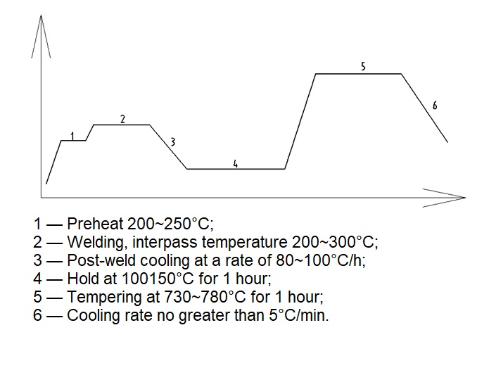
クラス 22 の場合、ベース材料は N & T または Q&T 状態であり、730°C 以上で焼戻しされます。
溶接は680~780°Cの範囲でPWHTします。
クラス42の場合、焼戻し温度は最低680°Cとなります。
P 0.01%最大を指定 |
| NPS 16以上のサイズの電気溶接1.25 Cr-0.5 Mo鋼管 |
600 |
A 691 – 1.25Cr クラス22または42 |
高温使用の場合、最適なクリープ耐性および/または水素攻撃に対する耐性が求められる |
クラス 22 の場合、ベース材料は N & T または Q&T 状態であり、730°C 以上で焼戻しされます。
溶接は680~780°Cの範囲でPWHTします。
クラス42の場合、焼戻し温度は最低680°Cとなります。
P 0.01% 最大を指定します。 |
| NPS 16以上のサイズの電気溶接2.25Cr鋼管 |
625 |
A 691 – 2.25 Cr クラス 22 または 42 |
高温使用の場合、最適なクリープ耐性および/または水素攻撃に対する耐性が求められる |
クラス 22 の場合、ベース材料は N & T または Q&T 状態であり、730°C 以上で焼戻しされます。
溶接は680~780°Cの範囲でPWHTします。
クラス42の場合、焼戻し温度は最低680°Cとなります。
P 0.01% 最大を指定します。 |
| NPS 16以上のサイズの電気溶接5Cr-0.5Mo鋼管 |
650 |
A 691 – 5 Cr クラス 22 または 42 |
高温使用および/または硫黄腐食耐性 |
クラス 22 の場合、ベース材料は N & T または Q&T 状態であり、730°C 以上で焼戻しされます。
溶接は680~780°Cの範囲でPWHTします。
クラス42の場合、焼戻し温度は最低680°Cとなります。
P 0.01% 最大を指定します。 |
| NPS 12以上のサイズの電気溶接18Cr-8Ni鋼管 |
-200 から +400 |
A 358 – グレード 304 または 304L クラス 1 |
特定の腐食条件および/または高温使用の場合 |
材料は、ASTM A262 に規定されている Practice E 粒界腐食試験に合格できる必要があります。 |
| NPS 12以上のサイズの電気溶接18Cr-8Ni安定化鋼管 |
-100 から +600 |
A 358 – グレード 321 または 347 クラス 1 |
特定の腐食条件および/または高温使用の場合 |
粒界腐食に対する最適な耐性を得るには、ASTM A358 に詳述されているように、溶体化熱処理後に 900°C で 4 時間の安定化熱処理を指定してください。補足要件 S6。材料は、ASTM A262 に規定されている Practice E 粒界腐食試験に合格できる必要があります。 |
| NPS 12以上のサイズの電気溶接18Cr-10Ni-2Mo鋼管 |
-200 から +500 |
A 358 – グレード 316 または 316L クラス 1 |
特定の腐食条件および/または高温使用の場合 |
材料は、ASTM A262 に規定されている Practice E 粒界腐食試験に合格できる必要があります。 |
| NPS 12以上のサイズの電気溶接18Cr-8Ni鋼管 |
-200 から +500 |
A 358 – グレード 304L クラス 1 |
特定の腐食条件および/または高温使用の場合 |
C 0.06% maxおよびMo+Ti+Nb 0.04% maxを指定します。 |
| シームレス0.3Mo鋼管 |
500 |
|
水素サービスには適していません。高温サービス用 |
総Al含有量0.012%以下を指定します。 |
| シームレス0.5Mo鋼管 |
500 |
A 335 – P1 |
水素サービスには適していません。高温サービス用 |
総Al含有量0.012%以下を指定します。 |
| シームレス1Cr-0.5Mo鋼管 |
500 |
A 335 – P12 |
高温使用および/または水素攻撃に対する耐性 |
正規化および焼き戻しを指定します。
水素攻撃に対する耐性については、API 941 を参照してください。
購入者は、サービスが
温度は600℃以上になる |
| シームレス 1.25 Cr-0.5 Mo 鋼管 |
600 |
A 335 – P11 |
高温使用および/または水素攻撃に対する耐性
シームレスは通常サイズが入手できない
NPS 16より大きい。より大きなサイズの場合は、ASTM A691 – 1.25 CRクラス22または42を使用してください。
(9.3.2). |
正規化および焼き戻しを指定します。
P 0.005% 最大を指定します。
水素攻撃に対する耐性についてはAPI 941を参照してください。
購入者は、サービスが
温度は600℃以上になる |
| シームレス 2.25 Cr-1 Mo 鋼管 |
625 |
A 335 – P22 |
高温使用の場合、最適なクリープ耐性および/または水素攻撃に対する耐性が求められる
通常、NPS 16 より大きいサイズではシームレスは入手できません。より大きなサイズの場合は、ASTM A691 – 2.25 Cr-クラス 22 または 42 を使用します (9.3.3 を参照)。 |
正規化および焼き戻しを指定します。
水素攻撃に対する耐性については、API 941 を参照してください。
購入者は、サービスが
温度は600℃以上になる |
| シームレス5Cr-0.5Mo鋼管 |
650 |
A 335 – P5 |
高温使用および/または硫黄腐食耐性
通常、NPS 16 より大きいサイズではシームレスは得られません。より大きなサイズの場合は、ASTM A691 – 5 Cr-Class 22 または 42 を使用します (9.3.4 を参照)。 |
焼入れ焼戻しまたは焼入れ焼戻しを指定します。 |
| シームレス9Cr-1Mo鋼管 |
650 |
A 335 – P9 |
高温使用および/または硫黄腐食耐性 |
正規化および焼き戻しを指定します。
購入者は、サービスが
温度は600℃以上になる |
| シームレス3.5Ni鋼管 |
400 |
A 333 – グレード3シームレス |
低い使用温度の場合 |
|
| シームレス9Ni鋼管 |
-200 |
A 333 – グレード8シームレス |
低い使用温度の場合 |
指定: C 0.10% 最大。S 0.002% 最大。P 0.005% 最大。 |
| NPS 12 までのサイズのシームレスおよび溶接 18 Cr-8 Ni 鋼管。 |
-200 から +400 |
A 312 – TP 304 |
低い使用温度または製品の汚染を防ぐため |
溶接パイプは壁厚 5.5 mm まで使用できます。
材料は、Practice Eに合格できるものでなければならない。
ASTM A 262に規定された粒界腐食試験 |
| NPS 12 までのサイズのシームレスおよび溶接 18 Cr-8 Ni 鋼管。 |
-200 から +400 |
A 312 – TP 304L |
特定の腐食条件および/または高温使用の場合 |
溶接パイプは壁厚 5.5 mm まで使用できます。
材料は、ASTM A 262に規定されているPractice E粒界腐食試験に合格できるものでなければならない。 |
| NPS 12 までのサイズのシームレスおよび溶接 18 Cr-8 Ni 安定化鋼管。 |
-100 から +600 |
A 312 – TP 321 または TP 347 |
特定の腐食条件および/または高温使用の場合 |
溶接パイプは壁厚 5.5 mm まで使用できます。
粒界腐食に対する最適な耐性を得るには、ASTM A358補足要件に詳述されているように、溶体化熱処理後に900°Cで4時間の安定化熱処理を指定してください。
S5 材料は、ASTM A 262に規定された試験法Eの粒界腐食試験に合格できるものでなければならない。 |
| NPS 12 までのサイズのシームレスおよび溶接 18 Cr-8 Ni 安定化鋼管。 |
815 |
A 312 – TP 321H または TP 347H |
特定の腐食条件および/または極端な使用温度の場合 |
溶接パイプは壁厚 5.5 mm まで使用できます。 |
| このグレードの使用には当社の同意が必要です。 |
| NPS 12 までのサイズのシームレスおよび溶接 18 Cr-10 Ni-2 Mo 鋼管。 |
-200 から +500 |
A 312 – TP 316 または TP 316L |
特定の腐食条件および/または高温使用の場合 |
溶接パイプは壁厚 5.5 mm まで使用できます。 |
| 材料は、ASTM A262 に規定されている Practice E 粒界腐食試験に合格できる必要があります。 |
| NPS 12 までのサイズのシームレスおよび溶接 18 Cr-8 Ni 鋼管。 |
+500 (+815) |
A 312 – TP 304H |
特定の腐食条件および/または高温使用の場合 |
C 0.06%以下、Mo+Ti+Nb 0.4%以下を指定します。 |
| シームレスおよび溶接22Cr-5Ni-Mo-N鋼管 |
300 |
A 790 – S 31803 |
特定の腐食条件の場合 |
N 0.15%以上を指定します。 |
| 溶接パイプは壁厚 5.5 mm まで使用できます。 |
| 溶体化処理および水冷処理の条件で指定します。 |
| シームレスおよび溶接25 Cr-7 Ni-Mo-N鋼管 |
300 |
A 790 – S 32750 |
特定の腐食条件の場合 |
N 0.15%以上を指定します。 |
| 溶接パイプは壁厚 5.5 mm まで使用できます。 |
| 溶体化処理および水冷処理の条件で指定します。 |
| シームレスおよび溶接20Cr-18Ni-6Mo-Cu-N鋼管 |
-200 (+400) |
A312 – S31254 |
特定の腐食条件の場合 |
溶接パイプは壁厚 5.5 mm まで使用できます。 |
鍛造品、フランジ、継手
| 指定 |
金属温度 (°C) |
国際規格 |
備考 |
追加された要件 |
| 0.5 Mo鋼突合せ溶接継手 |
500 |
A 234 – WP1 または WP1W |
水素サービスには対応していません。高温サービス用です。 |
NPS 16 までのサイズはシームレスである必要があります。
より大きなサイズは、シームレスまたは溶接のいずれかになります。
総Al含有量0.012%以下を指定します。 |
| 1 Cr-0.5 Mo鋼突合せ溶接継手 |
600 |
A 234 – WP12 クラス 2 または WP12W クラス 2 |
高い使用温度および/または水素攻撃に対する耐性。 |
NPS 16 までのサイズはシームレスである必要があります。
より大きなサイズは、シームレスまたは溶接のいずれかになります。
焼入れ焼戻しまたは焼入れ焼戻しを指定します。
P 0.005% 最大を指定します。
水素攻撃に対する耐性については、API 941 を参照してください。 |
| 1.25Cr-0.5Mo鋼突合せ溶接継手 |
600 |
A 234 – WP11 クラス 2 または WP11W クラス 2 |
高い使用温度および/または水素攻撃に対する耐性。 |
NPS 16 までのサイズはシームレスである必要があります。
P 0.005% 最大を指定します。
ウェルメタルの場合は、10P+55Pb+5Sn+As (1400 ppm) を指定します。 |
| 2.25 Cr-1 Mo鋼突合せ溶接継手 |
625 |
A 234 – WP22 クラス 3 または WP22W クラス 3 |
極端な使用温度および/または硫黄腐食に対する耐性。 |
NPS 16 までのサイズはシームレスである必要があります。
より大きなサイズは、シームレスまたは溶接のいずれかになります。
焼入れ焼戻しまたは焼入れ焼戻しを指定します。
水素攻撃に対する耐性については、API 941 を参照してください。 |
| 5 Cr-0.5 Mo鋼突合せ溶接継手 |
650 |
A 234 – WP5 または WP5W |
高温使用および/または硫黄腐食に対する耐性用。 |
NPS 16 までのサイズはシームレスである必要があります。
より大きなサイズは、シームレスまたは溶接のいずれかになります。
焼入れ焼戻しまたは焼入れ焼戻しを指定します。 |
| 3.5 Ni鋼突合せ溶接継手 |
(+400) |
A 420 – WPL3 または WPL3W |
低い使用温度用。 |
NPS 16 までのサイズはシームレスである必要があります。
より大きなサイズは、シームレスまたは溶接のいずれかになります。
正規化することを指定します。 |
| 9 Ni鋼突合せ溶接継手 |
-200 |
A 420 – WPL8 または WPL8W |
低い使用温度用。 |
NPS 16 までのサイズはシームレスである必要があります。
より大きなサイズは、シームレスまたは溶接のいずれかになります。
二重焼入れまたは焼入れ焼戻しを指定します。
C 0.10%最大、S 0.002%最大、P 0.005%最大を指定します。 |
| 18 Cr-8 Ni鋼突合せ溶接継手 |
-200 から +400 |
A 403 – WP304-S/WX/WU |
低い使用温度の場合、または製品の汚染を防ぐ場合。 |
NPS 16 までのサイズはシームレスである必要があります。
より大きなサイズは、シームレスまたは溶接のいずれかになります。
材料は、ASTM A262 に規定されている Practice E 粒界腐食試験に合格する必要があります。
オーステナイト系ステンレス鋼のすべてのシーム溶接をテストします。 |
| 18 Cr-8 Ni鋼突合せ溶接継手 |
-200 から +400 |
A 403 – WP304L-S/WX/WU |
特定の腐食条件および/または高い使用温度向け。 |
NPS 16 までのサイズはシームレスである必要があります。
より大きなサイズは、シームレスまたは溶接のいずれかになります。
材料は、ASTM A262 に規定されている Practice E 粒界腐食試験に合格できる必要があります。 |
| 18 Cr-8 Ni鋼突合せ溶接継手 |
815 |
A 403 – WP304H-S/WX/WU |
特定の腐食条件および/または極端な使用温度向け。 |
NPS 16 までのサイズはシームレスである必要があります。
より大きなサイズは、シームレスまたは溶接のいずれかになります。
指定: C 0.06% 最大および Mo+Ti+Nb 0.4% 最大。 |
| 18 Cr-8 Ni安定化鋼突合せ溶接継手 |
(-100) から +600 |
A 403 – WP321-S/WX/WU または WP347-S/WX/WU |
特定の腐食条件および/または極端な使用温度向け。 |
NPS 16 までのサイズはシームレスである必要があります。
より大きなサイズは、シームレスまたは溶接のいずれかになります。
粒界腐食に対する耐性を最適化するには、溶体化熱処理の後に 900°C で 4 時間の安定化熱処理を指定してください。 |
| 18 Cr-8 Ni安定化鋼突合せ溶接継手 |
815 |
A 403 – WP321H-S/WX/WU または WP347H-S/WX/WU |
特定の腐食条件および/または極端な使用温度向け。 |
このグレードの使用は当社の同意を条件とします。 |
| 18 Cr-10 Ni-2 Mo鋼突合せ溶接継手 |
-200 から +500 |
A 403 – WP316-S/WX/WU または WP316L-S/WX/WU |
特定の腐食条件および/または高使用条件向け。 |
NPS 16 までのサイズはシームレスである必要があります。
より大きなサイズは、シームレスまたは溶接のいずれかになります。
材料は、ASTM A262 に規定されている Practice E 粒界腐食試験に合格できる必要があります。 |
| 22 Cr-5 Ni-Mo-N鋼突合せ溶接継手 |
300 |
A815 – S31803 クラス WP-S または WP-WX |
特定の腐食条件向け。 |
NPS 16 までのサイズはシームレスである必要があります。
より大きなサイズは、シームレスまたは溶接のいずれかになります。
N 0.15%以上を指定します。 |
| 腐食環境用 25 Cr-7 Ni-Mo-N 鋼突合せ溶接継手 |
300 |
A815 – S32750 クラス WP-S または WP-WX |
腐食性環境向け。 |
シームレスを指定します。 |
| 20 Cr-18 Ni-6 Mo-Cu-N 鋼突合せ溶接継手 |
(-200) から +400 |
A403 – WPS 31254-S/WX/WU |
特定の腐食条件向け。 |
NPS 16 までのサイズはシームレスである必要があります。
より大きなサイズは、シームレスまたは溶接のいずれかになります。 |
| 0.5 Mo鋼鍛造品 |
500 |
A 182 -F1 |
水素サービスには適していません。チューブシート、フランジ、継手、バルブ、その他の高圧保持部品用。
使用温度 |
|
| 0.5 Mo鋼鍛造品 |
+500 |
A 336 – F1 |
ドラム鍛造品などの重い部品、高温での使用に適しています。水素での使用には適していません。 |
総Al含有量0.012%以下を指定します。 |
| 1 Cr-0.5 Mo鋼鍛造品 |
+600 |
A 182 – F12 クラス 2 |
高温使用時のチューブシート、フランジ、継手、バルブ、圧力保持部品に。水素攻撃に耐性があります。 |
焼き入れおよび焼戻しを指定します。水素攻撃に対する耐性については、API 941 を参照してください。 |
| 1 Cr-0.5 Mo鋼鍛造品 |
+600 |
A 336 – F12 |
ドラム鍛造品などの重い部品、高使用温度および/または水素攻撃に対する耐性向け。 |
焼き入れおよび焼戻しを指定します。水素攻撃に対する耐性については、API 941 を参照してください。 |
| 1.25 Cr-0.5 Mo鋼鍛造品 |
+600 |
A182 – F11 |
高温使用時のチューブシート、フランジ、継手、バルブ、圧力保持部品に。水素攻撃に耐性があります。 |
焼き入れおよび焼戻しを指定します。P 0.005% 以下を指定します。水素攻撃に対する耐性については、API 941 を参照してください。 |
| 1.25 Cr-0.5 Mo鋼鍛造品 |
+600 |
A 336 – F11 |
ドラム鍛造品などの重い部品、高使用温度および/または水素攻撃に対する耐性向け。 |
焼き入れ焼き戻しまたは焼入れ焼き戻しを指定します。液体焼き入れ焼き戻しグレードの使用は合意の対象となります。P 0.005% 最大を指定します。 |
| 2.25 Cr-1 Mo鋼鍛造品 |
+625 |
A182 – F22 |
高温使用時のチューブシート、フランジ、継手、バルブ、圧力保持部品に。水素攻撃に耐性があります。 |
正規化および焼き戻しを指定します。材料および製造要件については、API 934 を参照してください。 |
| 2.25 Cr-1 Mo鋼鍛造品 |
+625 |
A 336 – F22 |
ドラム鍛造品などの重い部品、高使用温度および/または水素攻撃に対する耐性向け。 |
焼き入れ焼き戻しまたは焼入れ焼き戻しを指定します。液体焼き入れ焼き戻しグレードの使用は合意の対象となります。API 934 を参照してください。 |
| 3 Cr-1 Mo鋼鍛造品 |
+625 |
A182 – F21 |
高温使用時のチューブシート、フランジ、継手、バルブ、圧力保持部品に。水素攻撃に耐性があります。 |
正規化および焼き戻しを指定します。材料および製造要件については、API 934 を参照してください。 |
| 5 Cr-0.5 Mo鋼鍛造品 |
+650 |
A 182 – F5 |
高温使用時のチューブシート、フランジ、継手、バルブ、圧力保持部品に。硫黄腐食に耐性があります。 |
正規化および焼き戻しを指定します。 |
| 3.5 Ni鋼鍛造品 |
(-400) |
A350 – LF3 |
低温使用時のチューブシート、フランジ、継手、バルブ、圧力保持部品用。 |
指定: C 0.10% 最大、Si 0.30% 最大、Mn 0.90% 最大、S 0.005% 最大。 |
| 9 Ni鋼鍛造品 |
(-200) |
A 522 – タイプI |
低温使用時のチューブシート、フランジ、継手、バルブ、圧力保持部品用。 |
指定: C 0.10% 最大、Si 0.30% 最大、Mn 0.90% 最大、S 0.005% 最大。 |
| 12Cr鋼鍛造品 |
+540 |
182 F6a |
特定の腐食条件向け。 |
|
| 12Cr鋼鍛造品 |
+540 |
A 182 – F6a |
腐食性条件および/または高温使用条件下でのチューブシート、フランジ、継手、バルブ、およびその他の圧力保持部品用。 |
材料は、ASTM A262 に規定されている Practice E 粒界腐食試験に合格できる必要があります。 |
| 18 Cr-8 Ni鋼鍛造品 |
-200 / +400 |
A182 – F304 |
低い使用温度の場合、または製品の汚染を防ぐ場合。 |
材料は、ASTM A262 に規定されている Practice E 粒界腐食試験に合格できる必要があります。 |
| 18 Cr-8 Ni鋼鍛造品 |
-200 / +400 |
A 182 – F304L |
特定の腐食条件および/または高い使用温度向け。 |
材料は、ASTM A262 に規定されている Practice E 粒界腐食試験に合格できる必要があります。 |
| 18 Cr-8 Ni鋼鍛造品 |
-200 / +500 |
A 182 – F304L |
腐食性条件および/または高温使用条件下でのチューブシート、フランジ、継手、バルブ、およびその他の圧力保持部品用。 |
材料は、ASTM A262 に規定されている Practice E 粒界腐食試験に合格できる必要があります。 |
| 18 Cr-8 Ni鋼鍛造品 |
+815 |
A 182 – F304H |
極端な使用温度下でのチューブシート、フランジ、継手、バルブ、その他の圧力保持部品に使用します。 |
C 0.06% 以下、Mo+Ti+Nb 0.4% 以下を指定します。 |
| 18 Cr-8 Ni安定化鋼鍛造品 |
+600 |
A 182 – F321 / F347 |
腐食性条件および/または高温使用条件下でのチューブシート、フランジ、継手、バルブ、およびその他の圧力保持部品用。 |
粒界腐食に対する最適な耐性を得るには、870 ~ 900°C で 4 時間の安定化熱処理と、その後の溶体化熱処理を指定します。材料は、ASTM A262 に規定されている Practice E 粒界腐食試験に合格できる必要があります。 |
| 18 Cr-8 Ni安定化鋼鍛造品 |
+815 |
A 182 – F321H / F347H |
極端な使用温度下でのチューブシート、フランジ、継手、バルブ、その他の圧力保持部品に使用します。 |
このグレードの使用には当社の同意が必要です。 |
| 18 Cr-10 Ni-2 Mo鋼鍛造品 |
-200 / +500 |
A182 – F316 |
特定の腐食条件および/または高い使用温度向け。 |
材料は、ASTM A262 に規定されている Practice E 粒界腐食試験に合格できる必要があります。 |
| 18 Cr-10 Ni-2 Mo鋼鍛造品 |
-200 / +500 |
A 182 – F316L |
特定の腐食条件および/または高い使用温度向け。 |
材料は、ASTM A262 に規定されている Practice E 粒界腐食試験に合格できる必要があります。 |
| 18 Cr-10 Ni-2 Mo鋼鍛造品 |
-200 / +500 |
A 182 – F316H |
特定の腐食条件および/または高い使用温度向け。 |
材料は、ASTM A262 に規定されている Practice E 粒界腐食試験に合格できる必要があります。 |
| 22 Cr-5 Ni-Mo-N鋼鍛造品 |
-30 / +300 |
A182 – F51 |
腐食環境下におけるチューブシート、フランジ、継手、バルブ、その他の圧力保持部品に使用します。 |
N 0.15%以上を指定します。 |
| 25 Cr-7 Ni-Mo-N鋼鍛造品 |
(-30) から +300 |
A182 – F53 |
特定の腐食条件下でのチューブシート、フランジ、継手、バルブ、およびその他の圧力保持部品用。 |
– |
| 20 Cr-18 Ni-6 Mo-Cu-N 鋼鍛造品 |
(-200) から (+400) |
A182 – F44 |
特定の腐食条件下でのチューブシート、フランジ、継手、バルブ、およびその他の圧力保持部品用。 |
– |
| 9CrMo鋼鍛造品 |
+650 |
ASTM A182-F9 |
極端な使用温度や硫黄腐食に対する耐性が必要なチューブシート、フランジ、継手、バルブ、その他の圧力保持部品用。 |
標準化され、強化された |
| 腐食環境用鍛造Ni-Cr-Mo-Nb合金(合金625) |
425 |
ASTM B366 |
化学的に不動態化されており、スケールや酸化物は一切ありません。溶体化処理された状態で指定してください。 |
– |
| 腐食環境用Ni-Cr-Fe合金(合金600)鍛造品 |
+650 |
ASTM B564 N06600 |
溶体化処理された状態の鍛造品を指定します。 |
– |
鋳造品
| 指定 |
金属温度 (°C) |
ASTM仕様 |
備考 |
追加された要件 |
| 14.5 Si鋳物 |
+250 |
518 – 1 |
非圧力保持(内部)部品用。 |
Si 含有量 14.5% 以上を指定します。特定の Mo に対するその他の合金元素。 |
| 18-16-6 Cu-2 Cr-Nb(タイプ1)鋳物 |
+500 |
A 436 – タイプ1 |
特定の腐食条件下での非圧力保持(内部)部品用。 |
– |
| 18-20 Cr-2 Ni-Nb-Ti (タイプ D-2) 鋳物 |
+500 |
A 439 – タイプD-2 |
特定の腐食条件下での圧力保持部品用。 |
– |
| 22 Ni-4Mn鋳物 |
+500 |
A 571 – タイプD2-M |
低い使用温度での圧力保持部品用。 |
– |
| 0.5 Mo鋼鋳物 |
+500 |
A 217 – WC1 |
水素サービスには適していません。高温での使用や水素攻撃に対する耐性が必要な継手、バルブ、その他の圧力保持部品に適しています。 |
総Al含有量0.012%以下を指定します。 |
| 1.25 Cr-0.5 Mo鋼鋳物 |
+550 |
A 217 – WC6 |
高温での使用や硫黄腐食に対する耐性が必要な継手、バルブ、その他の圧力保持部品用。 |
最大0.01%を指定します。Al。焼き入れおよび焼戻し済み。 |
| 2.25 Cr-1 Mo鋼鋳物 |
+650 |
A 217 – WC9 |
高温での使用や水素攻撃に対する耐性が必要な継手、バルブ、その他の圧力保持部品用。 |
API 941 に従って、最大 0.01% の水素攻撃耐性を指定します。 |
| 5 Cr-0.5 Mo鋼鋳物 |
+650 |
A 217 – C5 |
高温での使用や硫黄腐食に対する耐性が必要な継手、バルブ、その他の圧力保持部品用。 |
– |
| 9 Cr-1 Mo鋼鋳物 |
+650 |
A 217 – C12 |
高温での使用や硫黄腐食に対する耐性が必要な継手、バルブ、その他の圧力保持部品用。 |
– |
| 3.5 Ni鋼鋳物 |
(+400) |
A 352 – LC3 |
低い使用温度用。 |
– |
| 9 ニッケル鋼鋳物 |
(+400) |
A 352 – LC9 |
低い使用温度用。 |
指定: C 0.10% 最大、S 0.002% 最大、P 0.005% 最大。 |
| 12Cr鋼鋳物 |
+540 |
A743 – CA15 |
腐食性条件下での非圧力保持部品用。 |
– |
| 12 Cr-4 Ni鋼鋳物 |
+540 |
A 217 – CA15 |
特定の腐食条件下での圧力保持部品用。 |
– |
| 18 Cr-8 Ni鋼鋳物 |
+200 |
A 744 – CFB |
特定の腐食条件下および/または高い使用温度下での非圧力保持(内部)部品用。 |
腐食性用途の鋳造品は、ASTM A262、Practice E の要件を満たす必要があります。 |
| 18 Cr-10 Ni-Nb(安定化)鋼鋳物 |
+1000 |
A 744 – CFBC |
水素サービス用の場合は、水素攻撃に対する耐性のために、最大 0.012% の Al 含有量を指定します。腐食サービス用の鋳物は、ASTM A262、Practice E の要件を満たす必要があります。 |
|
| 18 Cr-10 Ni-2 Mo鋼鋳物 |
+500 |
A 744 – CBFM |
特定の腐食条件下および/または高い使用温度下での非圧力保持(内部)部品用。 |
腐食性用途の鋳造品は、ASTM A262、Practice E の要件を満たす必要があります。 |
| 25 Cr-20 Ni鋼鋳物 |
+1000 |
A 297 – 香港 |
耐熱性を必要とする非保圧(内部)部品用。 |
– |
| 25 Cr-12 Ni鋼鋳物 |
+1000 |
A447-タイプII |
炉管支持用。 |
|
| 18 Cr-8 Ni鋼鋳物 |
-200 から +500 |
A351-CF8 |
特定の腐食条件下および/または高い使用温度下での圧力保持部品用。 |
腐食性用途の鋳造品は、ASTM A262、Practice E の要件を満たす必要があります。 |
| 18 Cr-8 Ni-Nb安定化鋼鋳物 |
(-100) から +600 |
A351-CF8C |
特定の腐食条件下および/または高い使用温度下での圧力保持部品用。 |
500°C を超える動作温度で使用する場合、特定の Si 含有量は最大 1.0% です。腐食性サービス用の鋳物は、ASTM A262、Practice E の要件を満たす必要があります。 |
| 18 Cr-10 Ni-2 Mo鋼鋳物 |
-200 から +500 |
A351-CF8M |
特定の腐食条件下および/または高い使用温度下での圧力保持部品用。 |
腐食性用途の鋳造品は、ASTM A262、Practice E の要件を満たす必要があります。 |
| 22 Cr-5 Ni-Mo-N鋼鋳物 |
+300 |
A890-4A、S32、S33 |
特定の腐食条件下での圧力保持部品用。 |
|
| 25 Cr-7 Ni-Mo-N鋼鋳物 |
+300 |
A890-5A、S32、S33 |
特定の腐食条件下での圧力保持部品用。 |
|
| 20 Cr-18 Ni-6 Mo-Cu-N 鋼鋳物 |
(-200) から (+400) |
A351-CK3MCuN |
特定の腐食条件下での圧力保持部品用。 |
|
| 25 Cr-20 Ni鋼鋳物 |
+1000 |
A351-CH20 |
極端な使用温度における特定の腐食条件下での圧力保持部品用。 |
|
| 25 Cr-20 Ni鋼鋳物 |
+1000 |
A351-CK20 |
極端な使用温度における特定の腐食条件下での圧力保持部品用。 |
|
| 25 Cr-20 Ni鋼鋳物 |
+1000 |
A351-HK40 |
極端な使用温度における特定の腐食条件下での圧力保持部品用。 |
|
| 20 Cr-29 Ni-Mo-Cu 鋼鋳物 |
(+400) |
A744-CN7M |
硫酸腐食に対する耐性が求められる継手、バルブ、その他の圧力保持部品に。 |
|
Cr-Ni鋼遠心鋳造および静的鋳造
20 Cr-33 ニッケル-ニオブ
25 Cr-30 Ni
25 Cr-35 ニッケル-ニオブ |
|
|
極端な使用温度での圧力保持炉部品用。 |
|
バー、セクション、ワイヤー
| 指定 |
金属温度 (°C) |
国際規格 |
備考 |
追加要件 |
| 1 Cr-0.25 Mo鋼棒 |
+450 (+540) |
322 – 4140 |
機械加工部品用 |
|
| 9 Ni鋼棒 |
-200 |
322 号 |
機械加工部品、低温サービス用 |
|
| 12 Cr鋼棒 |
+425 |
A 276 – タイプ410またはタイプ420 |
切削性はASTM A582、タイプ416または416Seに適合し、当社の承認が必要です。 |
溶接品の場合はタイプ405を指定してください |
| 18 Cr-8 Ni鋼棒 |
-200 から +500 |
A 479 – タイプ304 |
機械加工部品用 |
材料はASTM A262 Practice Eの要件を満たすことができるものとする。 |
| 18 Cr-8 Ni鋼棒 |
-200 から +500 |
A 479 – タイプ304L |
機械加工部品用 |
材料はASTM A262 Practice Eの要件を満たすことができるものとする。 |
| 18 Cr-8 Ni鋼棒 |
+500 (+815) |
A 479 – タイプ304H |
機械加工部品用 |
C: 0.06% 最大、Mo+Ti+Nb: 0.4% 最大を指定します。 |
| 18 Cr-8 Ni安定化鋼棒 |
-200 (+815) |
A 479 – タイプ321またはタイプ347 |
機械加工部品用 |
材料はASTM A262 Practice Eの要件を満たすことができるものとする。 |
| 18 Cr-8 Ni安定化鋼棒 |
+500 (+815) |
A 479 – タイプ321Hまたはタイプ347H |
機械加工部品の場合、このグレードの使用は当社の同意に従うものとします。 |
|
| 18 Cr-10 Ni-2 Mo鋼棒 |
-200 から +500 |
A 479 – タイプ316 |
機械加工部品用 |
材料はASTM A262 Practice Eの要件を満たすことができるものとする。 |
| 18 Cr-10 Ni-2 Mo鋼棒 |
-200 から +500 |
A 479 – タイプ316L |
機械加工部品用 |
材料はASTM A262 Practice Eの要件を満たすことができるものとする。 |
| 22 Cr-5 Ni-Mo-N鋼棒 |
-30 から +300 |
A479 – S31803 |
機械加工部品用 |
N 0.15%以上 |
| 25 Cr-7 Ni-Mo-N鋼棒 |
-30 から +300 |
A479 – S32750 |
機械加工部品用 |
N 0.15%以上 |
| 20 Cr-18 Ni-6 Mo-Cu-N 鋼棒 |
-200 (+400) |
A 276 – S31254 |
機械加工部品用 |
|
| Si-Mn鋼棒 |
+230 |
A689/A322-9260 |
スプリング用 |
|
| 冷間引抜鋼線 |
+230 |
227 号 |
スプリング用 |
|
| 冷間引抜18Cr-8Ni鋼線 |
+230 |
タイプ302 |
スプリング用 |
材料はASTM A262 Practice Eの要件を満たすことができるものとする。 |
ボルト締め
| 指定 |
金属温度 (°C) |
国際規格 |
備考 |
追加された要件 |
| 1 Cr-0.25 Mo鋼ボルト材 |
+450 (+540) |
A 193 – B7 |
一般的な用途向け。ナットについては8.7.3を参照してください。 |
– |
| 1 Cr-0.25 Mo鋼ボルト材 |
+450 (+540) |
A 193 – B7M |
酸味のあるサービス用。ナッツについては9.7.13を参照。 |
– |
| 1 Cr-0.5 Mo-0.25鋼ボルト材 |
+525 (+600) |
A 193 – B16 |
高温用途向け。ナットについては9.7.14を参照。 |
– |
| 1 Cr-0.25 Mo鋼ボルト材 |
-105 から +450 (+540) |
A 320 – L7 |
低温サービス用。ナットについては9.7.15を参照してください。 |
– |
| 1 Cr-0.25 Mo鋼ボルト材 |
-30 から +450 |
A 320 – L7M |
酸味のあるサービスおよび低温のサービス用。ナッツについては9.7.16を参照。 |
– |
| 9 Ni鋼ボルト材 |
-200 |
– |
低温サービス用。ナットについては9.7.17を参照してください。 |
– |
| 12Cr鋼ボルト材 |
+425 (+540) |
A 193 – B6X |
特定の腐食条件用。ナットについては9.7.18を参照してください。 |
– |
| 18 Cr-8 Ni鋼(ひずみ硬化)ボルト材質 |
-200 から +815 |
A 193 – B8 クラス 2 |
特定の腐食条件および/または極端な温度環境での使用に適しています。ナットについては 9.7.19 を参照してください。 |
材料は、ASTM A262 Practice E の要件を満たす必要があります。 |
| 18 Cr-8 Ni安定化鋼ボルト材 |
-200 から +815 |
A 193 – B8T または B8C |
特定の腐食条件および/または極端な温度環境での使用に適しています。ナットについては 9.7.21 を参照してください。 |
材料は、ASTM A262 Practice E の要件を満たす必要があります。 |
| 18 Cr-10 Ni-2 Mo鋼(ひずみ硬化)ボルト材 |
-200 から +500 |
A 193 – BBM クラス 2 |
特定の腐食条件および/または高温環境での使用に適しています。ナットについては、9.7.22 を参照してください。 |
材料は、ASTM A262 Practice E の要件を満たす必要があります。 |
| 18 Cr-8 Ni鋼ボルト材 |
-200 |
A 193 – BBN |
低温サービス用。ナットについては9.7.20を参照してください。 |
材料は、ASTM A262 Practice E の要件を満たす必要があります。 |
| 析出硬化型オーステナイト系Ni-Cr鋼ボルト材 |
+540 |
453-660 クラスA |
特定の腐食条件および/または高温サービス向け。膨張係数はオーステナイト鋼と同等です。ナットについては 9.7.23 を参照してください。 |
– |
| 0.25 Mo鋼ナット |
+525 |
A 194 – 2HM |
9.7.2 に規定する材料で作られたボルト用。 |
– |
| 0.25 Mo鋼ナット |
+525 (+600) |
194 – 4 |
9.7.3に規定された材料で作られたボルトの場合 |
– |
| 0.25 Mo鋼ナット |
-105 から +525 (+540) |
A 194 – 4、S4 |
9.7.4に規定された材料で作られたボルトの場合 |
– |
| 0.25 Mo鋼ナット |
+525 |
A 194 – 7M、S4 |
9.7.5に規定された材料で作られたボルトの場合 |
– |
| 9 Ni鋼ナット |
-200 |
– |
9.7.6に規定された材料で作られたボルトの場合 |
– |
| 12 Cr鋼ナット |
+425 (+540) |
194 – 6 |
9.7.7 に規定された材料で作られたボルト用。当社の承認があれば、切削性グレード 6F も使用可能です。 |
– |
| 18 Cr-8 Ni鋼(ひずみ硬化)ナット |
-200 から +815 |
A 194 – 8、S1 |
9.7.8 に規定された材料で作られたボルト用。当社の承認があれば、切削性グレード 8F も使用可能です。 |
材料は、ASTM A262 Practice E の要件を満たす必要があります。 |
| 18 Cr-8 Ni鋼ナット |
-200 |
A 194 – 8N |
低温サービス用。 |
材料は、ASTM A262 Practice E の要件を満たす必要があります。 |
| 18 Cr-8 Ni安定化鋼ナット |
-200 から +815 |
A 194 – 8T または 8C |
9.7.9 に規定された材料で作られたボルト用。当社の承認があれば、切削性グレード 8F も使用可能です。 |
材料は、ASTM A262 Practice E の要件を満たす必要があります。 |
| 18 Cr-10 Ni-2 Mo鋼(ひずみ硬化)ナット |
-200 から +500 |
A 194 – 8M、S1 |
9.7.10に規定された材料で作られたボルトの場合 |
材料は、ASTM A262 Practice E の要件を満たす必要があります。 |
| 析出硬化型オーステナイト系Ni-Cr鋼ナット |
+540 |
453-660 クラスA |
9.7.12に規定された材料で作られたボルトの場合 |
– |
| 低温用途向け0.75 Cr-1.75 Ni、0.25 Mo鋼ボルト材 |
+400 |
A320-L43 |
– |
– |
材料選択ガイドライン: 非鉄金属
プレート、シート、ストリップ
| 指定 |
金属温度 (°C) |
国際規格 |
備考 |
追加された要件 |
| アルミニウム板およびシート |
-200 から +200 |
B 209 – 合金1060 |
特定の腐食条件の場合 |
すべてのグレードに対して焼鈍条件を指定します。 |
| Al-2.5Mg合金板およびシート |
-200 から +200 |
B 209 – 合金5052 |
特定の腐食条件下での一般的な使用向け |
すべてのグレードに対して焼鈍条件を指定します。 |
| Al-2.7Mg-Mn合金板およびシート |
-200 から +200 |
B 209 – 合金5454 |
特定の腐食条件下での一般的な使用向け |
すべてのグレードに対して焼鈍条件を指定します。 |
| Al-4.5Mg-Mn合金板およびシート |
-200 から +65 |
B 209 – 合金5083 |
低温用途向け |
すべてのグレードに対して焼鈍条件を指定します。 |
| 銅板、銅シート、銅ストリップ |
-200 から +150 |
B152 – C12200 |
特定の腐食条件の場合 |
すべてのグレードに対して焼鈍条件を指定します。 |
| Cu-Zn合金板およびシート |
-200 から +175 |
B 171 – C46400 |
汽水および海水サービスにおける冷却器および凝縮器のバッフル、および特定の腐食条件下での一般的な使用向け |
すべてのグレードに対して焼鈍条件を指定します。 |
| Cu-Al合金板およびシート |
-200 から +250 |
B 171 – C61400 |
甘水および汽水サービスにおける冷却器および凝縮器のチューブシート、および特定の腐食条件下での一般的な使用向け |
すべてのグレードに対して焼鈍条件を指定します。 |
| Cu-Al合金板およびシート |
-200 から +350 |
B 171 – C63000 |
汽水および海水サービスにおける冷却器および凝縮器のチューブシート、および特定の腐食条件下での一般的な使用向け。機械特性と化学組成がこの仕様に適合していれば、承認された製造業者による特殊な鋳造方法で製造されたチューブシートが許容されます。 |
Al含有量最大10.0%。 |
| Cu-Ni(90/10)合金板およびシート |
-200 から +350 |
B171 – C70600 |
汽水および海水サービスにおける冷却器および凝縮器のチューブシート、および特定の腐食条件下での一般的な使用向け |
– |
| Cu-Ni(70/30)合金板およびシート |
-200 から +350 |
B 171 – C71500 |
特定の腐食条件の場合 |
– |
| ニッケル板、シート、ストリップ |
-200 から (+350) |
B 162 – N02200 |
特定の腐食条件の場合 |
すべてのグレードに対して焼鈍条件を指定します。 |
| 低炭素ニッケル板、シート、ストリップ |
-200 から (+350) |
B 162 – N02201 |
特定の腐食条件の場合 |
すべてのグレードに対して焼鈍条件を指定します。 |
| ニッケル銅合金 |
-200 |
B 127 – |
特定の腐食条件の場合 |
すべてのグレードに対して焼鈍条件を指定します。 |
| モネル(400)プレート、シート、ストリップ |
+400 |
N04400 |
特定の腐食条件の場合 |
すべてのグレードに対して焼鈍条件を指定します。 |
| Ni-Cr-Fe合金(インコネル600)板、シート、ストリップ |
+650 |
B 168 – N06600 |
高温条件および/または特定の腐食条件の場合 |
すべてのグレードの焼鈍条件を指定します |
| Ni-Fe-Cr合金(インコロイ800)板、シート、ストリップ |
+815 |
B409 – N08800 |
高温条件および/または特定の腐食条件の場合 |
C 0.05%を最大に指定し、すべてのグレードの焼鈍条件を指定します。 |
| Ni-Fe-Cr合金(インコロイ800H)板、シート、ストリップ |
+1000 |
B 409 – N08810 |
高温条件および/または特定の腐食条件の場合 |
すべてのグレードの焼鈍条件を指定します |
| Ni-Fe-Cr合金(インコロイ800HT)板、シート、ストリップ |
(+1000) |
B 409 – N08811 |
高温条件および/または特定の腐食条件の場合 |
すべてのグレードの焼鈍条件を指定します |
| Ni-Fe-Cr-Mo-Cu合金(インコロイ825)板、シート、ストリップ |
+425 |
B 424 – N08825 |
特定の腐食条件の場合 |
材料は、ASTM A262 に準拠した Practice C 粒界腐食試験に合格する必要があります (腐食速度 ≤ 0.3 mm/年) |
| Ni-Cr-Mo-Nb合金(インコネル625)板、シート、ストリップ |
+425 |
B 443 – N06625 |
特定の腐食条件の場合 |
該当なし |
| Ni-Mo合金(ハステロイB2)板、シート、ストリップ |
+425 |
B 333 – N10665 |
特定の腐食条件の場合 |
該当なし |
| Ni-Mo-Cr合金(ハステロイC4)板、シート、ストリップ |
+425 |
B575 – N06455 |
特定の腐食条件の場合 |
該当なし |
| Ni-Mo-Cr合金(ハステロイC276)板、シート、ストリップ |
+425 (+650) |
B575 – N10276 |
特定の腐食条件の場合 |
該当なし |
| Ni-Cr-Mo合金(ハステロイC22)板、シート、ストリップ |
(+425) |
B575 – N06022 |
特定の腐食条件の場合 |
該当なし |
| チタン板、シート、ストリップ |
(+300) |
B 265 – グレード 2 |
特定の腐食条件の場合、ライニングの場合、材料仕様に示されている引張特性は情報のみを目的としています。 |
ライニングには、硬度140 HV10以下の軟質焼鈍材を指定してください。より柔らかいグレード1もライニングに使用できます。 |
| タンタル板、シート、ストリップ |
温度制限はサービスによって異なります |
B 708 – R05200 |
特定の腐食条件の場合、ライニングの場合、材料仕様に示されている引張特性は情報のみを目的としています。 |
ライニングには、硬度120 HV10以下の軟質焼鈍材を指定してください。 |
チューブとチューブ
| 指定 |
金属温度 (°C) |
国際規格 |
備考 |
追加された要件 |
| シームレスアルミチューブ |
-200 から +200 |
B 234 – 合金1060 |
特定の腐食条件下での非加熱熱伝達装置用 |
すべてのグレードの焼鈍条件を指定します |
| シームレスAl-2.5Mg合金管 |
-200 から +200 |
B 234 – 合金5052 |
特定の腐食条件下での非加熱熱伝達装置用 |
すべてのグレードの焼鈍条件を指定します |
| シームレスAl-2.7Mg-Mn合金管 |
-200 から +200 |
B 234 – 合金5454 |
特定の腐食条件下での非加熱熱伝達装置用 |
すべてのグレードの焼鈍条件を指定します |
| 小型サイズのシームレス銅管 |
-200 から +150 |
B 68 – C12200 06 0 |
計器ライン用 |
すべてのグレードの焼鈍条件を指定します |
| シームレスCu-Zn-Al合金(アルミニウム真鍮) |
(+200) から +175 |
B111 – C68700 |
汽水および海水サービスの冷却器および凝縮器用 |
すべてのグレードの焼鈍条件を指定します |
| シームレス銅ニッケル(90/10 Cu-Ni)合金管 |
-200 から +350 |
B111 – C70600 |
特定の腐食条件下での非加熱熱伝達装置用 |
すべてのグレードの焼鈍条件を指定します |
| シームレス銅ニッケル(70/30 Cu-Ni)合金管 |
-200 から +350 |
B 111 – C71500 |
特定の腐食条件下での非加熱熱伝達装置用 |
すべてのグレードの焼鈍条件を指定します |
| シームレス銅ニッケル(66/30/2/2 Cu-Ni-Fe-Mn)合金管 |
-200 から +350 |
B 111 – C71640 |
特定の腐食条件下での非加熱熱伝達装置用 |
すべてのグレードの焼鈍条件を指定します |
| シームレスニッケル管 |
-200 から +350 |
B163 – N02200 |
特定の腐食条件下での非加熱熱伝達装置用 |
すべてのグレードについて溶体化処理条件を指定します。圧縮継手に使用するチューブの場合、硬度は90 HRBを超えてはなりません。 |
| シームレス低炭素ニッケル管 |
-200 から +350 |
B 163 – N02201 |
特定の腐食条件下での非加熱熱伝達装置用 |
すべてのグレードについて溶体化処理条件を指定します。圧縮継手に使用するチューブの場合、硬度は90 HRBを超えてはなりません。 |
| シームレスNi-Cu合金(モネル400)チューブ |
-200 から +400 |
B163 – N04400 |
特定の腐食条件下での非加熱熱伝達装置用 |
すべてのグレードについて溶体化処理条件を指定します。圧縮継手に使用するチューブの場合、硬度は90 HRBを超えてはなりません。 |
| シームレスNi-Cr-Fe合金(インコネル600)チューブ |
+650 |
B 163 – N06600 |
特定の腐食条件下での非加熱熱伝達装置用 |
すべてのグレードについて溶体化処理条件を指定します。圧縮継手に使用するチューブの場合、硬度は90 HRBを超えてはなりません。 |
| シームレスNi-Fe-Cr合金(インコロイ800)チューブ |
+815 |
B 163 – N08800 |
特定の腐食条件下での非加熱熱伝達装置用 |
最大C 0.05%を指定します。すべてのグレードで溶体化処理条件を指定します。圧縮継手で使用することを目的としたチューブの場合、硬度は90 HRBを超えてはなりません。 |
| シームレスNi-Fe-Cr合金(インコロイ800H)チューブ |
+1000 |
B 407 – N08810 |
特定の腐食条件下での炉および非加熱熱伝達装置用 |
すべてのグレードについて溶体化処理条件を指定します。圧縮継手に使用するチューブの場合、硬度は90 HRBを超えてはなりません。 |
| シームレスNi-Fe-Cr合金(インコロイ800 HT)チューブ |
(+1000) |
B 407 – N08811 |
特定の腐食条件下での炉および非加熱熱伝達装置用 |
すべてのグレードについて溶体化処理条件を指定します。圧縮継手に使用するチューブの場合、硬度は90 HRBを超えてはなりません。 |
| シームレスNi-Cr-Mo-Cu合金(インコロイ825)チューブ |
-200 から +425 |
B 163 – N08825 |
特定の腐食条件下での非加熱熱伝達装置用 |
チューブをヘッドボックスに溶接する場合は、安定化焼鈍条件を指定します。粒界腐食試験を実施します。 |
| シームレスNi-Cr-Mo-Nb合金(インコネル625)チューブ |
+425 |
B 444 – N06625 |
特定の腐食条件下での非加熱熱伝達装置用 |
グレード1(焼鈍)材料は、539°C以下の使用温度で使用する必要があります。粒界腐食試験を実施する必要があります。 |
| シームレスNi-Mo合金(ハステロイB2)チューブ |
+425 |
B622 – N10665 |
特定の腐食条件下での非加熱熱伝達装置用 |
粒界腐食試験を実施する |
| 溶接Ni-Mo合金(ハステロイB2)チューブ |
+425 |
B 626 – N10665 クラス 1A |
特定の腐食条件下での非加熱熱伝達装置用 |
粒界腐食試験を実施する |
| シームレスNi-Mo-Cr合金(ハステロイC4)チューブ |
+425 |
B 622 – N06455 |
特定の腐食条件下での非加熱熱伝達装置用 |
粒界腐食試験を実施する |
| 溶接Ni-Mo-Cr合金(ハステロイC4)チューブ |
+425 |
B 626 – N06455 クラス 1A |
特定の腐食条件下での非加熱熱伝達装置用 |
粒界腐食試験を実施する |
| シームレスNi-Mo-Cr合金(ハステロイC276)チューブ |
+425 (+650) |
B622 – N10276 |
特定の腐食条件下での非加熱熱伝達装置用 |
すべてのグレードについて溶体化処理条件を指定します。圧縮継手に使用するチューブの場合、硬度は90 HRBを超えてはなりません。 |
| 溶接Ni-Mo-Cr合金(ハステロイC276)チューブ |
+425 (+650) |
B 626 – N10276 クラス 1A |
特定の腐食条件下での非加熱熱伝達装置用 |
すべてのグレードについて溶体化処理条件を指定します。圧縮継手に使用するチューブの場合、硬度は90 HRBを超えてはなりません。 |
| シームレスNi-Cr-Mo合金(ハステロイC22)チューブ |
(+425) |
B 622 – N06022 |
特定の腐食条件下での非加熱熱伝達装置用 |
粒界腐食試験を実施する |
| 溶接Ni-Cr-Mo合金(ハステロイC22)チューブ |
(+425) |
B 626 – N06022 クラス 1A |
特定の腐食条件下での非加熱熱伝達装置用 |
粒界腐食試験を実施する |
| シームレスチタンチューブ |
(+300) |
B 338 – グレード 2 |
特定の腐食条件下での非加熱熱伝達装置用 |
該当なし |
| 溶接チタン管 |
(+300) |
B 338 – グレード 2 |
特定の腐食条件下での非加熱熱伝達装置用 |
該当なし |
パイプ
| 指定 |
金属温度 (°C) |
国際規格 |
備考 |
追加された要件 |
| シームレスアルミパイプ |
-200 から +200 |
B 241 – 合金1060 |
特定の腐食条件の場合 |
すべてのグレードに対して焼鈍条件を指定します。 |
| シームレスAl-Mg-Si合金パイプ |
-200 から +200 |
B 241 – 合金6061 |
特定の腐食条件の場合 |
すべてのグレードに対して焼鈍条件を指定します。 |
| シームレスAl-Mg-Si合金パイプ |
-200 から +200 |
B 241 – 合金6063 |
特定の腐食条件下のパイプライン用 |
すべてのグレードに対して焼鈍条件を指定します。 |
| シームレスAl-Mg合金パイプ |
-200 から +200 |
B 241 – 合金5052 |
特定の腐食条件下での一般的な使用向け |
すべてのグレードに対して焼鈍条件を指定します。 |
| シームレスAl-2.7Mg-Mn合金パイプ |
-200 から +200 |
B 241 – 合金5454 |
特定の腐食条件下での一般的な使用向け |
すべてのグレードに対して焼鈍条件を指定します。 |
| シームレスAl-4.5Mg-Mn合金パイプ |
-200 から +65 |
B 241 – 合金5083 |
低温サービスのみ |
すべてのグレードに対して焼鈍条件を指定します。 |
| シームレス銅管 |
-200 から +200 |
B42 – C12200 |
特定の腐食条件の場合 |
すべてのグレードに対して焼鈍条件を指定します。 |
| シームレスCu-Zn-Al合金管(アルミニウム黄銅) |
-200 から +175 |
B111 – C68700 |
汽水および海水サービス向け |
すべてのグレードに対して焼鈍条件を指定します。 |
| シームレスCu-Ni合金(90/10 Cu-Ni)パイプ |
-200 から +350 |
B466 – C70600 |
海水サービス用 |
すべてのグレードに対して焼鈍条件を指定します。 |
| シームレスCu-Ni合金(70/30 Cu-Ni)パイプ |
-200 から +350 |
B466 – C71500 |
特定の腐食条件の場合 |
すべてのグレードに対して焼鈍条件を指定します。 |
| シームレスニッケルパイプ |
-200 から +350 |
B 161 – N02200 |
特定の腐食条件の場合 |
すべてのグレードについて、冷間加工、焼鈍、酸洗処理の状態を指定します。 |
| シームレス低炭素ニッケル管 |
-200 から +350 |
B 161 – N02201 |
特定の腐食条件の場合 |
すべてのグレードについて、冷間加工、焼鈍、酸洗処理の状態を指定します。 |
| シームレスNi-Fe-Cr合金(インコロイ800)パイプ |
-200 から +815 |
B407 – N08800 |
高温条件および/または特定の腐食条件の場合 |
すべてのグレードに対して、冷間加工、焼鈍、酸洗処理を施した状態を指定します。C 0.05% 最大を指定します。 |
| シームレスNi-Fe-Cr合金(インコロイ800H)パイプ |
+1000 |
B 407 – N08810 |
高温条件および/または特定の腐食条件の場合 |
すべてのグレードについて、冷間加工、焼鈍、酸洗処理の状態を指定します。 |
| シームレスNi-Fe-Cr合金(インコロイ800HT)パイプ |
+1000 |
B 407 – N08811 |
高温条件および/または特定の腐食条件の場合 |
すべてのグレードについて、冷間加工、焼鈍、酸洗処理の状態を指定します。 |
| シームレスNi-Cr-Fe合金(インコネル600)パイプ |
+650 |
B 167 – N06600 |
高温条件および/または特定の腐食条件の場合 |
すべてのグレードについて、冷間加工、焼鈍、酸洗処理の状態を指定します。 |
| 銅合金(モネル400)パイプ |
+400 |
N04400 |
特定の腐食条件の場合 |
すべてのグレードについて、焼鈍および酸洗条件を指定します。 |
| シームレスNi-Fe-Cr-Mo-Cu合金(インコロイ825)パイプ |
-200 から +425 |
B 423 – N08825 |
特定の腐食条件の場合 |
すべてのグレードについて、冷間加工、焼鈍、酸洗処理を施した状態を指定します。粒界腐食試験 (ASTM A262) に合格する必要があります。腐食速度は 0.3 mm/年以下です。 |
| Ni-Fe-Cr-Mo-Cu合金(インコロイ825)溶接パイプ |
-200 から +425 |
B 705 – N08825 クラス2 |
特定の腐食条件の場合 |
冷間加工および光輝焼鈍処理された状態を指定します。粒界腐食試験 (ASTM A262) に合格する必要があります。腐食速度は 0.3 mm/年以下です。 |
| シームレスNi-Cr-Mo-Nb合金(インコネル625)パイプ |
+425 |
B 444 – N06625 |
特定の腐食条件の場合 |
すべてのグレードに対して、冷間加工および光輝焼鈍処理の状態を指定します。 |
| 溶接Ni-Cr-Mo-Nb合金(インコネル625)パイプ |
+425 |
B 705 – N06625 クラス2 |
特定の腐食条件の場合 |
冷間加工および光輝焼鈍処理の状態を指定します。 |
| シームレスNi-Mo合金(ハステロイB2)パイプ |
+425 |
B622 – N10665 |
特定の腐食条件の場合 |
|
| 溶接Ni-Mo合金(ハステロイB2)パイプ |
+425 |
B619 – N10665 |
特定の腐食条件の場合 |
|
| シームレスNi-Mo合金(ハステロイC4)パイプ |
+425 |
B 622 – N06455 |
特定の腐食条件の場合 |
|
| 溶接Ni-Mo-Cr合金(ハステロイC4)パイプ |
+425 |
B 619 – N06455 クラス II |
特定の腐食条件の場合 |
|
| シームレスNi-Mo-Cr合金(ハステロイC276)パイプ |
+425 から +650 |
B622 – N10276 |
特定の腐食条件の場合 |
|
| 溶接Ni-Mo-Cr合金(ハステロイC276)パイプ |
+425 から +650 |
B 619 – N10276 クラス II |
特定の腐食条件の場合 |
|
| シームレスNi-Cr-Mo合金(ハステロイC22)パイプ |
+425 |
B 622 – N06022 |
特定の腐食条件の場合 |
|
| 溶接Ni-Cr-Mo合金(ハステロイC22)パイプ |
+425 |
B 619 – N06022 クラス II |
特定の腐食条件の場合 |
|
| シームレスチタンパイプ |
(+300) |
B 338 – グレード 2 |
特定の腐食条件の場合 |
|
| 溶接チタンパイプ |
(+300) |
B 338 – グレード 2 |
特定の腐食条件の場合 |
|
| 腐食環境用シームレスチタンパイプ |
+300 |
B861 グレード2 光輝焼鈍 |
|
|
| 腐食環境用溶接チタンパイプ |
+300 |
B862 グレード2 光輝焼鈍 |
|
|
鍛造品、フランジ、継手
| 指定 |
金属温度 (°C) |
国際規格 |
備考 |
追加された要件 |
| Al-2.5Mg合金鍛造品 |
-200 から +200 |
合金5052 |
特定の腐食条件下での一般的な使用向け |
すべてのグレードの焼鈍条件を指定します。ASTM B 247、ASME VIII、Div. 1、para UG 15 に従って注文します。 |
| Al-2.7Mg-Mn合金鍛造品 |
-200 から +200 |
合金5454 |
特定の腐食条件下での一般的な使用向け |
すべてのグレードの焼鈍条件を指定します。ASTM B 247、ASME VIII、Div. 1、para UG 15 に従って注文します。 |
| Al-4.5Mg-Mn合金鍛造品 |
-200 から +65 |
B 247 – 合金5083 |
低温サービスのみ |
すべてのグレードに対して焼鈍条件を指定します。 |
| Al-Mg-Si合金鍛造品 |
-200 から +200 |
B 247 – 合金6061 |
特定の腐食条件および/または低温サービスの場合 |
すべてのグレードに対して焼鈍条件を指定します。 |
| Al-Mg-Si合金溶接継手 |
-200 から +200 |
B 361 – WP 6061 |
特定の腐食条件および/または低温サービスの場合 |
すべてのグレードに対して焼鈍条件を指定します。 |
| Al-2.5Mg合金溶接継手 |
-200 から +200 |
合金 WP 5052 または WP 5052W |
海洋環境および特定の腐食条件下での一般的な使用向け |
すべてのグレードの焼鈍条件を指定します。ASTM B 361、ASME VIII、Div. 1、para UG 15 に従って注文します。 |
| Al-2.7Mg-Mn合金溶接継手 |
-200 から +200 |
合金 WP 5454 または WP 5454W |
海洋環境および特定の腐食条件下での一般的な使用向け |
すべてのグレードの焼鈍条件を指定します。ASTM B 361、ASME VIII、Div. 1、para UG 15 に従って注文します。 |
| ニッケル溶接継手 |
(+325) |
B 366 – WPNS または WPNW |
特定の腐食条件の場合 |
すべてのグレードに対して焼鈍条件を指定します。 |
| 低炭素ニッケル溶接継手 |
(+600) |
B 366 – WPNL または WPNLW |
特定の腐食条件の場合 |
すべてのグレードに対して焼鈍条件を指定します。 |
| Ni-Cu合金(モネル400)鍛造品 |
-200 から +400 |
B564 – N04400 |
特定の腐食条件の場合 |
すべてのグレードに対して溶体化処理条件を指定します。 |
| Ni-Cu合金(モネル400)溶接継手 |
-200 から +400 |
B 366 – WPNCS または WPNCW |
特定の腐食条件の場合 |
すべてのグレードに対して溶体化処理条件を指定します。 |
| Ni-Cu合金(モネル400)鍛造品 |
+650 |
B564 – N06600 |
高温条件および/または特定の腐食条件の場合 |
すべてのグレードに対して溶体化処理条件を指定します。 |
| Ni-Cr-Fe合金(インコネル600)鍛造品 |
+650 |
B 366 – WPNCS または WPNC1W |
高温条件および/または特定の腐食条件の場合 |
すべてのグレードに対して溶体化処理条件を指定します。 |
| Ni-Fe-Cr合金(インコロイ800)鍛造品 |
+815 |
B 564 – 合金N08800 |
極端な温度環境での使用 |
すべてのグレードに対して溶体化処理条件を指定します。C ≤ 0.05% を指定します。 |
| Ni-Fe-Cr合金(インコロイ800H)鍛造品 |
+1000 |
B564 – N08810 |
極端な温度環境での使用 |
すべてのグレードに対して溶体化処理条件を指定します。適切な腐食試験を実施する必要があります。 |
| Ni-Fe-Cr-Mo-Cu合金(インコロイ825)鍛造品 |
(-200) から +450 |
B564 – N08825 |
極端な温度環境での使用 |
すべてのグレードについて、溶体化処理条件を指定します。材料は、ASTM A262 に規定されている Practice C 粒界腐食試験に合格できる必要があります (この試験での腐食速度は 0.3 mm/年を超えてはなりません)。 |
| Ni-Fe-Cr-Mo合金 |
(-200) |
B 366 – |
極端な温度環境での使用 |
溶体化処理条件を指定します。粒界腐食試験を実施します。 |
| Cu合金(インコロイ825)溶接継手 |
+450 |
WPNI CMCS または WPNI CMCW |
|
すべてのグレードについて、溶体化処理条件を指定します。材料は、ASTM A262 に規定されている Practice C 粒界腐食試験に合格できる必要があります (この試験での腐食速度は 0.3 mm/年を超えてはなりません)。 |
| Ni-Mo合金(ハステロイB2)溶接継手 |
+425 |
B 366 – WPHB2S または WPHB2W |
特定の腐食条件の場合 |
すべてのグレードに対して溶体化処理条件を指定します。 |
| Ni-Mo-Cr合金(ハステロイC4)溶接継手 |
+425 |
B 366 – WPHC4 |
特定の腐食条件の場合 |
すべてのグレードに対して溶体化処理条件を指定します。粒界腐食試験を実施します。 |
| Ni-Mo-Cr合金(ハステロイC276)溶接継手 |
+800 |
B 366 – WPHC276 |
特定の腐食条件の場合 |
すべてのグレードに対して溶体化処理条件を指定します。粒界腐食試験を実施します。 |
| Ni-Cr-Mo合金(ハステロイC22)鍛造品 |
+425 |
B564 – N06022 |
特定の腐食条件の場合 |
すべてのグレードに対して溶体化処理条件を指定します。 |
| Ni-Cr-Mo合金(ハステロイC22)溶接継手 |
+425 |
B 366 – WPHC22S または WPHC22W |
特定の腐食条件の場合 |
すべてのグレードに対して溶体化処理条件を指定します。粒界腐食試験を実施します。 |
| チタン鍛造品 |
+300 |
B 381 – グレード F2 |
特定の腐食条件の場合 |
すべてのグレードに対して焼鈍条件を指定します。 |
| チタン溶接継手 |
+300 |
B 363 – WPT2 または WPT2W |
特定の腐食条件の場合 |
すべてのグレードに対して焼鈍条件を指定します。 |
鋳造品
| 指定 |
金属温度 (°C) |
国際規格 |
備考 |
追加要件 |
| Al-Si合金鋳物 |
-200 から +200 |
B 26 – 合金B443.0 |
特定の腐食条件の場合 |
永久鋳型鋳造には B100 合金 B443.0 を指定します。 |
| Al-12Si合金鋳物 |
-200 から +200 |
– |
特定の腐食条件の場合 |
– |
| 組成青銅(青銅85/5/5/5)鋳物 |
-200 から +175 |
B 62 – C83600 |
フランジ、継手、バルブ用 |
– |
| 錫青銅(青銅88/10/2)鋳物 |
-200 から +175 |
B584 – C90500 |
汽水および海水サービスおよび特定の腐食条件で使用される機器部品用 |
– |
| ニッケルアルミニウム青銅鋳物 |
-200 から +350 |
B148 – C95800 |
汽水および海水サービスおよび特定の腐食条件で使用される機器部品用 |
– |
| 豚の形をした鉛 |
+100 |
B 29 – 化学 – 銅鉛 UNS L55112 |
特定の腐食条件下での機器の均質ライニング用 |
– |
| Ni-Cu合金(モネル400)鋳物 |
-200 から +400 |
A 494 – M35-1 |
特定の腐食条件の場合 |
– |
| Ni-Mo合金(ハステロイB2)鋳物 |
+425 |
A 494 – N-7M クラス 1 |
特定の腐食条件の場合 |
– |
| Ni-Mo-Cr合金(ハステロイC4)鋳物 |
+425 |
A 494 – CW-2M |
特定の腐食条件の場合 |
– |
| Ni-Mo-Cr合金(ハステロイC276)鋳物 |
+425 から +650 |
A 494 – CW-12MW クラス 1 |
特定の腐食条件の場合 |
– |
| 50Cr-50Ni-Nb合金鋳物 |
+1000 |
A560 – 50Cr-50Ni-Cb |
バナジウム腐食にさらされる炉管支持部用 |
– |
| チタン鋳造品 |
+250 |
B367 – グレード C2 |
特定の腐食条件の場合 |
– |
バー、セクション、ワイヤー
| 指定 |
金属温度 (°C) |
国際規格 |
備考 |
追加要件 |
| 押し出しアルミニウム棒、ロッド、形材(中空形材を含む)、チューブ、ワイヤー |
-200 から +200 |
B 221 – 合金1060 |
特定の腐食条件の場合 |
バー、ロッド、およびセクションについては、すべてのグレードの焼鈍条件を指定します。ワイヤについては、条件はケースごとに個別に合意されます。 |
| 押し出し加工されたAl-2.5 Mg合金棒、ロッド、形材(中空形材を含む)、チューブ、ワイヤー |
-200 から +200 |
B 221 – 合金5052 |
特定の腐食条件下での一般的な使用向け |
バー、ロッド、およびセクションについては、すべてのグレードの焼鈍条件を指定します。ワイヤについては、条件はケースごとに個別に合意されます。 |
| 押し出し加工されたAl-2.7 Mg-Mn合金棒、ロッド、形材(中空形材を含む)、チューブ、ワイヤー |
-200 から +200 |
B 221 – 合金5454 |
特定の腐食条件下での一般的な使用向け |
バー、ロッド、およびセクションについては、すべてのグレードの焼鈍条件を指定します。ワイヤについては、条件はケースごとに個別に合意されます。 |
| 押し出し加工されたAl-Mg-Si合金棒、ロッド、セクション |
-200 から +200 |
B 221 – 合金6063 |
一般的な目的 |
バー、ロッド、セクションについては、すべてのグレードに対して焼きなまし状態を指定します。 |
| 銅の棒、ロッド、セクション |
-200 から +150 |
B133 – C11000 |
電気用途 |
バー、ロッド、およびセクションについては、すべてのグレードの焼鈍条件を指定します。ワイヤについては、条件はケースごとに個別に合意されます。 |
| 銅の棒、ロッド、セクション |
-200 から +150 |
B133 – C12200 |
一般的な目的 |
バー、ロッド、およびセクションについては、すべてのグレードの焼鈍条件を指定します。ワイヤについては、条件はケースごとに個別に合意されます。 |
| 快削性Cu-Zn合金棒、ロッド、セクション |
-200 から +175 |
B16 – C36000 |
一般的な目的 |
バー、ロッド、およびセクションについては、すべてのグレードの焼鈍条件を指定します。ワイヤについては、条件はケースごとに個別に合意されます。 |
| Cu-Zn-Pb合金棒、ロッド、セクション |
-200 から +150 |
B140 – C32000 または C31400 |
一般的な目的 |
バー、ロッド、およびセクションについては、すべてのグレードの焼鈍条件を指定します。ワイヤについては、条件はケースごとに個別に合意されます。 |
| Cu-Al合金棒、ロッド、セクション |
-200 から +350 |
B150 – C63200 |
特定の腐食条件下での一般的な用途 |
– |
| Cu-Ni(90/10)合金棒、ロッド、セクション |
-200 から +350 |
B122 – C706 |
特定の腐食条件の場合 |
– |
| Cu-Ni(70/30)合金棒、ロッド、セクション |
-200 から +350 |
B 122 – C71500 |
特定の腐食条件の場合 |
– |
| リン青銅線 |
-200 から +175 |
B 159 – C51000 状態 H08 (スプリングテンパー) |
スプリング用 |
– |
| ニッケル棒およびロッド |
(+325) |
B160 – N02200 |
特定の腐食条件の場合 |
バーおよびロッドについては、すべてのグレードに対して溶体化処理条件を指定します。ワイヤについては、条件はケースごとに個別に合意されます。 |
| 低炭素ニッケル棒 |
-200 +350 |
B 160 – N02201 |
特定の腐食条件の場合 |
バーおよびロッドについては、すべてのグレードに対して溶体化処理条件を指定します。ワイヤについては、条件はケースごとに個別に合意されます。 |
| Ni-Cu合金(モネル400)棒、ロッド、ワイヤー |
-200 +400 |
B164 – N04400 |
特定の腐食条件の場合 |
バーおよびロッドについては、すべてのグレードに対して溶体化焼鈍条件を指定します。ワイヤについては、条件はケースごとに個別に合意されます。 |
| Ni-Cu-Al 合金 (モネル K500) の棒、棒および線 |
-200 +400 |
– |
高い引張強度を必要とする特定の腐食条件向け |
バーとロッドは、溶体化処理され、析出硬化された状態で供給される必要があります。 |
| Ni-Cr-Fe合金(インコネル600)棒、ロッド、ワイヤー |
+650 |
B 166 – N06600 |
高温条件および/または特定の腐食条件の場合 |
バーおよびロッドについては、すべてのグレードの溶体化処理条件を指定します。ワイヤについては、条件はケースごとに個別に合意されます。 |
| Ni-Cr-Mo-Nb合金(インコネル625)棒およびロッド |
+425 |
B 446 – N06625 |
特定の腐食条件の場合 |
バーおよびロッドについては、すべてのグレードの溶体化処理条件を指定します。ワイヤについては、条件はケースごとに個別に合意されます。 |
| Ni-Fe-Cr合金(インコロイ800)の棒、ロッド、ワイヤー |
+815 |
B408 – N08800 |
高温条件および/または特定の腐食条件の場合 |
C 0.05% 最大を指定します。 |
| Ni-Fe-Cr合金(インコロイ800HT)棒、ロッド、ワイヤー |
+1000 |
B408 – N08810 |
高温条件および/または特定の腐食条件の場合 |
– |
| Ni-Fe-Cr合金(インコロイ800H)棒、ロッド、ワイヤー |
(+1000) |
B408 – N08811 |
高温条件および/または特定の腐食条件の場合 |
– |
| Ni-Fe-Cr-Mo-Cu合金(インコロイ825)の棒、ロッド、ワイヤー |
(+425) |
B 425 – N08825 |
特定の腐食条件の場合 |
粒界腐食試験を実施します。 |
| Ni-Mo合金(ハステロイB2)棒およびロッド |
(+425) |
B 335 – N10665 |
特定の腐食条件の場合 |
– |
| Ni-Mo-Cr合金(ハステロイC4)棒 |
(+425) |
B574 – N06455 |
特定の腐食条件の場合 |
– |
| Ni-Mo-Cr合金(ハステロイC276)ロッド |
(+800) |
B574 – N10276 |
特定の腐食条件の場合 |
– |
| 特定の腐食条件用のNi-Cr-Mo合金(ハステロイC22)ロッド |
(+425) |
B574 – N06022 |
特定の腐食条件の場合 |
– |
| チタン棒 |
(+300) |
B 348 – グレード 2 |
特定の腐食条件の場合 |
焼鈍条件を指定します。 |
ボルト締め
| 指定 |
金属温度 (°C) |
国際規格 |
備考 |
追加要件 |
| アルミ合金ボルト・ナット |
-200 +200 |
F467/468 – A96061 |
ボルトの材質は、上記の表に指定されたバーから選択することもできます。 |
– |
| Cu-Al合金ボルトとナット |
-200 +365 |
F467/468 – C63000 |
ボルトの材質は、上記の表に指定されたバーから選択することもできます。 |
– |
| Cu-Ni(70/30)合金ボルトとナット |
-200 +350 |
F467/468 – C71500 |
ボルトの材質は、上記の表に指定されたバーから選択することもできます。 |
– |
| Ni-Cu合金(モネル400)ボルトとナット |
-200 +400 |
F467/468 – N04400 |
ボルトの材質は、上記の表に指定されたバーから選択することもできます。 |
– |
| Ni-Cu-Al合金(モネルK500)ボルトとナット |
-200 +400 |
F467/468 – N05500 |
ボルトの材質は、上記の表に指定されたバーから選択することもできます。 |
– |
| Ni-Mo合金(ハステロイB)ボルトとナット |
+425 |
F467/468 – N10001 |
ボルトの材質は、上記の表に指定されたバーから選択することもできます。 |
– |
| Ni-Mo-Cr合金(ハステロイC276)ボルトとナット |
(+800) |
F467/468 – N10276 |
ボルトの材質は、上記の表に指定されたバーから選択することもできます。 |
– |
| チタンボルトとナット |
(+300) |
F467/468 – 合金 Ti 2 |
ボルトは主に機器内部での使用を目的としています。 |
– |
結論: 材料選択ガイドラインに従ってプロジェクトに適した材料を選択する
産業用途の材料選択ガイドラインに従って適切な材料を選択することは、耐腐食性、機械的強度、熱安定性、コスト効率などの要素のバランスをとる微妙なプロセスです。ニッケル合金、モネル、ハステロイ、チタンは、過酷な条件下でも優れた性能を発揮する点で優れており、石油・ガス、航空宇宙、化学処理などの業界で非常に貴重です。材料特性を運用要件に合わせることで、企業は安全性を高め、メンテナンス コストを削減し、機器の寿命を延ばすことができます。最終的には、情報に基づいた材料選択によって運用効率が向上し、最も厳しい環境でもシステムの信頼性が維持されます。