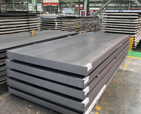
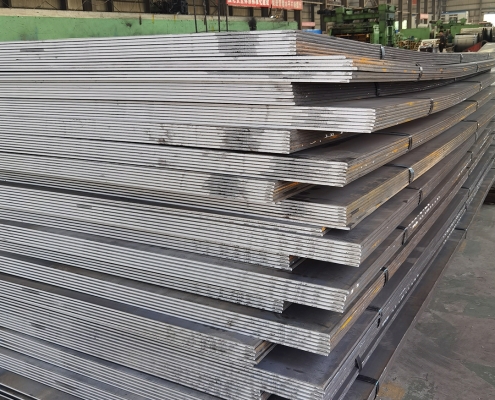
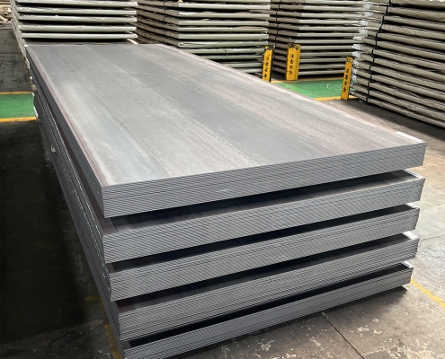
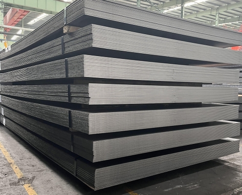
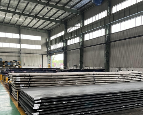
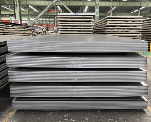
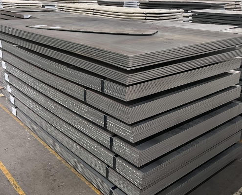
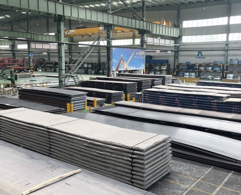
ZAM Coated Steel for Photovoltaic Brackets

Zinc-Aluminum-Magnesium (ZAM) vs Hot-dip galvanizing (HDG)

Définition

What is Zinc-Aluminum-Magnesium (ZAM)?

Zinc-aluminum-magnesium (ZAM) is a high-performance metallic coating applied to steel designed to offer superior corrosion resistance, durability, and heat resistance compared to traditional galvanizing (zinc-only coatings). The coating combines zinc (Zn), aluminum (Al), and magnesium (Mg), which provides unique advantages in various applications.

ZAM Coating

ZAM Coating

What is Hot-dip galvanizing? (HDG)?

Hot-dip galvanization is a form of galvanization. It is the process of coating iron and steel with zinc, which alloys with the base metal surface when immersing the metal in a bath of molten zinc at a temperature of around 450 °C (842 °F). When exposed to the atmosphere, the pure zinc (Zn) reacts with oxygen (O2) to form zinc oxide (ZnO), which further reacts with carbon dioxide (CO2) to form zinc carbonate (ZnCO3), a usually dull grey, fairly strong material that protects the steel underneath from further corrosion in many circumstances.

Hot-dip Galvanizing

Hot-dip Galvanizing

Main Differences: Zinc-Aluminum-Magnesium (ZAM) vs Hot-dip galvanizing (HDG)

The comparison between zinc-aluminum-magnesium (ZAM) et hot-dip galvanizing (HDG) revolves around their coating composition, corrosion resistance, applications, cost, et environmental impact. Below is a detailed comparison to help understand their differences:

1. Coating Composition

Zinc-Aluminum-Magnesium (ZAM):
ZAM coatings are made of a combination of zinc (Zn), aluminum (Al), et magnesium (Mg). Typically, the composition is about 80-90% Zinc, 5-11% Aluminum, et 1-3% Magnesium. Including aluminum and magnesium gives the coating superior properties compared to zinc alone.

Hot-Dip Galvanizing (HDG):
HDG involves immersing steel into a molten bath of zinc (Zn) to form a protective zinc coating. The coating consists almost entirely of zinc, with small amounts of iron from the substrate, forming a zinc-iron alloy layer.

2. Résistance à la corrosion

Zinc-Aluminum-Magnesium (ZAM):
Superior corrosion resistance compared to hot-dip galvanized steel. Adding aluminum increases the coating’s resistance to high temperatures and oxidation, while magnesium improves its resistance to corrosion in harsh environments like coastal, industrial, and chemical settings. ZAM has self-healing properties—if the coating is damaged, the magnesium component reacts with moisture to help prevent further corrosion.

Hot-Dip Galvanizing (HDG):
It provides good corrosion resistance but not as high as ZAM, especially in aggressive environments. The zinc coating is sacrificial, meaning it corrodes first to protect the underlying steel, but its effectiveness can be limited in humid, salty, ou chemical environments. HDG does not have the advanced self-healing properties that ZAM offers.

3. Durability and Longevity

Zinc-Aluminum-Magnesium (ZAM):
ZAM-coated products can last 2 to 4 times longer than traditional galvanized steel in harsh environments (e.g., coastal areas, chemical plants, etc.). The coating’s enhanced resistance to environmental factors contributes to a longer service life.

Hot-Dip Galvanizing (HDG):
The lifespan of HDG products is good but generally shorter than ZAM, particularly in extreme conditions. HDG can last for many years in less corrosive environments (e.g., mild climates), but its protection may degrade faster in severe environments.

4. Applications

Zinc-Aluminum-Magnesium (ZAM):
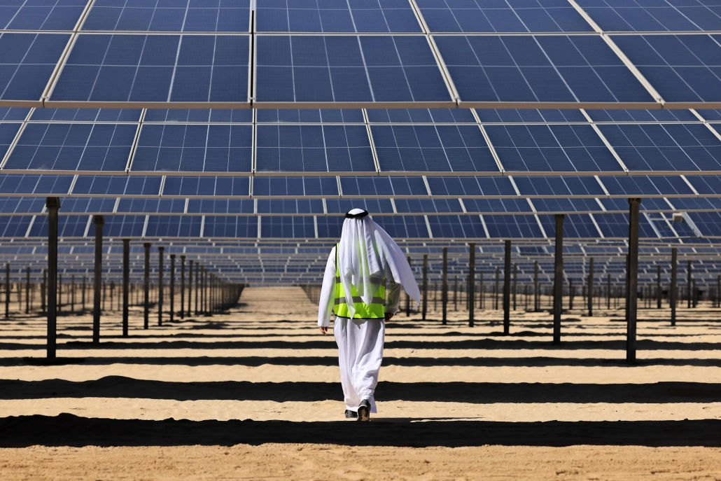
Ideal for environnements difficiles such as Coastal areas (where saltwater exposure is high), Chemical and industrial environments (where exposure to aggressive substances is every day), Solar panel mounts (due to its superior durability), Heavy-duty industrial applications (e.g., agricultural and mining equipment, steel structures exposed to extreme weather conditions).

Hot-Dip Galvanizing (HDG):
It is commonly used in general construction, automotive industries, outdoor infrastructure, et agricultural applications. It is suitable for general-purpose corrosion protection in outdoor conditions but not recommended for extreme or coastal environments.

5. Cost

Zinc-Aluminum-Magnesium (ZAM):
It is more expensive than traditional hot-dip galvanizing due to the inclusion of aluminum and magnesium and the more advanced coating process. The longer lifespan and lower maintenance costs in harsh environments often justify the higher initial cost.

Hot-Dip Galvanizing (HDG):
It is cheaper than ZAM, making it more suitable for projects where cost-efficiency is a priority and the environment is less aggressive. The relatively lower cost makes it ideal for large-scale production.

6. Environmental Impact

Zinc-Aluminum-Magnesium (ZAM):
The production of ZAM coatings is more environmentally friendly than hot-dip galvanizing, as it involves lower emissions of harmful gases and waste materials. The production process for ZAM generally generates less waste et fewer harmful emissions compared to traditional galvanizing methods.

Hot-Dip Galvanizing (HDG):
It is more environmentally intensive than ZAM, producing more waste gases and wastewater. However, modern improvements in the HDG process have aimed to reduce the environmental footprint, though it remains higher than ZAM.

7. Aesthetic Appearance

Zinc-Aluminum-Magnesium (ZAM):
ZAM has a matte gray finish with a smoother, more uniform appearance. This appearance can be more desirable in specific applications like architectural structures or solar panel mounts.

Hot-Dip Galvanizing (HDG):
HDG often has a shiny or dull metallic finish, depending on the thickness of the coating. While durable, its aesthetic appearance may be less appealing than ZAM’s, especially if the finish is uneven.

8. Ease of Processing and Welding

Zinc-Aluminum-Magnesium (ZAM):
ZAM coatings can be more challenging to process, weld, et paint than traditional galvanized steel, creating issues in some applications.

Hot-Dip Galvanizing (HDG):
HDG products are easier to weld and process than ZAM. However, the zinc coating can make welding and cutting more difficult due to zinc fumes, and special precautions may be required.

Summary Comparison Table: Zinc-Aluminum-Magnesium (ZAM) vs Hot-dip Galvanizing (HDG)

Fonctionnalité Zinc-Aluminum-Magnesium (ZAM) Hot-Dip Galvanizing (HDG)
Coating Composition Zinc, Aluminum, Magnesium Zinc (with some iron from the substrate)
Résistance à la corrosion Superior, especially in harsh environments Good, but less effective in aggressive settings
Durability and Longevity 2-4 times longer than HDG in extreme environments Moderate lifespan, shorter in harsh conditions
Applications Coastal areas, chemical environments, heavy-duty General outdoor infrastructure, agriculture
Coût Higher initial cost Lower initial cost
Impact environnemental Lower emissions and waste Higher emissions and waste
Aesthetic Appearance Matte gray, smoother finish Shiny or dull metallic finish
Ease of Processing It can be more challenging, especially with welding It is more straightforward to process and weld

Conclusion

ZAM is the best choice for extreme environments where superior corrosion resistance and durability are needed. Its long-term performance can justify the higher upfront cost.

HDG remains the go-to solution for general corrosion protection in less aggressive environments, providing a cost-effective and widely available option for most standard applications.

Pipeline vs Piping

Onshore vs Offshore Pipeline and Piping

Introduction

In the realm of energy transportation, the distinction between onshore and offshore pipelines and piping systems plays a crucial role in the efficiency, safety, and environmental impact of resource extraction and distribution. Onshore pipelines, typically situated on land, are designed to transport oil, gas, and other fluids over varying distances, benefiting from relatively more straightforward access for maintenance and monitoring. Conversely, offshore pipelines, laid on the seabed or suspended in water, present unique engineering challenges due to harsh marine conditions and logistical complexities. Understanding the Onshore vs Offshore Pipeline and Piping in design, construction, and operational considerations between these two types of pipelines is essential for optimizing infrastructure development and ensuring sustainable practices in the energy sector.

Definition: Onshore vs Offshore Pipeline and Piping

What is Pipeline?

Pipeline is a long series of pipes, usually of large diameter, running underground, aboveground and underwater, such as a submarine pipeline, and equipped with fittings, such as valves and pumps, to control the flow of large quantities of fluid over long distances. Pipelines have large diameters, making it easy to transport liquids or gases in bulk from one place to another, sometimes for thousands of miles.

Pipeline

Pipeline

What is Piping?

Tuyauterie is a system of pipes used to convey fluids (liquids and gases) from one location to another within the designated boundaries or spaces of petrochemical plants, power plants, refineries, etc. It is also equipped with valves and fittings to control the flow of fluids from one facility to another as needed, but only within the plant’s designated boundaries. Never skip these essential topics when taking an online course on piping engineering. Piping diameters range from 1/2 inch to 80 inches, depending on the facility’s design requirements for fluid transportation, usually from one facility to another within the facility’s boundaries.

Tuyauterie

Tuyauterie

What is Onshore Pipeline?

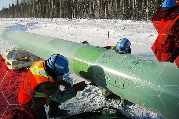
Onshore pipelines refer to networks of pipelines and related equipment used to transport fluids such as oil, natural gas, water, and chemicals in a land environment. These pipelines are integral to long-distance oil and gas transportation from oil fields to refineries, from natural gas wells to gas stations, and from crude oil and refined oil tank farms, chemical tank farms, LNG tank farms, and aircraft refueling pipeline operations.

Onshore Pipeline

Onshore Pipeline

What is Offshore Pipeline?

Offshore pipelines refer to the network of pipes and related equipment used to transport fluids such as oil, gas, water, and chemicals in an offshore environment. These pipelines are integral to operating offshore oil rigs, platforms and floating production storage and offloading units (FPSOs). The unique conditions of the offshore environment, such as high salinity, extreme temperatures, and strong currents, present significant challenges to the design and maintenance of these systems.

Offshore Pipeline

Offshore Pipeline

Main Differences: Onshore vs Offshore Pipeline and Piping

Comparison Table: Onshore vs Offshore Pipeline and Piping

spécification À terre En mer
Pipeline Tuyauterie Pipeline Tuyauterie
Codes de conception – ASME B31.4: Pipeline Transportation Systems for Liquids and Slurries
– ASME B31.8: Gas Transmission and Distribution Piping Systems
ASME B31.3: Process Piping – DNVGL-ST-F101: Submarine pipeline systems
– API RP 1111: Design, Construction, Operation, and Maintenance of Offshore Hydrocarbon Pipelines (Limit state design)
ASME B31.3: Process Piping
Portée Outside plant boundary
(Villages, fields, rivers, canals, railways, highways, cities, deserts, forests, hills, etc.)
Within plant boundary Outside plant boundary Within plant boundary
Type of pipe API Spec 5L: Specification for Line pipes – ASTM
– BS
– API 5L
API Spec 5L: Specification for Line pipes
– DNVGL-ST-F101: Submarine Pipeline Systems
Normes ASTM
Vannes – API 6D: Specification for Pipeline and Piping Valves
– Full Bore (FB) Ball Valves are used for pigs.
– BS
– API Standard
– Full bore (FB) and Reduced bore (RB)
– Full bore Valves: for smooth passage of intelligent pigs
– API 6D SS: Specification on Subsea Pipeline Valves
– RB valves
– BS/API standards
Soudage – API Std. 1104: Welding of Pipelines and Related Facilities
– Type of welding: Automatic / Semi-Automatic/ Manual
– ASME Sec. IX: Standard for Welding and Brazing Procedures, Welders, Brazers and Welding and Brazing Operators
– Type of welding: Manual (mostly)
– API Std. 1104: Welding of Pipelines and Related Facilities
– Mostly automatic welding on pipelay barge.
– ASME Sec. IX: Standard for Welding and Brazing Procedures, Welders, Brazers and Welding and Brazing Operators
– Manual welding at the fabrication yard.
Weld joint inspection (NDT requirements) 100% by Automatic UT or RT (by using X-Ray) 5% to 100%
(mostly by using gamma rays)
100% by Automatic UT From 10% to 100% as required
Analyses – Wall Thickness Analysis
– Elastic Bend Radius Analysis
– Stability Analysis for Water Bodies/ Marshy Areas
– Horizontal directional drilling design analysis
– Railroad/ Highway Crossing Analysis
– Casing Pipe Analysis for Crossings
– Seismic Analysis
– Piping wall thickness calculation
– Piping Stress Analysis
Static Analysis
Dynamic Analysis
Wind Analysis
Flange Leakage Analysis
Seismic Analysis
– Wall thickness Analysis
– On-bottom Stability
– Span Analysis
– Global Buckling – Lateral and Upheaval
– Pipeline Expansion Analysis
– Riser Design (Span, Stress & Flexibility Analysis)
– Riser Clamp Design
– Pipeline Crossing Design and Analysis
– Deck piping stress analysis
Installation Buried (mostly) Above ground/On rack/slippers/T-postal etc. Subsea (in water on the seabed or buried in the seabed) Deck Platform Piping
(similar to plant)
Special Installations – Across rivers
– Horizontal Directional Drilling (HDD) method
– Micro-tunnelling method
– Across road/ rail/ highway
– Auger boring/ jacking boring method
– Shallow HDD
– Ghats/ Hills
– Modular installations
– Finning
– Studding
– Jacketing
– Spooling inside warehouse
– U/G piping for cooling water
– S-lay Method (for shallow water installation)
– J-Lay Method (for deep water installation)
– Shore pull/ barge pull near Land Fall Point (LFP)
Along with the deck structure
Special Equipment – Sectionalizing Valves (Remote operated)
– Insulating Joints
– Scraper Launcher/ Receiver
– Stem Extended Valves (for buried valves)
– Flow Tee
– Long Radius bends (R=6D)
– Cold field bends (R = 30D or 40D)
– Expansion Joints
– Motor Operator Valves (MOV)
– Cryogenic Valves
– Springs
– Subsea Isolation Valve (SSIV)
– LR Bends
– Flow tee
– Pipeline End Manifold (PLEM)
– Single Point Mooring (SPM) system
– Submarine hoses
– Floating hoses
– Cables and umbilical installation
– Piggy-back pipelines
Non applicable
Survey – Topographical Survey
(all along the pipeline route)
– Geotechnical investigation
(all along the pipeline route)
– Soil resistivity survey
(all along the pipeline route)
– Hydrological Survey for water bodies (for scour depth calculation)
– Cadastral Survey (for RoU acquisition)
– Wind profile from meteorology
– Seismic study of plot
– Geophysical survey/ Bathymetric Survey by using side scan sonar, sub-bottom profiler, and echo-sounder
– Met-Ocean data collection
– Geotechnical data of the pipeline route
Non applicable
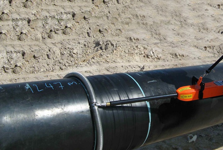
Corrosion Protection Coating Three Layer Polyethylene (3LPE) coating
Three Layer Polypropylene (3LPP) coating
Fusion bonded epoxy (FBE) coating
– Coal tar enamel (CTE) Coating
Painting Coatings such as:
– Coal Tar Enamel Coating (CTE)
Three-layer polyethylene coating (3LPE)
Three-layer polypropylene coating (3LPP)
– Double-layer fusion bonded epoxy coating (2FBE)
Painting
Cathodic Protection System – Impressed Current Cathodic Protection (ICCP) system
– Sacrificial Anode (limited locations)
Not applicable Sacrificial Anodic Cathodic Protection (SACP) system Non applicable
Hydrostatic testing – Gauge Plate run of 95% of the ID of the highest pipe thickness
– Test Pressure
Minimum: 1.25 times of Design Pressure (for liquid pipelines)
1.25 to 1.5 times of Design Pressure (for gas pipelines)
Maximum: Pressure equivalent to Hoop stress of 95% of SMYS of pipe material
– Hold period: 24 hours
– No gauge plate run is done. Generally, cardboard blasting is done to clean the piping.
– Test Pressure
Minimum: 1.5 × Design Pressure × Temperature Factor
Maximum: Based on line schedule
– Hold period: 2 – 6 hours
– Gauge Plate run of 95% of the ID of the highest pipeline thickness.
– Test Pressure
Minimum: 1.25 times x Design Pressure
– Hold period: 24 hours
– No gauging is done.
– Test Pressure
Maximum: As per line schedule
– Hold period: 2 hours
Preservation – Preservation of pipeline with corrosion-inhibited water or by filling of inert gas (N2) Not applicable
Pigging Intelligent Pigging Not applicable Compliant Not applicable
Machines/Equipment required for installation – Trencher
– Backhoe/ Excavator
– Side Boom
– Cold field bending machine
– Holiday Detection Machines
– Pneumatic/ Hydraulic Internal Clamps
Crane/ Hydra – Pipelay Barge
– Derrick Barge
– Diving support vessel
– Dynamic Positioning (DP) barge (for deepwater)
Pre-fabricated deck piping

Conclusion: Onshore vs Offshore Pipeline and Piping

In summary, Onshore pipelines are usually buried or erected on land to transport oil, natural gas, drinking water, sewage, seawater, slurry, etc. Onshore piping is typically erected in petrochemical plants, power plants, refineries, fire protection systems, water treatment systems, etc., while Offshore pipelines are buried on the seabed. Offshore piping typically consists of transmission and structural support pipeline systems on offshore drilling platforms. Special offshore equipment includes underwater isolation valves, tees, and submarine hoses. Offshore surveys include geophysics, bathymetry, and ocean data collection, while onshore surveys focus on topographic and geotechnical engineering studies.

L80-9Cr vs L80-13Cr

L80-9Cr vs L80-13Cr: Something You Need to Know

Choosing the proper casing and tubing materials can ensure safety and efficiency in oil and gas drilling and exploration. L80-9Cr and L80-13Cr are two alloy steel grades commonly used in petroleum casing and tubing. Each grade has unique characteristics and applications. L80-9Cr vs L80-13Cr, this article will delve into the difference between these materials to help you make an informed decision.

1. Overview of L80 Grade

L80 is an alloy steel used in the oil and gas sector. It is known for its good strength and corrosion resistance. It is typically employed in high-temperature and high-pressure environments and is suitable for both oil and gas production.

1.1 L80-9Cr

Composition: Contains 9% chromium, enhancing the material’s oxidation resistance at high temperatures.
Caractéristiques:
Corrosion Resistance: It performs well in CO2 environments, making it suitable for acidic gas pipelines.
Mechanical Strength: Provides good strength and is suitable for high-temperature operations.
Applications: Commonly used in high-temperature gas pipelines in oil fields.

1.2 L80-13Cr

Composition: Contains 13% chromium, offering higher corrosion resistance.
Caractéristiques:
Corrosion Resistance: Exhibits superior performance in environments with H2S and CO2, suitable for extreme conditions.
Mechanical Strength: Offers higher strength and is ideal for complex operational environments.
Applications: Used in high-corrosion environments and deep well operations.

L80-9Cr vs L80-13Cr

L80-9Cr and L80-13Cr Casing and Tubing in Oil and Gas Drilling and Exploration

2. Comparison: L80-9Cr vs L80-13Cr

2.1 Chemical Composition

Standard Grade C Si Mn P. S Cr Mo Ni Cu
API5CT L80-9Cr ≤ 0,15 ≤ 1.00 0.30-0.60 ≤ 0,020 ≤ 0,010 8.00-10.00 0.90-1.10 ≤ 0.50 ≤ 0,25
L80-13Cr 0.15-0.22 ≤ 1.00 0.25-1.00 ≤ 0,020 ≤ 0,010 12.00-14.00 ≤ 0.50 ≤ 0,25

2.2 Propriétés mécaniques

Standard Grade Yield Strength (Mpa) Résistance à la traction (MPa) Allongement (%) Hardness max
min. max. min. min. CRH HBW
API5CT L80-9Cr 552 655 655 API5CT
Table C.7
23 241
L80-13Cr 552 655 655 23 241

2.3 Impact Test

Standard Grade Sharpy Impact Energy (J)
Coupling Corps de tuyau
API5CT L80-9Cr L-10-40-0 T-10-20-0 L-10-27-0 T-10-14-0
L80-13Cr L-10-40-0 T-10-20-0 L-10-27-0 T-10-14-0

2.4 Corrosion Resistance

L80-9Cr: The 9% chromium content provides moderate corrosion resistance, suitable for environments with low to moderate concentrations of H₂S (hydrogen sulfide) or CO₂ (carbon dioxide), typically seen in less aggressive environments.

L80-13Cr: The 13% chromium content provides enhanced resistance to sour service (i.e., environments with high levels of H₂S) and high CO₂ environments. It’s better for harsher conditions like deep wells or offshore drilling.

2.5 Temperature and Sour Service

L80-9Cr: Generally suitable for moderate-temperature environments.

L80-13Cr: Can withstand higher temperatures and is better equipped for sour service conditions with high concentrations of H₂S or CO₂.

2.6 Cost

L80-9Cr: Due to its lower chromium content, L80-9Cr is less expensive than L80-13Cr. If the environment is not highly corrosive or sour, L80-9Cr could be a more cost-effective option.

L80-13Cr: More expensive but provides superior resistance in harsh conditions, potentially reducing maintenance costs or failures over time.

2.7 Applications

L80-9Cr: Suitable in wells with moderate temperature, pressure, and sour gas conditions. Often used in conventional oil and gas wells or less aggressive service environments.

L80-13Cr: Ideal for high-pressure wells with harsh environmental conditions, particularly in sour gas service, deep wells, or offshore oil & gas operations where high corrosion resistance is critical.

Éoliennes offshore

Profilés creux circulaires structurels pour éoliennes terrestres et offshore

Alors que la demande en énergie renouvelable ne cesse d'augmenter à l'échelle mondiale, l'énergie éolienne offshore s'est imposée comme une solution essentielle. Cet article examine l'importance des sections creuses circulaires structurelles (CHS) utilisées dans les structures porteuses des éoliennes offshore, en explorant leur conception, leurs propriétés matérielles et leurs applications.

1. Comprendre les sections creuses circulaires structurelles

Profilés creux circulaires structurels Les tubes cylindriques sont des tubes creux au centre. Ces sections jouent un rôle crucial dans les structures de support des éoliennes offshore, qui sont principalement conçues pour supporter le poids de l'éolienne et résister aux pressions environnementales externes.

2. Propriétés matérielles des sections creuses circulaires structurelles

Acier au carbone : S355MH, S355MLH, S420MH, S420MLH, S460MH, S460MLH, S460QH, S460QLH, S620QH, S620QLH, S690QH, S690QLH

3. Considérations relatives à la conception

Lors de la conception des structures de support des éoliennes offshore, plusieurs facteurs doivent être pris en compte :
Charge éolienne : les turbines subissent des charges dynamiques dues au vent pendant leur fonctionnement, ce qui nécessite une conception qui garantit la stabilité structurelle.
Impact des vagues : Les vagues dans les environnements marins exercent une pression supplémentaire sur les structures, nécessitant des calculs et des ajustements de conception minutieux.
Protection contre la corrosion : Étant donné la nature corrosive de l’eau de mer, l’utilisation de revêtements protecteurs ou de matériaux résistants à la corrosion est essentielle pour prolonger la durée de vie de la structure.

4. Avantages de l'utilisation de sections creuses circulaires

L'utilisation de sections creuses circulaires dans les structures de support offre plusieurs avantages :
Haute résistance à la compression : la section transversale circulaire permet une répartition uniforme de la pression, améliorant ainsi la stabilité globale.
Léger : Comparés à d’autres formes, les tubes circulaires offrent une résistance similaire avec un poids réduit, facilitant le transport et l’installation.
Facilité de construction : La simplicité de connexion et de soudage des tubes circulaires augmente l'efficacité de la construction.

5. Questions fréquemment posées

Q: Quel matériau choisir pour les profilés creux circulaires structurels ?
UN: Le choix du matériau dépend des conditions environnementales spécifiques, du budget et des exigences de conception. L'acier au carbone convient à la plupart des applications, mais dans les environnements hautement corrosifs, l'acier inoxydable ou l'acier allié peuvent être plus appropriés.

Q: Comment assurer la durabilité des profilés creux circulaires structurels ?
UN: Des inspections et un entretien réguliers sont essentiels pour garantir la durabilité des structures. De plus, le choix de revêtements et de matériaux de protection appropriés peut prolonger considérablement la durée de vie des structures.

6. Conclusion

Les sections creuses circulaires structurelles sont indispensables dans les structures porteuses des éoliennes offshore. Grâce à une conception et une sélection minutieuses des matériaux, les éoliennes peuvent être améliorées en termes de stabilité et de durabilité, favorisant ainsi le développement des énergies renouvelables.

Pour plus d'informations ou pour obtenir de l'aide concernant les sections creuses structurelles pour les structures d'éoliennes terrestres et offshore, n'hésitez pas à nous contacter au [email protected].

Production d'acier brut

Production d'acier brut en septembre 2024

En septembre 2024, la production mondiale d'acier brut des 71 pays déclarants auprès de la World Steel Association (acier mondial) était de 143,6 millions de tonnes (Mt), soit une baisse de 4,71 TP3T par rapport à septembre 2023.

production d'acier brut

production d'acier brut

Production d'acier brut par région

L'Afrique a produit 1,9 Mt en septembre 2024, en hausse de 2,6% par rapport à septembre 2023. L'Asie et l'Océanie ont produit 105,3 Mt, en baisse de 5,0%. L'UE (27) a produit 10,5 Mt, en hausse de 0,3%. L'Europe, Autres a produit 3,6 Mt, en hausse de 4,1%. Le Moyen-Orient a produit 3,5 Mt, en baisse de 23,0%. L'Amérique du Nord a produit 8,6 Mt, en baisse de 3,4%. La Russie et les autres pays de la CEI + l'Ukraine ont produit 6,8 Mt, en baisse de 7,6%. L'Amérique du Sud a produit 3,5 Mt, en hausse de 3,3%.

Tableau 1. Production d'acier brut par région

Région Septembre 2024 (Mt) % change le 24/23 septembre Jan-Sep 2024 (Mt) % change 24/23/20 janvier-septembre
Afrique 1.9 2.6 16.6 2.3
Asie et Océanie 105.3 -5 1,032.00 -2.5
UE (27) 10.5 0.3 97.8 1.5
Europe, Autre 3.6 4.1 33.1 7.8
Moyen-Orient 3.5 -23 38.4 -1.5
Amérique du Nord 8.6 -3.4 80 -3.9
Russie et autres pays de la CEI + Ukraine 6.8 -7.6 64.9 -2.5
Amérique du Sud 3.5 3.3 31.4 0
Total 71 pays 143.6 -4.7 1,394.10 -1.9

Les 71 pays inclus dans ce tableau représentaient environ 98% de la production mondiale totale d’acier brut en 2023.

Régions et pays couverts par le tableau :

  • Afrique: Algérie, Egypte, Libye, Maroc, Afrique du Sud, Tunisie
  • Asie et Océanie : Australie, Chine, Inde, Japon, Mongolie, Nouvelle-Zélande, Pakistan, Corée du Sud, Taïwan (Chine), Thaïlande, Vietnam
  • Union européenne (27) : Autriche, Belgique, Bulgarie, Croatie, Tchéquie, Finlande, France, Allemagne, Grèce, Hongrie, Italie, Luxembourg, Pays-Bas, Pologne, Portugal, Roumanie, Slovaquie, Slovénie, Espagne, Suède
  • Europe, Autre : Macédoine, Norvège, Serbie, Turquie, Royaume-Uni
  • Moyen-Orient: Bahreïn, Iran, Irak, Jordanie, Koweït, Oman, Qatar, Arabie saoudite, Émirats arabes unis, Yémen
  • Amérique du Nord: Canada, Cuba, El Salvador, Guatemala, Mexique, États-Unis
  • Russie et autres pays de la CEI + Ukraine : Biélorussie, Kazakhstan, Russie, Ukraine
  • Amérique du Sud: Argentine, Brésil, Chili, Colombie, Équateur, Paraguay, Pérou, Uruguay, Venezuela

Top 10 des pays producteurs d'acier

La Chine a produit 77,1 Mt en septembre 2024, en baisse de 6,1% par rapport à septembre 2023. L'Inde a produit 11,7 Mt, en baisse de 0,2%. Le Japon a produit 6,6 Mt, en baisse de 5,8%. Les États-Unis ont produit 6,7 Mt, en hausse de 1,2%. La Russie aurait produit 5,6 Mt, en baisse de 10,3%. La Corée du Sud a produit 5,5 Mt, en hausse de 1,3%. L'Allemagne a produit 3,0 Mt, en hausse de 4,3%. La Turquie a produit 3,1 Mt, en hausse de 6,5%. Le Brésil a produit 2,8 Mt, en hausse de 9,9%. L'Iran aurait produit 1,5 Mt, en baisse de 41,2%.

Tableau 2. Les 10 premiers pays producteurs d'acier

Région  Septembre 2024 (Mt) % change le 24/23 septembre Jan-Sep 2024 (Mt) % change 24/23/20 janvier-septembre
Chine 77.1 -6.1 768.5 -3.6
Inde 11.7 -0.2 110.3 5.8
Japon 6.6 -5.8 63.3 -3.2
États-Unis 6.7 1.2 60.3 -1.6
Russie 5.6 e -10.3 54 -5.5
Corée du Sud 5.5 1.3 48.1 -4.6
Allemagne 3 4.3 28.4 4
Turquie 3.1 6.5 27.9 13.8
Brésil 2.8 9.9 25.2 4.4
L'Iran 1,5 e -41.2 21.3 -3.1

e – estimation. Le classement des 10 premiers pays producteurs est basé sur les données cumulées depuis le début de l’année.

API 5L et ISO 3183

Connaître les différences : API 5L vs ISO 3183

Les normes ISO 3183 et API 5L concernent les tubes en acier, principalement destinés à être utilisés dans les secteurs du pétrole, du gaz et d'autres transports de fluides. Bien qu'il existe un chevauchement important entre ces deux normes, API 5L et ISO 3183, des différences clés existent dans leur champ d'application, leur application et les organismes qui les soutiennent.

1. Organismes émetteurs : API 5L vs ISO 3183

API 5L : Émise par l'American Petroleum Institute (API), cette norme est principalement utilisée dans l'industrie pétrolière et gazière. Elle détaille les exigences techniques applicables aux conduites en acier transportant du pétrole, du gaz et de l'eau.
ISO 3183 : Publiée par l'Organisation internationale de normalisation (ISO), cette norme est reconnue internationalement et utilisée dans le monde entier pour les tubes en acier dans le secteur du transport du pétrole et du gaz.

2. Champ d'application : API 5L vs ISO 3183

API 5L : concerne les tuyaux en acier destinés au transport du pétrole, du gaz naturel et d'autres fluides sous haute pression. Elle est largement utilisée en Amérique du Nord, notamment aux États-Unis.
ISO 3183 : Cette norme se concentre principalement sur la conception, la fabrication et le contrôle de la qualité des tubes en acier utilisés dans les oléoducs et gazoducs, mais son utilisation est plus internationale et applicable dans divers pays du monde.

3. Principales différences : API 5L et ISO 3183

Focus géographique et marché :

L'API 5L est davantage adaptée au marché nord-américain (en particulier aux États-Unis), tandis que la norme ISO 3183 est applicable à l'échelle internationale et utilisée dans de nombreux pays à travers le monde.

Nuances d'acier et exigences :

L'API 5L définit des nuances d'acier telles que L175, L210, L245, etc., où le nombre représente la limite d'élasticité minimale en mégapascals (MPa).
La norme ISO 3183 définit également des catégories similaires mais avec des exigences plus détaillées concernant les propriétés des matériaux, les processus de fabrication et les protocoles d'inspection, en accord avec les pratiques internationales de l'industrie.
Spécifications supplémentaires :
L'API 5L met l'accent sur le contrôle qualité, la certification et les exigences de production, tandis que la norme ISO 3183 couvre un champ d'application plus large, en tenant compte du commerce international, et fournit des spécifications pour différentes conditions, notamment la température, l'environnement et les exigences mécaniques spécifiques.

4. Exigences techniques : API 5L vs ISO 3183

La norme API 5L spécifie les propriétés des matériaux, les procédés de fabrication, les dimensions, les méthodes d'essai et le contrôle qualité des tubes en acier. Elle définit les nuances d'acier de L (faible résistance) à X (résistance plus élevée), telles que X42, X60 et X70.
La norme ISO 3183 couvre des aspects similaires de la fabrication de tubes en acier, notamment la qualité des matériaux, le traitement thermique, le traitement de surface et les extrémités des tubes. Elle fournit également des spécifications détaillées sur la pression de conception des canalisations, les considérations environnementales et divers accessoires de canalisations.

5. Comparaison des qualités de tubes : API 5L et ISO 3183

API 5L : les grades vont des grades L (faible limite d'élasticité) aux grades X (limite d'élasticité plus élevée). Par exemple, X60 fait référence aux tuyaux ayant une limite d'élasticité de 60 000 psi (environ 413 MPa).
ISO 3183 : elle utilise un système de classement similaire mais peut inclure des classifications et des conditions plus détaillées. Elle garantit également l'alignement avec les pratiques opérationnelles et de conception des pipelines à l'échelle mondiale.

6. Compatibilité entre les normes :

Dans de nombreux cas, les normes API 5L et ISO 3183 sont compatibles, ce qui signifie qu'un tube en acier qui répond aux exigences de l'API 5L répondra généralement également aux exigences de l'ISO 3183 et vice versa. Cependant, des projets de pipeline spécifiques peuvent adhérer à une norme plutôt qu'à une autre en fonction de l'emplacement, des préférences du client ou des exigences réglementaires.

7. Conclusion :

L'API 5L est plus répandue aux États-Unis et dans les régions voisines. Elle est destinée au secteur des pipelines de pétrole et de gaz, en mettant fortement l'accent sur la production et le contrôle de la qualité.
La norme ISO 3183 est une norme internationale pour les projets internationaux de pipelines de pétrole et de gaz. Ses exigences plus détaillées et harmonisées à l'échelle mondiale garantissent une plus large acceptation sur les marchés internationaux.

Les deux normes sont très similaires en ce qui concerne les spécifications relatives aux matériaux, à la fabrication et aux essais. Cependant, la norme ISO 3183 a tendance à avoir une portée plus large et applicable à l'échelle mondiale, tandis que l'API 5L reste plus spécifique au marché nord-américain. Le choix entre ces normes dépend de la situation géographique du projet de pipeline, des spécifications et des besoins réglementaires.