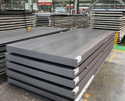
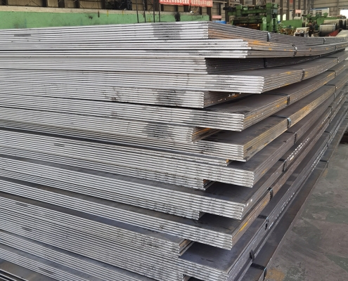
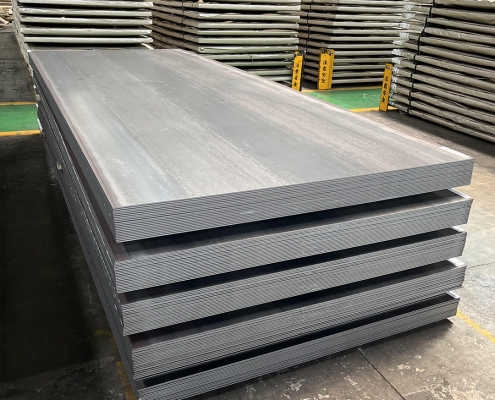
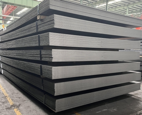
ZAM Coated Steel for Photovoltaic Brackets

Zinc-Aluminum-Magnesium (ZAM) vs Hot-dip galvanizing (HDG)

Definice

What is Zinc-Aluminum-Magnesium (ZAM)?

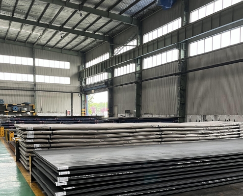
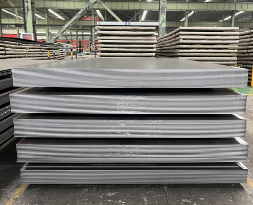
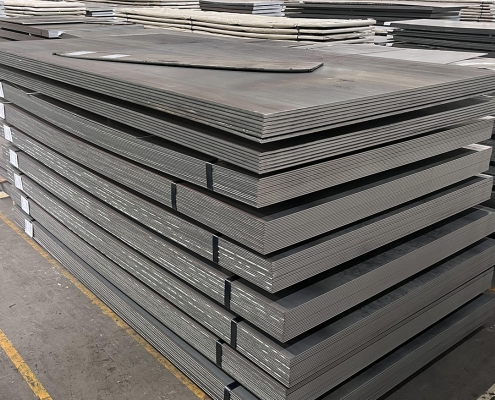
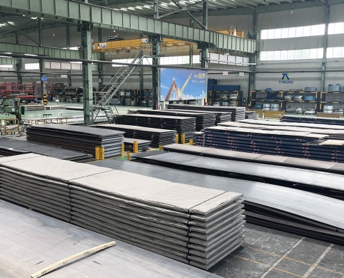
Zinc-aluminum-magnesium (ZAM) is a high-performance metallic coating applied to steel designed to offer superior corrosion resistance, durability, and heat resistance compared to traditional galvanizing (zinc-only coatings). The coating combines zinc (Zn), aluminum (Al), and magnesium (Mg), which provides unique advantages in various applications.

ZAM Coating

ZAM Coating

What is Hot-dip galvanizing? (HDG)?

Hot-dip galvanization is a form of galvanization. It is the process of coating iron and steel with zinc, which alloys with the base metal surface when immersing the metal in a bath of molten zinc at a temperature of around 450 °C (842 °F). When exposed to the atmosphere, the pure zinc (Zn) reacts with oxygen (O2) to form zinc oxide (ZnO), which further reacts with carbon dioxide (CO2) to form zinc carbonate (ZnCO3), a usually dull grey, fairly strong material that protects the steel underneath from further corrosion in many circumstances.

Hot-dip Galvanizing

Hot-dip Galvanizing

Main Differences: Zinc-Aluminum-Magnesium (ZAM) vs Hot-dip galvanizing (HDG)

The comparison between zinc-aluminum-magnesium (ZAM) a hot-dip galvanizing (HDG) revolves around their coating composition, corrosion resistance, applications, cost, a environmental impact. Below is a detailed comparison to help understand their differences:

1. Coating Composition

Zinc-Aluminum-Magnesium (ZAM):
ZAM coatings are made of a combination of zinc (Zn), aluminum (Al), a magnesium (Mg). Typically, the composition is about 80-90% Zinc, 5-11% Aluminum, a 1-3% Magnesium. Including aluminum and magnesium gives the coating superior properties compared to zinc alone.

Hot-Dip Galvanizing (HDG):
HDG involves immersing steel into a molten bath of zinc (Zn) to form a protective zinc coating. The coating consists almost entirely of zinc, with small amounts of iron from the substrate, forming a zinc-iron alloy layer.

2. Odolnost proti korozi

Zinc-Aluminum-Magnesium (ZAM):
Superior corrosion resistance compared to hot-dip galvanized steel. Adding aluminum increases the coating’s resistance to high temperatures and oxidation, while magnesium improves its resistance to corrosion in harsh environments like coastal, industrial, and chemical settings. ZAM has self-healing properties—if the coating is damaged, the magnesium component reacts with moisture to help prevent further corrosion.

Hot-Dip Galvanizing (HDG):
It provides good corrosion resistance but not as high as ZAM, especially in aggressive environments. The zinc coating is sacrificial, meaning it corrodes first to protect the underlying steel, but its effectiveness can be limited in humid, saltynebo chemical environments. HDG does not have the advanced self-healing properties that ZAM offers.

3. Durability and Longevity

Zinc-Aluminum-Magnesium (ZAM):
ZAM-coated products can last 2 to 4 times longer than traditional galvanized steel in harsh environments (e.g., coastal areas, chemical plants, etc.). The coating’s enhanced resistance to environmental factors contributes to a longer service life.

Hot-Dip Galvanizing (HDG):
The lifespan of HDG products is good but generally shorter than ZAM, particularly in extreme conditions. HDG can last for many years in less corrosive environments (e.g., mild climates), but its protection may degrade faster in severe environments.

4. Applications

Zinc-Aluminum-Magnesium (ZAM):
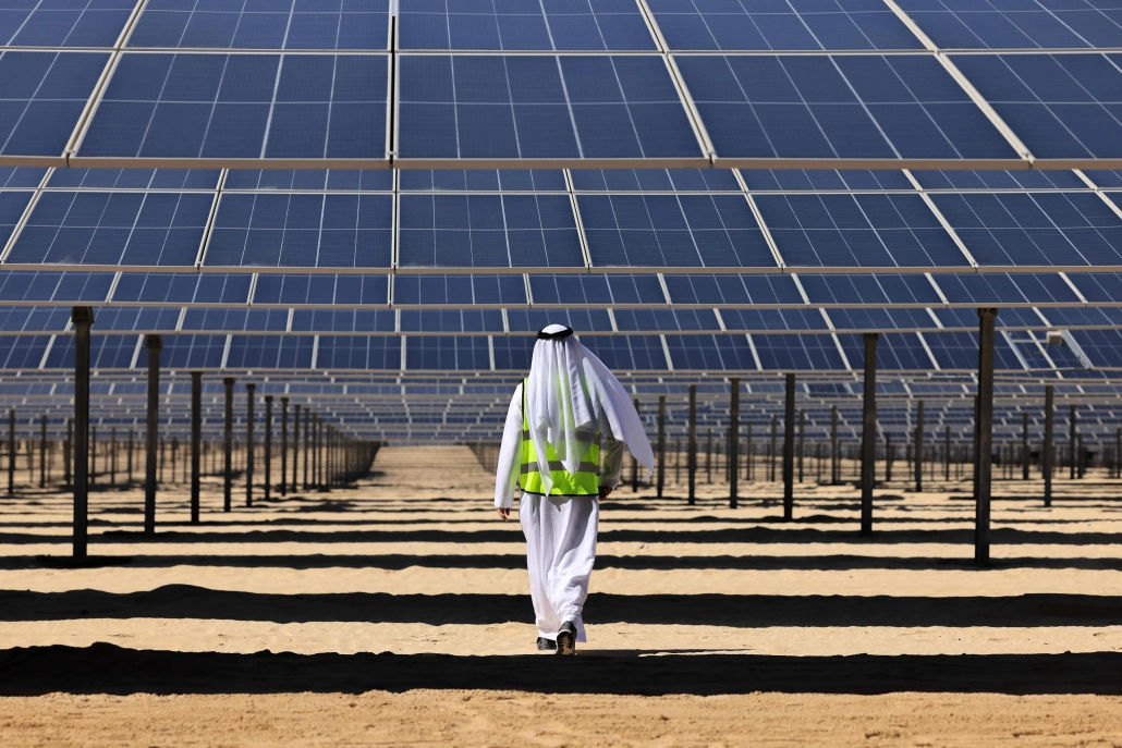
Ideal for drsné prostředí such as Coastal areas (where saltwater exposure is high), Chemical and industrial environments (where exposure to aggressive substances is every day), Solar panel mounts (due to its superior durability), Heavy-duty industrial applications (e.g., agricultural and mining equipment, steel structures exposed to extreme weather conditions).

Hot-Dip Galvanizing (HDG):
It is commonly used in general construction, automotive industries, outdoor infrastructure, a agricultural applications. It is suitable for general-purpose corrosion protection in outdoor conditions but not recommended for extreme or coastal environments.

5. Cost

Zinc-Aluminum-Magnesium (ZAM):
It is more expensive than traditional hot-dip galvanizing due to the inclusion of aluminum and magnesium and the more advanced coating process. The longer lifespan and lower maintenance costs in harsh environments often justify the higher initial cost.

Hot-Dip Galvanizing (HDG):
It is cheaper than ZAM, making it more suitable for projects where cost-efficiency is a priority and the environment is less aggressive. The relatively lower cost makes it ideal for large-scale production.

6. Environmental Impact

Zinc-Aluminum-Magnesium (ZAM):
The production of ZAM coatings is more environmentally friendly than hot-dip galvanizing, as it involves lower emissions of harmful gases and waste materials. The production process for ZAM generally generates less waste a fewer harmful emissions compared to traditional galvanizing methods.

Hot-Dip Galvanizing (HDG):
It is more environmentally intensive than ZAM, producing more waste gases and wastewater. However, modern improvements in the HDG process have aimed to reduce the environmental footprint, though it remains higher than ZAM.

7. Aesthetic Appearance

Zinc-Aluminum-Magnesium (ZAM):
ZAM has a matte gray finish with a smoother, more uniform appearance. This appearance can be more desirable in specific applications like architectural structures or solar panel mounts.

Hot-Dip Galvanizing (HDG):
HDG often has a shiny or dull metallic finish, depending on the thickness of the coating. While durable, its aesthetic appearance may be less appealing than ZAM’s, especially if the finish is uneven.

8. Ease of Processing and Welding

Zinc-Aluminum-Magnesium (ZAM):
ZAM coatings can be more challenging to process, weld, a paint than traditional galvanized steel, creating issues in some applications.

Hot-Dip Galvanizing (HDG):
HDG products are easier to weld and process than ZAM. However, the zinc coating can make welding and cutting more difficult due to zinc fumes, and special precautions may be required.

Summary Comparison Table: Zinc-Aluminum-Magnesium (ZAM) vs Hot-dip Galvanizing (HDG)

Funkce Zinc-Aluminum-Magnesium (ZAM) Hot-Dip Galvanizing (HDG)
Coating Composition Zinc, Aluminum, Magnesium Zinc (with some iron from the substrate)
Odolnost proti korozi Superior, especially in harsh environments Good, but less effective in aggressive settings
Durability and Longevity 2-4 times longer than HDG in extreme environments Moderate lifespan, shorter in harsh conditions
Aplikace Coastal areas, chemical environments, heavy-duty General outdoor infrastructure, agriculture
Náklady Higher initial cost Lower initial cost
Zásah do životního prostředí Lower emissions and waste Higher emissions and waste
Aesthetic Appearance Matte gray, smoother finish Shiny or dull metallic finish
Ease of Processing It can be more challenging, especially with welding It is more straightforward to process and weld

Závěr

ZAM is the best choice for extreme environments where superior corrosion resistance and durability are needed. Its long-term performance can justify the higher upfront cost.

HDG remains the go-to solution for general corrosion protection in less aggressive environments, providing a cost-effective and widely available option for most standard applications.

Pipeline vs Piping

Pobřežní vs pobřežní potrubí a potrubí

Zavedení

In the realm of energy transportation, the distinction between onshore and offshore pipelines and piping systems plays a crucial role in the efficiency, safety, and environmental impact of resource extraction and distribution. Onshore pipelines, typically situated on land, are designed to transport oil, gas, and other fluids over varying distances, benefiting from relatively more straightforward access for maintenance and monitoring. Conversely, offshore pipelines, laid on the seabed or suspended in water, present unique engineering challenges due to harsh marine conditions and logistical complexities. Understanding the Onshore vs Offshore Pipeline and Piping in design, construction, and operational considerations between these two types of pipelines is essential for optimizing infrastructure development and ensuring sustainable practices in the energy sector.

Definition: Onshore vs Offshore Pipeline and Piping

What is Pipeline?

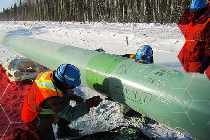
Pipeline is a long series of pipes, usually of large diameter, running underground, aboveground and underwater, such as a submarine pipeline, and equipped with fittings, such as valves and pumps, to control the flow of large quantities of fluid over long distances. Pipelines have large diameters, making it easy to transport liquids or gases in bulk from one place to another, sometimes for thousands of miles.

Pipeline

Pipeline

What is Piping?

Potrubí is a system of pipes used to convey fluids (liquids and gases) from one location to another within the designated boundaries or spaces of petrochemical plants, power plants, refineries, etc. It is also equipped with valves and fittings to control the flow of fluids from one facility to another as needed, but only within the plant’s designated boundaries. Never skip these essential topics when taking an online course on piping engineering. Piping diameters range from 1/2 inch to 80 inches, depending on the facility’s design requirements for fluid transportation, usually from one facility to another within the facility’s boundaries.

Potrubí

Potrubí

What is Onshore Pipeline?

Onshore pipelines refer to networks of pipelines and related equipment used to transport fluids such as oil, natural gas, water, and chemicals in a land environment. These pipelines are integral to long-distance oil and gas transportation from oil fields to refineries, from natural gas wells to gas stations, and from crude oil and refined oil tank farms, chemical tank farms, LNG tank farms, and aircraft refueling pipeline operations.

Onshore Pipeline

Onshore Pipeline

What is Offshore Pipeline?

Offshore pipelines refer to the network of pipes and related equipment used to transport fluids such as oil, gas, water, and chemicals in an offshore environment. These pipelines are integral to operating offshore oil rigs, platforms and floating production storage and offloading units (FPSOs). The unique conditions of the offshore environment, such as high salinity, extreme temperatures, and strong currents, present significant challenges to the design and maintenance of these systems.

Offshore Pipeline

Offshore Pipeline

Main Differences: Onshore vs Offshore Pipeline and Piping

Comparison Table: Onshore vs Offshore Pipeline and Piping

Specifikace Na pevnině Offshore
Pipeline Potrubí Pipeline Potrubí
Kódy designu – ASME B31.4: Pipeline Transportation Systems for Liquids and Slurries
– ASME B31.8: Gas Transmission and Distribution Piping Systems
ASME B31.3: Process Piping – DNVGL-ST-F101: Submarine pipeline systems
– API RP 1111: Design, Construction, Operation, and Maintenance of Offshore Hydrocarbon Pipelines (Limit state design)
ASME B31.3: Process Piping
Rozsah Outside plant boundary
(Villages, fields, rivers, canals, railways, highways, cities, deserts, forests, hills, etc.)
Within plant boundary Outside plant boundary Within plant boundary
Type of pipe API Spec 5L: Specification for Line pipes – ASTM
– BS
– API 5L
API Spec 5L: Specification for Line pipes
– DNVGL-ST-F101: Submarine Pipeline Systems
Normy ASTM
Ventily – API 6D: Specification for Pipeline and Piping Valves
– Full Bore (FB) Ball Valves are used for pigs.
– BS
– API Standard
– Full bore (FB) and Reduced bore (RB)
– Full bore Valves: for smooth passage of intelligent pigs
– API 6D SS: Specification on Subsea Pipeline Valves
– RB valves
– BS/API standards
Svařování – API Std. 1104: Welding of Pipelines and Related Facilities
– Type of welding: Automatic / Semi-Automatic/ Manual
– ASME Sec. IX: Standard for Welding and Brazing Procedures, Welders, Brazers and Welding and Brazing Operators
– Type of welding: Manual (mostly)
– API Std. 1104: Welding of Pipelines and Related Facilities
– Mostly automatic welding on pipelay barge.
– ASME Sec. IX: Standard for Welding and Brazing Procedures, Welders, Brazers and Welding and Brazing Operators
– Manual welding at the fabrication yard.
Weld joint inspection (NDT requirements) 100% by Automatic UT or RT (by using X-Ray) 5% to 100%
(mostly by using gamma rays)
100% by Automatic UT From 10% to 100% as required
Analyses – Wall Thickness Analysis
– Elastic Bend Radius Analysis
– Stability Analysis for Water Bodies/ Marshy Areas
– Horizontal directional drilling design analysis
– Railroad/ Highway Crossing Analysis
– Casing Pipe Analysis for Crossings
– Seismic Analysis
– Piping wall thickness calculation
– Piping Stress Analysis
Static Analysis
Dynamic Analysis
Wind Analysis
Flange Leakage Analysis
Seismic Analysis
– Wall thickness Analysis
– On-bottom Stability
– Span Analysis
– Global Buckling – Lateral and Upheaval
– Pipeline Expansion Analysis
– Riser Design (Span, Stress & Flexibility Analysis)
– Riser Clamp Design
– Pipeline Crossing Design and Analysis
– Deck piping stress analysis
Instalace Buried (mostly) Above ground/On rack/slippers/T-postal etc. Subsea (in water on the seabed or buried in the seabed) Deck Platform Piping
(similar to plant)
Special Installations – Across rivers
– Horizontal Directional Drilling (HDD) method
– Micro-tunnelling method
– Across road/ rail/ highway
– Auger boring/ jacking boring method
– Shallow HDD
– Ghats/ Hills
– Modular installations
– Finning
– Studding
– Jacketing
– Spooling inside warehouse
– U/G piping for cooling water
– S-lay Method (for shallow water installation)
– J-Lay Method (for deep water installation)
– Shore pull/ barge pull near Land Fall Point (LFP)
Along with the deck structure
Special Equipment – Sectionalizing Valves (Remote operated)
– Insulating Joints
– Scraper Launcher/ Receiver
– Stem Extended Valves (for buried valves)
– Flow Tee
– Long Radius bends (R=6D)
– Cold field bends (R = 30D or 40D)
– Expansion Joints
– Motor Operator Valves (MOV)
– Cryogenic Valves
– Springs
– Subsea Isolation Valve (SSIV)
– LR Bends
– Flow tee
– Pipeline End Manifold (PLEM)
– Single Point Mooring (SPM) system
– Submarine hoses
– Floating hoses
– Cables and umbilical installation
– Piggy-back pipelines
Nelze použít
Survey – Topographical Survey
(all along the pipeline route)
– Geotechnical investigation
(all along the pipeline route)
– Soil resistivity survey
(all along the pipeline route)
– Hydrological Survey for water bodies (for scour depth calculation)
– Cadastral Survey (for RoU acquisition)
– Wind profile from meteorology
– Seismic study of plot
– Geophysical survey/ Bathymetric Survey by using side scan sonar, sub-bottom profiler, and echo-sounder
– Met-Ocean data collection
– Geotechnical data of the pipeline route
Nelze použít
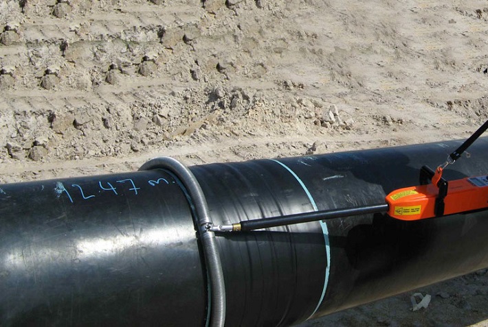
Corrosion Protection Coating Three Layer Polyethylene (3LPE) coating
Three Layer Polypropylene (3LPP) coating
Fusion bonded epoxy (FBE) coating
– Coal tar enamel (CTE) Coating
Painting Coatings such as:
– Coal Tar Enamel Coating (CTE)
Three-layer polyethylene coating (3LPE)
Three-layer polypropylene coating (3LPP)
– Double-layer fusion bonded epoxy coating (2FBE)
Painting
Cathodic Protection System – Impressed Current Cathodic Protection (ICCP) system
– Sacrificial Anode (limited locations)
Not applicable Sacrificial Anodic Cathodic Protection (SACP) system Nelze použít
Hydrostatic testing – Gauge Plate run of 95% of the ID of the highest pipe thickness
– Test Pressure
Minimum: 1.25 times of Design Pressure (for liquid pipelines)
1.25 to 1.5 times of Design Pressure (for gas pipelines)
Maximum: Pressure equivalent to Hoop stress of 95% of SMYS of pipe material
– Hold period: 24 hours
– No gauge plate run is done. Generally, cardboard blasting is done to clean the piping.
– Test Pressure
Minimum: 1.5 × Design Pressure × Temperature Factor
Maximum: Based on line schedule
– Hold period: 2 – 6 hours
– Gauge Plate run of 95% of the ID of the highest pipeline thickness.
– Test Pressure
Minimum: 1.25 times x Design Pressure
– Hold period: 24 hours
– No gauging is done.
– Test Pressure
Maximum: As per line schedule
– Hold period: 2 hours
Preservation – Preservation of pipeline with corrosion-inhibited water or by filling of inert gas (N2) Not applicable
Pigging Intelligent Pigging Not applicable Compliant Not applicable
Machines/Equipment required for installation – Trencher
– Backhoe/ Excavator
– Side Boom
– Cold field bending machine
– Holiday Detection Machines
– Pneumatic/ Hydraulic Internal Clamps
Crane/ Hydra – Pipelay Barge
– Derrick Barge
– Diving support vessel
– Dynamic Positioning (DP) barge (for deepwater)
Pre-fabricated deck piping

Conclusion: Onshore vs Offshore Pipeline and Piping

In summary, Onshore pipelines are usually buried or erected on land to transport oil, natural gas, drinking water, sewage, seawater, slurry, etc. Onshore piping is typically erected in petrochemical plants, power plants, refineries, fire protection systems, water treatment systems, etc., while Offshore pipelines are buried on the seabed. Offshore piping typically consists of transmission and structural support pipeline systems on offshore drilling platforms. Special offshore equipment includes underwater isolation valves, tees, and submarine hoses. Offshore surveys include geophysics, bathymetry, and ocean data collection, while onshore surveys focus on topographic and geotechnical engineering studies.

L80-9Cr vs L80-13Cr

L80-9Cr vs L80-13Cr: Něco, co potřebujete vědět

Choosing the proper casing and tubing materials can ensure safety and efficiency in oil and gas drilling and exploration. L80-9Cr and L80-13Cr are two alloy steel grades commonly used in petroleum casing and tubing. Each grade has unique characteristics and applications. L80-9Cr vs L80-13Cr, this article will delve into the difference between these materials to help you make an informed decision.

1. Overview of L80 Grade

L80 is an alloy steel used in the oil and gas sector. It is known for its good strength and corrosion resistance. It is typically employed in high-temperature and high-pressure environments and is suitable for both oil and gas production.

1.1 L80-9Cr

Composition: Contains 9% chromium, enhancing the material’s oxidation resistance at high temperatures.
Vlastnosti:
Corrosion Resistance: It performs well in CO2 environments, making it suitable for acidic gas pipelines.
Mechanical Strength: Provides good strength and is suitable for high-temperature operations.
Applications: Commonly used in high-temperature gas pipelines in oil fields.

1.2 L80-13Cr

Composition: Contains 13% chromium, offering higher corrosion resistance.
Vlastnosti:
Corrosion Resistance: Exhibits superior performance in environments with H2S and CO2, suitable for extreme conditions.
Mechanical Strength: Offers higher strength and is ideal for complex operational environments.
Applications: Used in high-corrosion environments and deep well operations.

L80-9Cr vs L80-13Cr

L80-9Cr and L80-13Cr Casing and Tubing in Oil and Gas Drilling and Exploration

2. Comparison: L80-9Cr vs L80-13Cr

2.1 Chemical Composition

Standard Školní známka C Si Mn P S Cr Mo Ni Cu
API 5CT L80-9Cr ≤ 0,15 ≤ 1.00 0.30-0.60 ≤ 0,020 ≤ 0,010 8.00-10.00 0.90-1.10 ≤ 0.50 ≤ 0,25
L80-13Cr 0.15-0.22 ≤ 1.00 0.25-1.00 ≤ 0,020 ≤ 0,010 12.00-14.00 ≤ 0.50 ≤ 0,25

2.2 Mechanické vlastnosti

Standard Školní známka Yield Strength (Mpa) Pevnost v tahu (Mpa) Prodloužení (%) Hardness max
min. max. min. min. HRC HBW
API 5CT L80-9Cr 552 655 655 API 5CT
Table C.7
23 241
L80-13Cr 552 655 655 23 241

2.3 Impact Test

Standard Školní známka Sharpy Impact Energy (J)
Coupling Tělo potrubí
API 5CT L80-9Cr L-10-40-0 T-10-20-0 L-10-27-0 T-10-14-0
L80-13Cr L-10-40-0 T-10-20-0 L-10-27-0 T-10-14-0

2.4 Corrosion Resistance

L80-9Cr: The 9% chromium content provides moderate corrosion resistance, suitable for environments with low to moderate concentrations of H₂S (hydrogen sulfide) or CO₂ (carbon dioxide), typically seen in less aggressive environments.

L80-13Cr: The 13% chromium content provides enhanced resistance to sour service (i.e., environments with high levels of H₂S) and high CO₂ environments. It’s better for harsher conditions like deep wells or offshore drilling.

2.5 Temperature and Sour Service

L80-9Cr: Generally suitable for moderate-temperature environments.

L80-13Cr: Can withstand higher temperatures and is better equipped for sour service conditions with high concentrations of H₂S or CO₂.

2.6 Cost

L80-9Cr: Due to its lower chromium content, L80-9Cr is less expensive than L80-13Cr. If the environment is not highly corrosive or sour, L80-9Cr could be a more cost-effective option.

L80-13Cr: More expensive but provides superior resistance in harsh conditions, potentially reducing maintenance costs or failures over time.

2.7 Applications

L80-9Cr: Suitable in wells with moderate temperature, pressure, and sour gas conditions. Often used in conventional oil and gas wells or less aggressive service environments.

L80-13Cr: Ideal for high-pressure wells with harsh environmental conditions, particularly in sour gas service, deep wells, or offshore oil & gas operations where high corrosion resistance is critical.

Pobřežní větrné turbíny

Konstrukční kruhové duté sekce pro pobřežní a pobřežní větrné turbíny

Vzhledem k tomu, že poptávka po obnovitelné energii celosvětově neustále roste, objevila se jako životně důležité řešení pobřežní větrná energie. Tento článek se ponoří do významu strukturních kruhových dutých profilů (CHS) používaných v nosných konstrukcích pobřežních větrných turbín, zkoumá jejich design, vlastnosti materiálů a aplikace.

1. Pochopení konstrukčních kruhových dutých řezů

Konstrukční kruhové duté profily jsou válcové trubky s dutým středem. Tyto sekce hrají klíčovou roli v nosných konstrukcích pobřežních větrných turbín, které jsou primárně navrženy tak, aby unesly hmotnost turbíny a vydržely vnější tlaky prostředí.

2. Materiálové vlastnosti konstrukčních kruhových dutých profilů

Uhlíková ocel: S355MH, S355MLH, S420MH, S420MLH, S460MH, S460MLH, S460QH, S460QLH, S620QH, S620QLH, S690QH, S690QLH

3. Úvahy o designu

Při navrhování nosných konstrukcí pro pobřežní větrné turbíny je třeba vzít v úvahu několik faktorů:
Zatížení větrem: Turbíny jsou během provozu vystaveny dynamickému zatížení větrem, což vyžaduje konstrukci, která zajišťuje strukturální stabilitu.
Dopad vln: Vlny v mořském prostředí vyvíjejí další tlak na konstrukce, což vyžaduje pečlivý výpočet a úpravy návrhu.
Ochrana proti korozi: Vzhledem k korozivní povaze mořské vody je použití ochranných nátěrů nebo materiálů odolných proti korozi zásadní pro prodloužení životnosti konstrukce.

4. Výhody použití kruhových dutých profilů

Použití kruhových dutých profilů v nosných konstrukcích nabízí několik výhod:
Vysoká pevnost v tlaku: Kruhový průřez umožňuje rovnoměrné rozložení tlaku a zvyšuje celkovou stabilitu.
Nízká hmotnost: Ve srovnání s jinými tvary poskytují kruhové trubky podobnou pevnost se sníženou hmotností, což usnadňuje přepravu a instalaci.
Snadná konstrukce: Jednoduchost spojování a svařování kruhových trubek zvyšuje efektivitu konstrukce.

5. Často kladené otázky

Q: Jaký materiál zvolit pro konstrukční kruhové duté profily?
A: Výběr materiálu závisí na konkrétních podmínkách prostředí, rozpočtu a požadavcích na design. Uhlíková ocel je vhodná pro většinu aplikací, ale ve vysoce korozivním prostředí může být vhodnější nerezová ocel nebo legovaná ocel.

Q: Jak lze zajistit trvanlivost konstrukčních kruhových dutých profilů?
A: Pravidelné kontroly a údržba jsou zásadní pro zajištění životnosti. Kromě toho může výběr vhodných ochranných nátěrů a materiálů výrazně prodloužit životnost konstrukcí.

6. Závěr

Konstrukční kruhové duté profily jsou nepostradatelné v nosných konstrukcích pobřežních větrných turbín. Pečlivým designem a výběrem materiálů lze zvýšit stabilitu a odolnost větrných turbín, a tím pokročit ve vývoji obnovitelné energie.

Pro další dotazy nebo pomoc týkající se konstrukčních dutých sekcí pro konstrukce větrných turbín na pevnině a na moři se neváhejte obrátit na [email protected].

Výroba surové oceli

Výroba surové oceli v září 2024

V září 2024 činila světová výroba surové oceli pro 71 zemí, které se hlásí Světové ocelářské asociaci (světová ocel), 143,6 milionů tun (Mt), což je oproti září 2023 pokles o 4,71 TP3T.

výroba surové oceli

výroba surové oceli

Výroba surové oceli podle regionů

Afrika vyprodukovala 1,9 Mt v září 2024, což je nárůst o 2,61 TP3T v září 2023. Asie a Oceánie vyprodukovaly 105,3 Mt, pokles o 5,01 TP3T. EU (27) vyprodukovala 10,5 Mt, více o 0,31 TP3T. Evropa, ostatní vyrobily 3,6 Mt, více o 4,11 TP3T. Střední východ vyprodukoval 3,5 Mt, pokles o 23,01 TP3T. Severní Amerika vyprodukovala 8,6 Mt, pokles o 3,41 TP3T. Rusko a ostatní SNS + Ukrajina vyrobily 6,8 Mt, pokles o 7,61 TP3T. Jižní Amerika vyprodukovala 3,5 Mt, více o 3,31 TP3T.

Tabulka 1. Výroba surové oceli podle krajů

Kraj září 2024 (Mt) Změna % 24/23 leden–září 2024 (Mt) Změna % led-září 24/23
Afrika 1.9 2.6 16.6 2.3
Asie a Oceánie 105.3 -5 1,032.00 -2.5
EU (27) 10.5 0.3 97.8 1.5
Evropa, ostatní 3.6 4.1 33.1 7.8
Střední východ 3.5 -23 38.4 -1.5
Severní Amerika 8.6 -3.4 80 -3.9
Rusko a další SNS + Ukrajina 6.8 -7.6 64.9 -2.5
Jižní Amerika 3.5 3.3 31.4 0
Celkem 71 zemí 143.6 -4.7 1,394.10 -1.9

Na 71 zemí zahrnutých v této tabulce připadalo v roce 2023 přibližně 981 TP3T celkové světové produkce surové oceli.

Regiony a země zahrnuté v tabulce:

  • Afrika: Alžírsko, Egypt, Libye, Maroko, Jižní Afrika, Tunisko
  • Asie a Oceánie: Austrálie, Čína, Indie, Japonsko, Mongolsko, Nový Zéland, Pákistán, Jižní Korea, Tchaj-wan (Čína), Thajsko, Vietnam
  • Evropská unie (27): Belgie, Bulharsko, Chorvatsko, Česko, Finsko, Francie, Německo, Řecko, Maďarsko, Itálie, Lucembursko, Nizozemsko, Polsko, Portugalsko, Rumunsko, Slovensko, Slovinsko, Španělsko, Švédsko
  • Evropa, ostatní: Makedonie, Norsko, Srbsko, Türkiye, Spojené království
  • Střední východ: Bahrajn, Írán, Irák, Jordánsko, Kuvajt, Omán, Katar, Saúdská Arábie, Spojené arabské emiráty, Jemen
  • Severní Amerika: Kanada, Kuba, Salvador, Guatemala, Mexiko, Spojené státy americké
  • Rusko a další SNS + Ukrajina: Bělorusko, Kazachstán, Rusko, Ukrajina
  • Jižní Amerika: Argentina, Brazílie, Chile, Kolumbie, Ekvádor, Paraguay, Peru, Uruguay, Venezuela

Top 10 zemí produkujících ocel

Čína vyrobila 77,1 Mt v září 2024, což je pokles o 6,11 TP3T v září 2023. Indie vyrobila 11,7 Mt, pokles o 0,21 TP3T. Japonsko vyrobilo 6,6 Mt, pokles o 5,81 TP3T. Spojené státy vyrobily 6,7 Mt, více o 1,21 TP3T. Odhaduje se, že Rusko vyrobilo 5,6 Mt, což je pokles o 10,31 TP3T. Jižní Korea vyrobila 5,5 Mt, více o 1,31 TP3T. Německo vyrobilo 3,0 Mt, více o 4,31 TP3T. Türkiye vyrobilo 3,1 Mt, více o 6,51 TP3T. Brazílie vyrobila 2,8 Mt, více o 9,91 TP3T. Odhaduje se, že Írán vyrobil 1,5 Mt, což je pokles o 41,21 TP3T.

Tabulka 2. Top 10 zemí produkujících ocel

Kraj  září 2024 (Mt) Změna % 24/23 leden–září 2024 (Mt) Změna % led-září 24/23
Čína 77.1 -6.1 768.5 -3.6
Indie 11.7 -0.2 110.3 5.8
Japonsko 6.6 -5.8 63.3 -3.2
Spojené státy 6.7 1.2 60.3 -1.6
Rusko 5,6 e -10.3 54 -5.5
Jižní Korea 5.5 1.3 48.1 -4.6
Německo 3 4.3 28.4 4
Turecko 3.1 6.5 27.9 13.8
Brazílie 2.8 9.9 25.2 4.4
Írán 1,5 e -41.2 21.3 -3.1

e – odhad. Pořadí 10 největších producentských zemí je založeno na souhrnných údajích od začátku roku

API 5L vs ISO 3183

Poznejte rozdíly: API 5L vs ISO 3183

ISO 3183 a API 5L jsou normy týkající se ocelových trubek, primárně pro použití v průmyslu přepravy ropy, plynu a dalších kapalin. I když se tyto dva standardy, API 5L a ISO 3183, významně překrývají, existují klíčové rozdíly v jejich rozsahu, aplikaci a organizacích, které za nimi stojí.

1. Vydávající organizace: API 5L vs ISO 3183

API 5L: Tento standard, vydaný American Petroleum Institute (API), se primárně používá v ropném a plynárenském průmyslu. Podrobně popisuje technické požadavky na ocelová potrubí přepravující ropu, plyn a vodu.
ISO 3183: Tato norma, vydaná Mezinárodní organizací pro normalizaci (ISO), je mezinárodně uznávaná a celosvětově používána pro ocelové trubky v odvětví přepravy ropy a plynu.

2. Rozsah použití: API 5L vs ISO 3183

API 5L: Kryje ocelové trubky pro přepravu ropy, zemního plynu a dalších kapalin pod vysokým tlakem. Je široce používán v Severní Americe, zejména ve Spojených státech.
ISO 3183: Tato norma se primárně zaměřuje na návrh, výrobu a kontrolu kvality ocelových trubek používaných v ropovodech a plynovodech, ale její použití je spíše mezinárodní a použitelné v různých zemích světa.

3. Klíčové rozdíly: API 5L vs ISO 3183

Geografické a tržní zaměření:

API 5L je více přizpůsobeno severoamerickému trhu (zejména USA), zatímco ISO 3183 je mezinárodně použitelná a používaná v mnoha zemích po celém světě.

Třídy oceli a požadavky:

API 5L definuje třídy oceli jako L175, L210, L245 atd., kde číslo představuje minimální mez kluzu v megapascalech (MPa).
ISO 3183 také definuje podobné jakosti, ale s podrobnějšími požadavky na vlastnosti materiálů, výrobní procesy a kontrolní protokoly, v souladu s mezinárodní průmyslovou praxí.
Další specifikace:
API 5L klade důraz na kontrolu kvality, certifikaci a požadavky na výrobu, zatímco ISO 3183 pokrývá širší rozsah s ohledem na mezinárodní obchod a poskytuje specifikace pro různé podmínky, včetně teploty, prostředí a specifických mechanických požadavků.

4. Technické požadavky: API 5L vs ISO 3183

API 5L specifikuje materiálové vlastnosti ocelových trubek, výrobní procesy, rozměry, zkušební metody a kontrolu kvality. Definuje třídy oceli od L (nízká pevnost) po třídy X (vyšší pevnost), jako jsou X42, X60 a X70.
ISO 3183 pokrývá podobné aspekty výroby ocelových trubek, včetně kvality materiálu, tepelného zpracování, povrchové úpravy a konců trubek. Poskytuje také podrobné specifikace pro návrhový tlak potrubí, hlediska životního prostředí a různé příslušenství potrubí.

5. Porovnání jakostí trubek: API 5L vs ISO 3183

API 5L: Třídy se pohybují od tříd L (nízká mez kluzu) po třídy X (vyšší mez kluzu). Například X60 označuje trubky s mezí kluzu 60 000 psi (přibližně 413 MPa).
ISO 3183: Používá podobný systém klasifikace, ale může zahrnovat podrobnější klasifikace a podmínky. Zajišťuje také soulad s globálním návrhem potrubí a provozními postupy.

6. Kompatibilita mezi standardy:

V mnoha případech jsou API 5L a ISO 3183 kompatibilní, což znamená, že ocelová trubka, která splňuje požadavky API 5L, bude obecně splňovat také požadavky ISO 3183 a naopak. Konkrétní potrubní projekty však mohou dodržovat jeden standard před druhým v závislosti na lokalitě, preferencích klienta nebo regulačních požadavcích.

7. Závěr:

API 5L je běžnější ve Spojených státech a okolních regionech. Zaměřuje se na průmysl ropovodů a plynovodů se silným důrazem na výrobu a kontrolu kvality.
ISO 3183 je mezinárodní norma pro globální projekty ropovodů a plynovodů. Jeho podrobnější, globálně sladěné požadavky zajišťují širší přijetí na mezinárodních trzích.

Obě normy jsou velmi podobné, pokud jde o specifikace materiálu, výroby a testování. Přesto má ISO 3183 tendenci mít širší a globálně použitelný rozsah, zatímco API 5L zůstává specifičtější pro severoamerický trh. Volba mezi těmito standardy závisí na geografické poloze projektu plynovodu, specifikacích a regulačních potřebách.