Anti-Corrosion Protection for Pipeline Field Joint Coatings
In the oil and gas industry, the integrity of pipeline coatings is essential for ensuring pipelines’ long-term performance and safety. Whether offshore or onshore, pipelines are exposed to harsh environmental conditions, including extreme temperatures, pressures, and corrosive substances. One of the most vulnerable areas of any pipeline is the field joint, where two pipeline segments are welded together. During the welding process, the anti-corrosion coating is often compromised, creating an exposure point for corrosion. Field joint coatings (FJC) are applied to the welded joints to restore the pipeline’s protective anti-corrosion layer and ensure continuous protection against environmental factors. In this post, we will explore best practices for Anti-Corrosion Protection for Pipeline Field Joint Coatings with coatings like 3LPE (Three-Layer Polyethylene), 3LPP (Three-Layer Polypropylene), and إف بي إي (Fusion Bonded Epoxy). We’ll cover the challenges, common issues, and step-by-step guidance for achieving high-quality, reliable protection for field joint areas.
What is a Pipeline Field Joint?
The area where two pipe spools or pipe joints are welded together is known as the field joint. This is a significant area because the pipe is welded here and its surface is uncoated. Subsequently, the field joint is exposed to the environment and susceptible to corrosion. Field joints are often considered the weakest point within a pipeline primarily due to compatibility issues between the factory-applied or mainline coating and the selected material used to protect the field joint. Some of the most important properties that field joint coating systems must provide are:
- Long-term corrosion protection and thermal insulation performance
- Excellent adhesion to the substrate that is to be protected
- Exceptional compatibility with the factory or mainline coating system
- The ability to be applied under extreme environmental conditions
- Ease of application—to ensure rapid application and reduced field joint cycle times
1. The Importance of Pipeline Field Joint Coatings
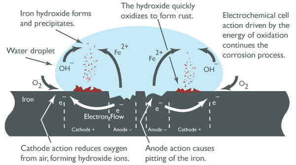
A pipeline’s anti-corrosion coating is designed to protect it from the damaging effects of moisture, salts, and chemicals in the surrounding environment. While the primary pipeline coating protects the entire pipe, the field joint area—the welded section where two pipeline segments meet—is particularly vulnerable. This area is exposed to:
- Welding heat can burn off or degrade the anti-corrosion coating.
- Mechanical stress during installation and transportation can lead to damage.
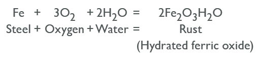
- Environmental factors, such as saltwater or soil moisture, accelerate corrosion at unprotected joints.
Field joint coatings protect these exposed areas, ensuring that the pipeline’s overall anti-corrosion system remains intact. This extends the pipeline’s life and prevents costly repairs or leaks.
2. Common Coating Systems for Pipelines
The choice of an anti-corrosion coating system depends on several factors, including the environment (offshore or onshore), temperature conditions, and the pipeline’s material. The three most common coating systems for oil and gas pipelines are 3LPE, 3LPP، و إف بي إي. Let’s take a closer look at each:
2.1 3LPE (Three-Layer Polyethylene)
- تعبير: Epoxy primer, adhesive layer, and polyethylene outer layer.
- مزايا: Provides excellent corrosion resistance, impact resistance, and mechanical protection. It is widely used for onshore pipelines and offers strong protection in both soil and underwater environments.
2.2 3LPP (Three-Layer Polypropylene)
- تعبير: Epoxy primer, adhesive layer, and polypropylene outer layer.
- مزايا: It offers corrosion protection similar to 3LPE but with better heat resistance. It is ideal for offshore applications where the temperature can fluctuate and higher chemical exposure resistance is needed.
2.3 FBE (Fusion Bonded Epoxy)
- تعبير: A single layer of fusion-bonded epoxy coating.
- مزايا: Excellent adhesion to steel and superior corrosion resistance. FBE coatings are ideal for areas with high exposure to harsh chemicals, making them a go-to choice for critical areas like offshore subsea pipelines.
Each system requires specialized techniques to repair and maintain the coating at the field joint areas, with differences based on the application, environmental conditions, and coating type.
3. Challenges in Pipeline Field Joint Coatings Repair
Repairing the anti-corrosion coating at field joints presents several challenges:
3.1 Heat from Welding
The heat generated during welding can damage the protective coating around the welded area, exposing the metal to corrosion.
3.2 Surface Preparation
To ensure strong adhesion, the surface of the welded joint must be adequately prepared before the coating is applied. This requires careful cleaning to remove weld slag, oxidation, and any residual oil or grease.
3.3 Adhesion Issues
After welding, the exposed metal surface must bond seamlessly with the new coating material. Any irregularities in the surface, such as roughness or contaminants, can lead to poor adhesion and eventual coating failure.
3.4 Environmental Conditions
Offshore and onshore pipelines face differing environmental challenges. Offshore pipelines must withstand saltwater, while onshore pipelines might be subject to soil moisture, UV exposure, and temperature extremes. Each requires a slightly different approach to field joint coating repair.
4. Guide for Pipeline Field Joint Coatings Repair
4.1 Clean and Prepare the Welded Joint Area
Proper surface preparation is the first and most critical step in applying a high-quality field joint coating. This ensures the new coating adheres appropriately and lasts longer.
4.1.1 Remove Weld Slag and Spatter
Mechanical methods like grinders or wire brushes are used to remove all welding slag, spatter, and oxidation around the welded joint. This process ensures that the surface is smooth and free from contaminants. Once two pipes are welded to create a field joint, it must be visually checked for any weld defects, steel defects, or contamination with oil, grease, salts or other loosely adhering materials. Any defects should be reported to the pipeline contractor supervisor and/or repaired according to their procedures and specifications, and if contamination is found, it must be removed before continuing with the next steps.
4.1.2 Clean the Surface
After mechanically cleaning, wipe down the surface with a solvent (such as acetone) to remove any oils, greases, or dirt. This step is critical for ensuring the best possible adhesion of the new coating. Solvents may be used to clean the field joint following the SSPC SP1 Solvent Cleaning standard. Correct cleanliness of the prepared substrate is essential. Usually, a surface cleanliness of ISO 8501-1 Sa 2.5 will be specified along with the required surface profile. Once the required cleanliness and the surface profile have been achieved, a dust contamination check should be carried out according to ISO 8502-3, “Preparation of steel substrates before application of paints and related products – Tests for the assessment of surface cleanliness – part 3: Assessment of dust on steel surfaces prepared for painting (pressure-sensitive tape method)” is the most common method of carrying out this test.
4.1.3 Inspect the Weld Area
Carefully inspect the welded joint and surrounding area for any defects, such as cracks, voids, or porosity. These issues should be addressed before applying the field joint coating.
4.2 Select the Right Field Joint Coating System
The next step is selecting the appropriate coating system. The choice will depend on the pipeline’s leading coating, the operating environment, and the specific characteristics of the weld zone.
4.2.1 طلاءات 3LPE
An epoxy-based repair kit is used to restore the primer and adhesive layers, followed by a polyethylene outer layer. Some systems use Cold-applied PE Tape or Heat-shrinkable PE Sleeves to wrap around the weld area for quick and effective repairs.
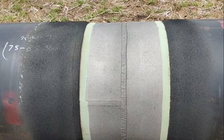
Field Joint Protection Process for 3LPE Anti-corrosion Pipeline
PE Tape
4.2.2 3LPP Coatings
Like 3LPE, Polypropylene-based Wraps or Tapes should be used to ensure they can withstand higher temperatures and typical chemical exposure in offshore environments.
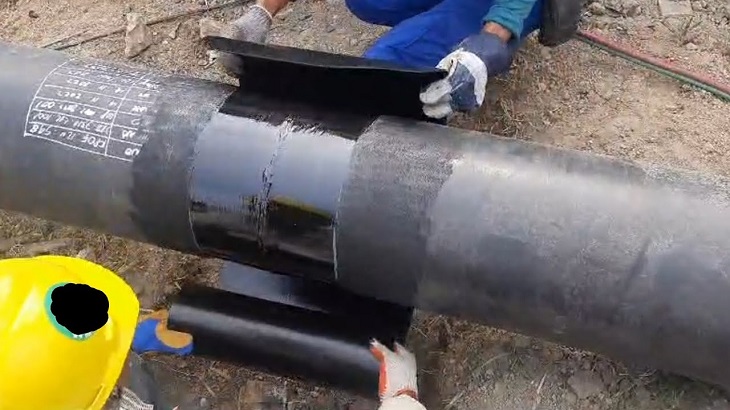
Field Joint Protection Process for 3LPP Anti-corrosion Pipeline
4.2.3 طلاءات FBE
FBE powder أو liquid epoxy is used to repair the field joint. FBE is typically applied by either fluidized bed dipping أو spraying, followed by curing the coating in an oven to achieve the bond.
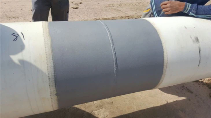
Field Joint Protection Process for FBE Anti-corrosion Pipeline
4.3 Apply the Repair Coating
The field joint coating can be applied once the surface has been prepared and the proper coating system has been selected.
4.3.1 Apply the Primer (if needed)
Depending on the type of coating, an epoxy primer is often applied to the steel surface to ensure a strong bond between the steel and the new coating.
4.3.2 Apply the Bonding Layer
The bonding layer helps to anchor the coating to the steel surface. This layer is significant for 3LPE and 3LPP systems, where a strong adhesive layer ensures the polyethylene or polypropylene sticks securely to the metal.
4.3.3 Apply the Outer Layer
The outer protective layer is the final step in the process. For 3LPE/3LPP, this typically involves wrapping the joint in the protective polyethylene or polypropylene tape. For FBE, this involves applying the epoxy powder or liquid and curing it to create a durable, continuous layer of protection.
4.4 Curing and Inspection
4.4.1 Allow Curing Time
Depending on the repair material used, the coating must be fully cured before the pipeline can be returned to service. This ensures that the coating reaches its full strength and protective properties.
4.4.2 Inspect for Defects
Conduct a thorough inspection once the coating is applied. Look for inconsistencies, gaps, or areas that may not have been covered entirely. If any defects are found, reapply the coating as necessary.
4.4.3 Check Coating Thickness
Measure the thickness of the applied coating to ensure it meets the required specifications. A coating that is too thin may not provide adequate protection.
4.4.4 Conduct a Holiday Test
Use a holiday detector to check for pinholes or voids in the coating. This test involves applying a high-voltage probe to the coated surface and looking for gaps where corrosion could occur.
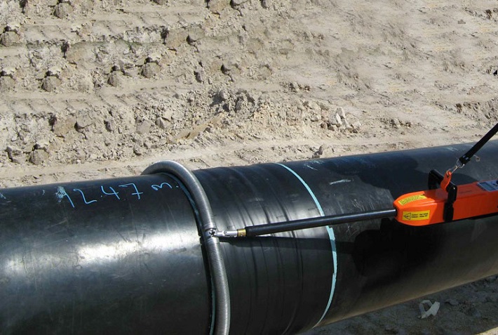
Holiday Test
4.5 Final Quality Control and Documentation
4.5.1 Final Inspection
Once the coating is applied and cured, a final quality control check will be conducted. This includes a visual inspection, measurement of coating thickness, and holiday testing.
4.5.2 Record the Process
Document every step of the repair process, including the materials used, the inspection results, and any testing performed. This documentation is essential for future reference and regulatory compliance.
5. الخاتمة
Pipeline field joint coatings play a critical role in the long-term protection of pipelines, whether they are offshore or onshore. Properly repairing the anti-corrosion coating in the field joint area ensures that the pipeline remains resistant to corrosion, minimizing the risk of leaks, failures, and costly repairs.
By following best practices for cleaning, surface preparation, coating application, and quality control, operators can extend the life of their pipelines, reduce maintenance costs, and ensure compliance with industry standards. Whether you are dealing with 3LPE, 3LPP، أو إف بي إي coated pipelines, investing in high-quality field joint coating repair will provide peace of mind and maximize the operational lifespan of your pipeline.