ZAM Coated Steel for Photovoltaic Brackets

Zinc-Aluminum-Magnesium (ZAM) vs Hot-dip galvanizing (HDG)

정의

What is Zinc-Aluminum-Magnesium (ZAM)?

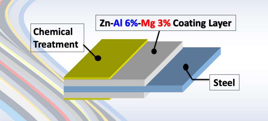
Zinc-aluminum-magnesium (ZAM) is a high-performance metallic coating applied to steel designed to offer superior corrosion resistance, durability, and heat resistance compared to traditional galvanizing (zinc-only coatings). The coating combines zinc (Zn), aluminum (Al), and magnesium (Mg), which provides unique advantages in various applications.
ZAM Coating

ZAM Coating

What is Hot-dip galvanizing? (HDG)?

Hot-dip galvanization is a form of galvanization. It is the process of coating iron and steel with zinc, which alloys with the base metal surface when immersing the metal in a bath of molten zinc at a temperature of around 450 °C (842 °F). When exposed to the atmosphere, the pure zinc (Zn) reacts with oxygen (O2) to form zinc oxide (ZnO), which further reacts with carbon dioxide (CO2) to form zinc carbonate (ZnCO3), a usually dull grey, fairly strong material that protects the steel underneath from further corrosion in many circumstances.

Hot-dip Galvanizing

Hot-dip Galvanizing

Main Differences: Zinc-Aluminum-Magnesium (ZAM) vs Hot-dip galvanizing (HDG)

The comparison between zinc-aluminum-magnesium (ZAM) 그리고 hot-dip galvanizing (HDG) revolves around their coating composition, corrosion resistance, applications, cost, 그리고 environmental impact. Below is a detailed comparison to help understand their differences:

1. Coating Composition

Zinc-Aluminum-Magnesium (ZAM):
ZAM coatings are made of a combination of zinc (Zn), aluminum (Al), 그리고 magnesium (Mg). Typically, the composition is about 80-90% Zinc, 5-11% Aluminum, 그리고 1-3% Magnesium. Including aluminum and magnesium gives the coating superior properties compared to zinc alone.

Hot-Dip Galvanizing (HDG):
HDG involves immersing steel into a molten bath of zinc (Zn) to form a protective zinc coating. The coating consists almost entirely of zinc, with small amounts of iron from the substrate, forming a zinc-iron alloy layer.

2. 내식성

Zinc-Aluminum-Magnesium (ZAM):
Superior corrosion resistance compared to hot-dip galvanized steel. Adding aluminum increases the coating’s resistance to high temperatures and oxidation, while magnesium improves its resistance to corrosion in harsh environments like coastal, industrial, and chemical settings. ZAM has self-healing properties—if the coating is damaged, the magnesium component reacts with moisture to help prevent further corrosion.

Hot-Dip Galvanizing (HDG):
It provides good corrosion resistance but not as high as ZAM, especially in aggressive environments. The zinc coating is sacrificial, meaning it corrodes first to protect the underlying steel, but its effectiveness can be limited in humid, salty, 또는 chemical environments. HDG does not have the advanced self-healing properties that ZAM offers.

3. Durability and Longevity

Zinc-Aluminum-Magnesium (ZAM):
ZAM-coated products can last 2 to 4 times longer than traditional galvanized steel in harsh environments (e.g., coastal areas, chemical plants, etc.). The coating’s enhanced resistance to environmental factors contributes to a longer service life.

Hot-Dip Galvanizing (HDG):
The lifespan of HDG products is good but generally shorter than ZAM, particularly in extreme conditions. HDG can last for many years in less corrosive environments (e.g., mild climates), but its protection may degrade faster in severe environments.

4. Applications

Zinc-Aluminum-Magnesium (ZAM):
Ideal for 혹독한 환경 such as Coastal areas (where saltwater exposure is high), Chemical and industrial environments (where exposure to aggressive substances is every day), Solar panel mounts (due to its superior durability), Heavy-duty industrial applications (e.g., agricultural and mining equipment, steel structures exposed to extreme weather conditions).

Hot-Dip Galvanizing (HDG):
It is commonly used in general construction, automotive industries, outdoor infrastructure, 그리고 agricultural applications. It is suitable for general-purpose corrosion protection in outdoor conditions but not recommended for extreme or coastal environments.

5. Cost

Zinc-Aluminum-Magnesium (ZAM):
It is more expensive than traditional hot-dip galvanizing due to the inclusion of aluminum and magnesium and the more advanced coating process. The longer lifespan and lower maintenance costs in harsh environments often justify the higher initial cost.

Hot-Dip Galvanizing (HDG):
It is cheaper than ZAM, making it more suitable for projects where cost-efficiency is a priority and the environment is less aggressive. The relatively lower cost makes it ideal for large-scale production.

6. Environmental Impact

Zinc-Aluminum-Magnesium (ZAM):
The production of ZAM coatings is more environmentally friendly than hot-dip galvanizing, as it involves lower emissions of harmful gases and waste materials. The production process for ZAM generally generates less waste 그리고 fewer harmful emissions compared to traditional galvanizing methods.

Hot-Dip Galvanizing (HDG):
It is more environmentally intensive than ZAM, producing more waste gases and wastewater. However, modern improvements in the HDG process have aimed to reduce the environmental footprint, though it remains higher than ZAM.

7. Aesthetic Appearance

Zinc-Aluminum-Magnesium (ZAM):
ZAM has a matte gray finish with a smoother, more uniform appearance. This appearance can be more desirable in specific applications like architectural structures or solar panel mounts.

Hot-Dip Galvanizing (HDG):
HDG often has a shiny or dull metallic finish, depending on the thickness of the coating. While durable, its aesthetic appearance may be less appealing than ZAM’s, especially if the finish is uneven.

8. Ease of Processing and Welding

Zinc-Aluminum-Magnesium (ZAM):
ZAM coatings can be more challenging to process, weld, 그리고 paint than traditional galvanized steel, creating issues in some applications.

Hot-Dip Galvanizing (HDG):
HDG products are easier to weld and process than ZAM. However, the zinc coating can make welding and cutting more difficult due to zinc fumes, and special precautions may be required.

Summary Comparison Table: Zinc-Aluminum-Magnesium (ZAM) vs Hot-dip Galvanizing (HDG)

특징 Zinc-Aluminum-Magnesium (ZAM) Hot-Dip Galvanizing (HDG)
Coating Composition Zinc, Aluminum, Magnesium Zinc (with some iron from the substrate)
부식 저항 Superior, especially in harsh environments Good, but less effective in aggressive settings
Durability and Longevity 2-4 times longer than HDG in extreme environments Moderate lifespan, shorter in harsh conditions
응용 Coastal areas, chemical environments, heavy-duty General outdoor infrastructure, agriculture
비용 Higher initial cost Lower initial cost
환경 적 영향 Lower emissions and waste Higher emissions and waste
Aesthetic Appearance Matte gray, smoother finish Shiny or dull metallic finish
Ease of Processing It can be more challenging, especially with welding It is more straightforward to process and weld

결론

ZAM is the best choice for extreme environments where superior corrosion resistance and durability are needed. Its long-term performance can justify the higher upfront cost.

HDG remains the go-to solution for general corrosion protection in less aggressive environments, providing a cost-effective and widely available option for most standard applications.

Pipeline vs Piping

Onshore vs Offshore Pipeline and Piping

소개

In the realm of energy transportation, the distinction between onshore and offshore pipelines and piping systems plays a crucial role in the efficiency, safety, and environmental impact of resource extraction and distribution. Onshore pipelines, typically situated on land, are designed to transport oil, gas, and other fluids over varying distances, benefiting from relatively more straightforward access for maintenance and monitoring. Conversely, offshore pipelines, laid on the seabed or suspended in water, present unique engineering challenges due to harsh marine conditions and logistical complexities. Understanding the Onshore vs Offshore Pipeline and Piping in design, construction, and operational considerations between these two types of pipelines is essential for optimizing infrastructure development and ensuring sustainable practices in the energy sector.

Definition: Onshore vs Offshore Pipeline and Piping

What is Pipeline?

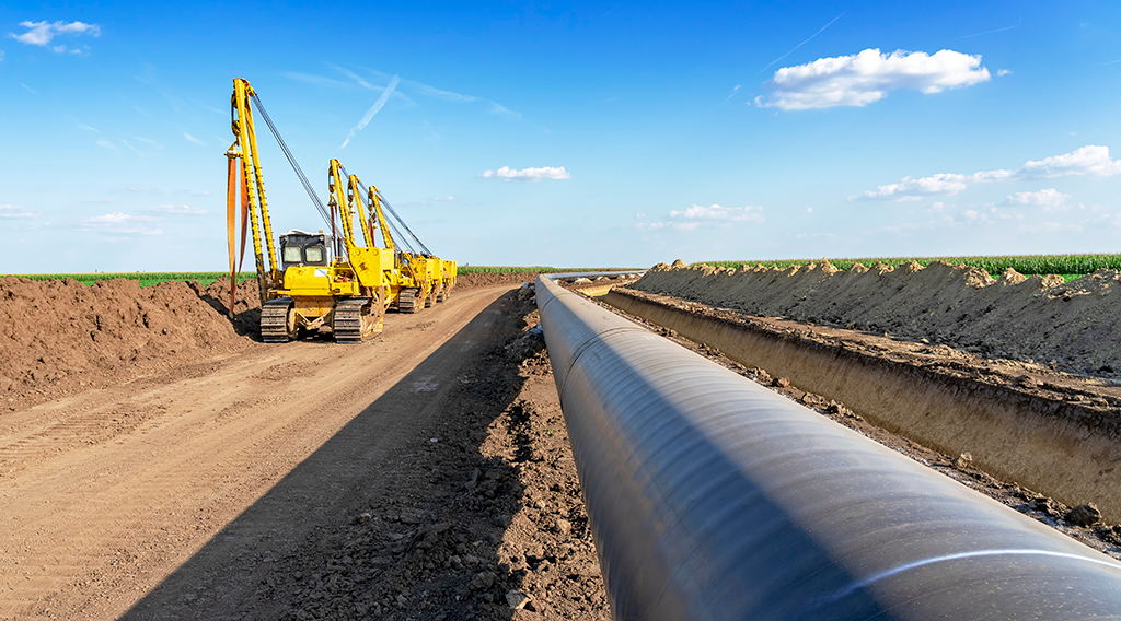
Pipeline is a long series of pipes, usually of large diameter, running underground, aboveground and underwater, such as a submarine pipeline, and equipped with fittings, such as valves and pumps, to control the flow of large quantities of fluid over long distances. Pipelines have large diameters, making it easy to transport liquids or gases in bulk from one place to another, sometimes for thousands of miles.

Pipeline

Pipeline

What is Piping?

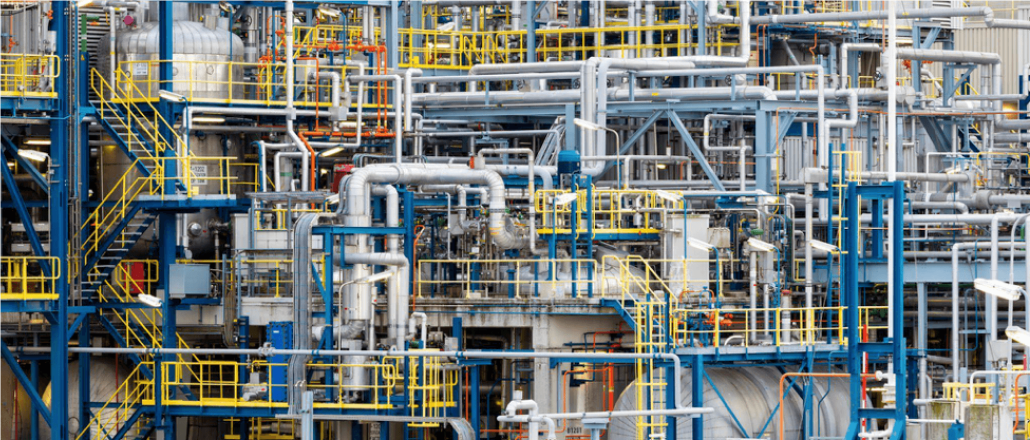
is a system of pipes used to convey fluids (liquids and gases) from one location to another within the designated boundaries or spaces of petrochemical plants, power plants, refineries, etc. It is also equipped with valves and fittings to control the flow of fluids from one facility to another as needed, but only within the plant’s designated boundaries. Never skip these essential topics when taking an online course on piping engineering. Piping diameters range from 1/2 inch to 80 inches, depending on the facility’s design requirements for fluid transportation, usually from one facility to another within the facility’s boundaries.

관

What is Onshore Pipeline?

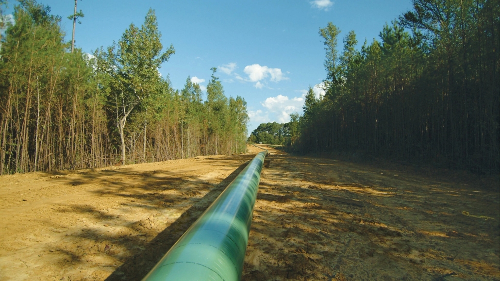
Onshore pipelines refer to networks of pipelines and related equipment used to transport fluids such as oil, natural gas, water, and chemicals in a land environment. These pipelines are integral to long-distance oil and gas transportation from oil fields to refineries, from natural gas wells to gas stations, and from crude oil and refined oil tank farms, chemical tank farms, LNG tank farms, and aircraft refueling pipeline operations.

Onshore Pipeline

Onshore Pipeline

What is Offshore Pipeline?

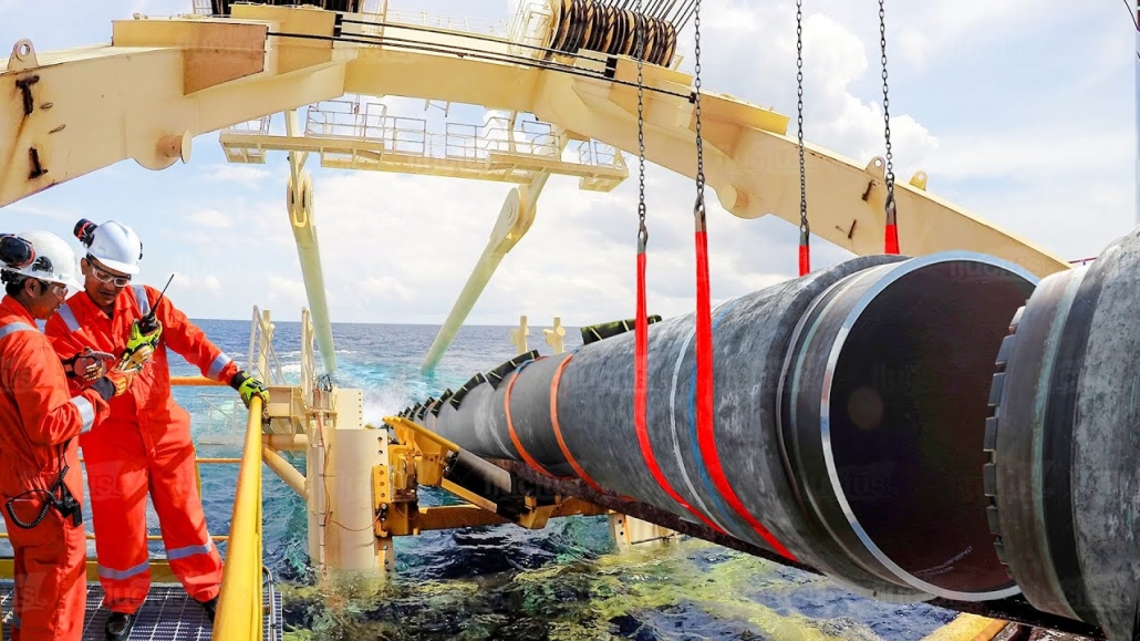
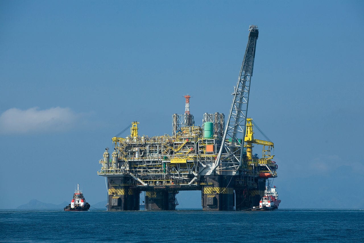
Offshore pipelines refer to the network of pipes and related equipment used to transport fluids such as oil, gas, water, and chemicals in an offshore environment. These pipelines are integral to operating offshore oil rigs, platforms and floating production storage and offloading units (FPSOs). The unique conditions of the offshore environment, such as high salinity, extreme temperatures, and strong currents, present significant challenges to the design and maintenance of these systems.

Offshore Pipeline

Offshore Pipeline

Main Differences: Onshore vs Offshore Pipeline and Piping

Comparison Table: Onshore vs Offshore Pipeline and Piping

사양 육지 난바다 쪽으로 부는
Pipeline Pipeline
디자인 코드 – ASME B31.4: Pipeline Transportation Systems for Liquids and Slurries
– ASME B31.8: Gas Transmission and Distribution Piping Systems
ASME B31.3: Process Piping – DNVGL-ST-F101: Submarine pipeline systems
– API RP 1111: Design, Construction, Operation, and Maintenance of Offshore Hydrocarbon Pipelines (Limit state design)
ASME B31.3: Process Piping
범위 Outside plant boundary
(Villages, fields, rivers, canals, railways, highways, cities, deserts, forests, hills, etc.)
Within plant boundary Outside plant boundary Within plant boundary
Type of pipe API Spec 5L: Specification for Line pipes – ASTM
– BS
– API 5L
API Spec 5L: Specification for Line pipes
– DNVG-ST-F101: Submarine Pipeline Systems
ASTM 표준
밸브 – API 6D: Specification for Pipeline and Piping Valves
– Full Bore (FB) Ball Valves are used for pigs.
– BS
– API Standard
– Full bore (FB) and Reduced bore (RB)
– Full bore Valves: for smooth passage of intelligent pigs
– API 6D SS: Specification on Subsea Pipeline Valves
– RB valves
– BS/API standards
용접 – API Std. 1104: Welding of Pipelines and Related Facilities
– Type of welding: Automatic / Semi-Automatic/ Manual
– ASME Sec. IX: Standard for Welding and Brazing Procedures, Welders, Brazers and Welding and Brazing Operators
– Type of welding: Manual (mostly)
– API Std. 1104: Welding of Pipelines and Related Facilities
– Mostly automatic welding on pipelay barge.
– ASME Sec. IX: Standard for Welding and Brazing Procedures, Welders, Brazers and Welding and Brazing Operators
– Manual welding at the fabrication yard.
Weld joint inspection (NDT requirements) 100% by Automatic UT or RT (by using X-Ray) 5% to 100%
(mostly by using gamma rays)
100% by Automatic UT From 10% to 100% as required
Analyses – Wall Thickness Analysis
– Elastic Bend Radius Analysis
– Stability Analysis for Water Bodies/ Marshy Areas
– Horizontal directional drilling design analysis
– Railroad/ Highway Crossing Analysis
– Casing Pipe Analysis for Crossings
– Seismic Analysis
– Piping wall thickness calculation
– Piping Stress Analysis
Static Analysis
Dynamic Analysis
Wind Analysis
Flange Leakage Analysis
Seismic Analysis
– Wall thickness Analysis
– On-bottom Stability
– Span Analysis
– Global Buckling – Lateral and Upheaval
– Pipeline Expansion Analysis
– Riser Design (Span, Stress & Flexibility Analysis)
– Riser Clamp Design
– Pipeline Crossing Design and Analysis
– Deck piping stress analysis
설치 Buried (mostly) Above ground/On rack/slippers/T-postal etc. Subsea (in water on the seabed or buried in the seabed) Deck Platform Piping
(similar to plant)
Special Installations – Across rivers
– Horizontal Directional Drilling (HDD) method
– Micro-tunnelling method
– Across road/ rail/ highway
– Auger boring/ jacking boring method
– Shallow HDD
– Ghats/ Hills
– Modular installations
– Finning
– Studding
– Jacketing
– Spooling inside warehouse
– U/G piping for cooling water
– S-lay Method (for shallow water installation)
– J-Lay Method (for deep water installation)
– Shore pull/ barge pull near Land Fall Point (LFP)
Along with the deck structure
Special Equipment – Sectionalizing Valves (Remote operated)
– Insulating Joints
– Scraper Launcher/ Receiver
– Stem Extended Valves (for buried valves)
– Flow Tee
– Long Radius bends (R=6D)
– Cold field bends (R = 30D or 40D)
– Expansion Joints
– Motor Operator Valves (MOV)
– Cryogenic Valves
– Springs
– Subsea Isolation Valve (SSIV)
– LR Bends
– Flow tee
– Pipeline End Manifold (PLEM)
– Single Point Mooring (SPM) system
– Submarine hoses
– Floating hoses
– Cables and umbilical installation
– Piggy-back pipelines
해당없음
Survey – Topographical Survey
(all along the pipeline route)
– Geotechnical investigation
(all along the pipeline route)
– Soil resistivity survey
(all along the pipeline route)
– Hydrological Survey for water bodies (for scour depth calculation)
– Cadastral Survey (for RoU acquisition)
– Wind profile from meteorology
– Seismic study of plot
– Geophysical survey/ Bathymetric Survey by using side scan sonar, sub-bottom profiler, and echo-sounder
– Met-Ocean data collection
– Geotechnical data of the pipeline route
해당없음
Corrosion Protection Coating Three Layer Polyethylene (3LPE) coating
Three Layer Polypropylene (3LPP) coating
Fusion bonded epoxy (FBE) coating
– Coal tar enamel (CTE) Coating
Painting Coatings such as:
– Coal Tar Enamel Coating (CTE)
Three-layer polyethylene coating (3LPE)
Three-layer polypropylene coating (3LPP)
– Double-layer fusion bonded epoxy coating (2FBE)
Painting
Cathodic Protection System – Impressed Current Cathodic Protection (ICCP) system
– Sacrificial Anode (limited locations)
Not applicable Sacrificial Anodic Cathodic Protection (SACP) system 해당없음
Hydrostatic testing – Gauge Plate run of 95% of the ID of the highest pipe thickness
– Test Pressure
Minimum: 1.25 times of Design Pressure (for liquid pipelines)
1.25 to 1.5 times of Design Pressure (for gas pipelines)
Maximum: Pressure equivalent to Hoop stress of 95% of SMYS of pipe material
– Hold period: 24 hours
– No gauge plate run is done. Generally, cardboard blasting is done to clean the piping.
– Test Pressure
Minimum: 1.5 × Design Pressure × Temperature Factor
Maximum: Based on line schedule
– Hold period: 2 – 6 hours
– Gauge Plate run of 95% of the ID of the highest pipeline thickness.
– Test Pressure
Minimum: 1.25 times x Design Pressure
– Hold period: 24 hours
– No gauging is done.
– Test Pressure
Maximum: As per line schedule
– Hold period: 2 hours
Preservation – Preservation of pipeline with corrosion-inhibited water or by filling of inert gas (N2) Not applicable
Pigging Intelligent Pigging Not applicable Compliant Not applicable
Machines/Equipment required for installation – Trencher
– Backhoe/ Excavator
– Side Boom
– Cold field bending machine
– Holiday Detection Machines
– Pneumatic/ Hydraulic Internal Clamps
Crane/ Hydra – Pipelay Barge
– Derrick Barge
– Diving support vessel
– Dynamic Positioning (DP) barge (for deepwater)
Pre-fabricated deck piping

Conclusion: Onshore vs Offshore Pipeline and Piping

In summary, Onshore pipelines are usually buried or erected on land to transport oil, natural gas, drinking water, sewage, seawater, slurry, etc. Onshore piping is typically erected in petrochemical plants, power plants, refineries, fire protection systems, water treatment systems, etc., while Offshore pipelines are buried on the seabed. Offshore piping typically consists of transmission and structural support pipeline systems on offshore drilling platforms. Special offshore equipment includes underwater isolation valves, tees, and submarine hoses. Offshore surveys include geophysics, bathymetry, and ocean data collection, while onshore surveys focus on topographic and geotechnical engineering studies.

L80-9Cr vs L80-13Cr

L80-9Cr vs L80-13Cr: Something You Need to Know

Choosing the proper casing and tubing materials can ensure safety and efficiency in oil and gas drilling and exploration. L80-9Cr and L80-13Cr are two alloy steel grades commonly used in petroleum casing and tubing. Each grade has unique characteristics and applications. L80-9Cr vs L80-13Cr, this article will delve into the difference between these materials to help you make an informed decision.

1. Overview of L80 Grade

L80 is an alloy steel used in the oil and gas sector. It is known for its good strength and corrosion resistance. It is typically employed in high-temperature and high-pressure environments and is suitable for both oil and gas production.

1.1 L80-9Cr

Composition: Contains 9% chromium, enhancing the material’s oxidation resistance at high temperatures.
형질:
Corrosion Resistance: It performs well in CO2 environments, making it suitable for acidic gas pipelines.
Mechanical Strength: Provides good strength and is suitable for high-temperature operations.
Applications: Commonly used in high-temperature gas pipelines in oil fields.

1.2 L80-13Cr

Composition: Contains 13% chromium, offering higher corrosion resistance.
형질:
Corrosion Resistance: Exhibits superior performance in environments with H2S and CO2, suitable for extreme conditions.
Mechanical Strength: Offers higher strength and is ideal for complex operational environments.
Applications: Used in high-corrosion environments and deep well operations.

L80-9Cr vs L80-13Cr

L80-9Cr and L80-13Cr Casing and Tubing in Oil and Gas Drilling and Exploration

2. Comparison: L80-9Cr vs L80-13Cr

2.1 Chemical Composition

기준 등급 에스 Cr 구리
API 5CT L80-9크롬 ≤ 0.15 ≤ 1.00 0.30-0.60 ≤ 0.020 ≤ 0.010 8.00-10.00 0.90-1.10 ≤ 0.50 ≤ 0.25
L80-13크롬 0.15-0.22 ≤ 1.00 0.25-1.00 ≤ 0.020 ≤ 0.010 12.00-14.00 ≤ 0.50 ≤ 0.25

2.2 기계적 특성

기준 등급 Yield Strength (Mpa) 인장강도(Mpa) 신율(%) Hardness max
분. max. 분. 분. HRC HBW
API 5CT L80-9크롬 552 655 655 API 5CT
Table C.7
23 241
L80-13크롬 552 655 655 23 241

2.3 Impact Test

기준 등급 Sharpy Impact Energy (J)
Coupling 파이프 본체
API 5CT L80-9크롬 L-10-40-0 T-10-20-0 L-10-27-0 T-10-14-0
L80-13크롬 L-10-40-0 T-10-20-0 L-10-27-0 T-10-14-0

2.4 Corrosion Resistance

L80-9Cr: The 9% chromium content provides moderate corrosion resistance, suitable for environments with low to moderate concentrations of H₂S (hydrogen sulfide) or CO₂ (carbon dioxide), typically seen in less aggressive environments.

L80-13Cr: The 13% chromium content provides enhanced resistance to sour service (i.e., environments with high levels of H₂S) and high CO₂ environments. It’s better for harsher conditions like deep wells or offshore drilling.

2.5 Temperature and Sour Service

L80-9Cr: Generally suitable for moderate-temperature environments.

L80-13Cr: Can withstand higher temperatures and is better equipped for sour service conditions with high concentrations of H₂S or CO₂.

2.6 Cost

L80-9Cr: Due to its lower chromium content, L80-9Cr is less expensive than L80-13Cr. If the environment is not highly corrosive or sour, L80-9Cr could be a more cost-effective option.

L80-13Cr: More expensive but provides superior resistance in harsh conditions, potentially reducing maintenance costs or failures over time.

2.7 Applications

L80-9Cr: Suitable in wells with moderate temperature, pressure, and sour gas conditions. Often used in conventional oil and gas wells or less aggressive service environments.

L80-13Cr: Ideal for high-pressure wells with harsh environmental conditions, particularly in sour gas service, deep wells, or offshore oil & gas operations where high corrosion resistance is critical.

해상 풍력 터빈

육상 및 해상 풍력 터빈을 위한 구조적 원형 중공 섹션

재생 에너지에 대한 수요가 전 세계적으로 계속 증가함에 따라 해상 풍력 발전이 필수적인 솔루션으로 부상했습니다. 이 글에서는 해상 풍력 터빈의 지지 구조에 사용되는 구조적 원형 중공 단면(CHS)의 중요성을 탐구하고, 설계, 재료 특성 및 응용 분야를 살펴봅니다.

1. 구조 원형 중공 단면 이해

구조적 원형 중공 섹션 중공 중앙이 있는 원통형 튜브입니다. 이 섹션은 주로 터빈의 무게를 견디고 외부 환경 압력을 견뎌내도록 설계된 해상 풍력 터빈의 지지 구조에서 중요한 역할을 합니다.

2. 구조용 원형 중공 단면의 재료 특성

탄소강: S355MH, S355MLH, S420MH, S420MLH, S460MH, S460MLH, S460QH, S460QLH, S620QH, S620QLH, S690QH, S690QLH

3. 디자인 고려 사항

해상 풍력 터빈을 위한 지지 구조를 설계할 때 다음과 같은 몇 가지 요소를 고려해야 합니다.
바람 하중: 터빈은 작동 중에 바람에 의해 동적 하중을 받으므로 구조적 안정성을 보장하는 설계가 필요합니다.
파도의 영향: 해양 환경의 파도는 구조물에 추가적인 압력을 가하기 때문에 신중한 계산과 설계 조정이 필요합니다.
부식 방지: 해수의 부식성을 고려할 때, 구조물의 수명을 연장하려면 보호 코팅이나 부식 방지 재료를 사용하는 것이 필수적입니다.

4. 원형 중공 단면 사용의 장점

지지 구조에 원형 중공 섹션을 사용하면 다음과 같은 여러 가지 이점이 있습니다.
높은 압축 강도: 원형 단면은 압력을 균등하게 분산시켜 전반적인 안정성을 향상시킵니다.
경량: 다른 모양과 비교했을 때 원형 튜브는 무게가 줄어 비슷한 강도를 제공하므로 운반과 설치가 용이합니다.
시공의 용이성: 원형 튜브의 연결 및 용접이 간단해 시공 효율성이 높아집니다.

5. 자주 묻는 질문

큐: 구조용 원형 중공 단면에는 어떤 재료를 선택해야 합니까?
에이: 재료 선택은 특정 환경 조건, 예산 및 설계 요구 사항에 따라 달라집니다. 탄소강은 대부분의 응용 분야에 적합하지만 부식성이 높은 환경에서는 스테인리스강 또는 합금강이 더 적합할 수 있습니다.

큐: 구조적 원형 중공 단면의 내구성은 어떻게 보장할 수 있습니까?
에이: 내구성을 보장하려면 정기적인 검사와 유지관리가 필수적입니다. 또한 적절한 보호 코팅과 재료를 선택하면 구조물의 수명을 크게 연장할 수 있습니다.

6. 결론

구조적 원형 중공 섹션은 해상 풍력 터빈의 지지 구조에 없어서는 안 될 요소입니다. 신중한 설계와 재료 선택을 통해 풍력 터빈의 안정성과 내구성을 향상시켜 재생 에너지 개발을 진전시킬 수 있습니다.

육상 및 해상 풍력 터빈 구조용 구조 중공 섹션에 대한 추가 문의나 지원이 필요하면 언제든지 다음 주소로 문의해 주십시오. [email protected].

원유강 생산

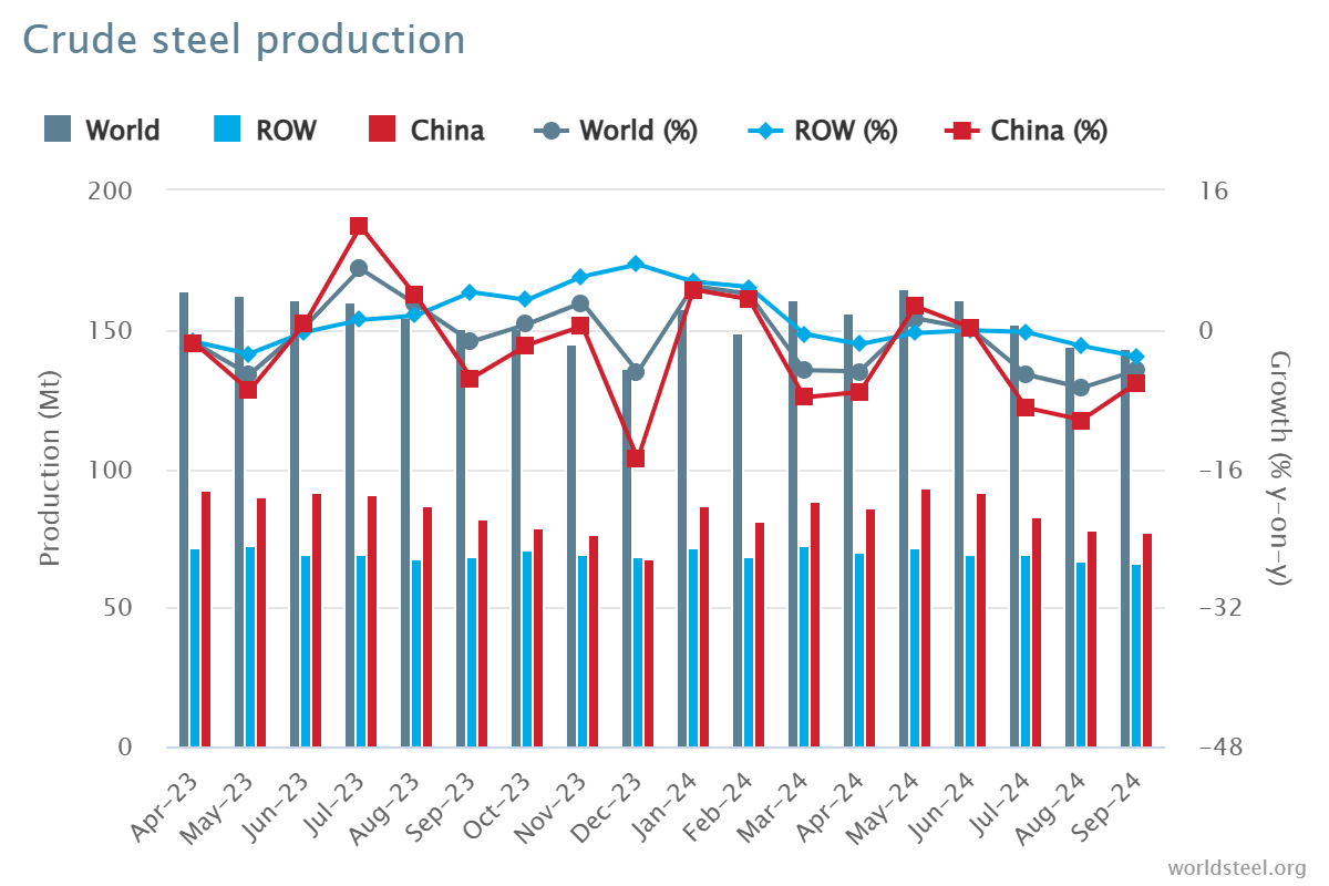
2024년 9월 원유강 생산

2024년 9월, 세계철강협회(World Steel Association)에 보고한 71개국의 전 세계 조강 생산량은 1억 4,360만 톤(Mt)으로 2023년 9월 대비 4.7% 감소했습니다.

조강 생산

조강 생산

지역별 조강 생산량

아프리카는 2024년 9월에 1.9Mt을 생산하여 2023년 9월보다 2.6% 증가했습니다. 아시아와 오세아니아는 105.3Mt을 생산하여 5.0% 감소했습니다. EU(27)는 10.5Mt을 생산하여 0.3% 증가했습니다. 유럽, 기타는 3.6Mt을 생산하여 4.1% 증가했습니다. 중동은 3.5Mt을 생산하여 23.0% 감소했습니다. 북미는 8.6Mt을 생산하여 3.4% 감소했습니다. 러시아 및 기타 CIS + 우크라이나는 6.8Mt을 생산하여 7.6% 감소했습니다. 남미는 3.5Mt을 생산하여 3.3% 증가했습니다.

표 1. 지역별 조강 생산량

지역 2024년 9월(산) % 변경 9월 24/23일 2024년 1월-9월(산) % 1월-9월 24/23 변경
아프리카 1.9 2.6 16.6 2.3
아시아와 오세아니아 105.3 -5 1,032.00 -2.5
유럽연합(27) 10.5 0.3 97.8 1.5
유럽, 기타 3.6 4.1 33.1 7.8
중동 3.5 -23 38.4 -1.5
북아메리카 8.6 -3.4 80 -3.9
러시아 및 기타 CIS + 우크라이나 6.8 -7.6 64.9 -2.5
남아메리카 3.5 3.3 31.4 0
총 71개국 143.6 -4.7 1,394.10 -1.9

이 표에 포함된 71개국은 2023년 전 세계 조강 생산량의 약 98%를 차지했습니다.

표에 포함된 지역 및 국가:

  • 아프리카: 알제리, 이집트, 리비아, 모로코, 남아프리카, 튀니지
  • 아시아 및 오세아니아: 호주, 중국, 인도, 일본, 몽골, 뉴질랜드, 파키스탄, 한국, 대만(중국), 태국, 베트남
  • 유럽연합(27): 오스트리아, 벨기에, 불가리아, 크로아티아, 체코, 핀란드, 프랑스, 독일, 그리스, 헝가리, 이탈리아, 룩셈부르크, 네덜란드, 폴란드, 포르투갈, 루마니아, 슬로바키아, 슬로베니아, 스페인, 스웨덴
  • 유럽, 기타: 마케도니아, 노르웨이, 세르비아, 터키, 영국
  • 중동: 바레인, 이란, 이라크, 요르단, 쿠웨이트, 오만, 카타르, 사우디 아라비아, 아랍에미리트, 예멘
  • 북아메리카: 캐나다, 쿠바, 엘살바도르, 과테말라, 멕시코, 미국
  • 러시아 및 기타 CIS + 우크라이나: 벨로루시, 카자흐스탄, 러시아, 우크라이나
  • 남아메리카: 아르헨티나, 브라질, 칠레, 콜롬비아, 에콰도르, 파라과이, 페루, 우루과이, 베네수엘라

철강 생산국 상위 10개국

중국은 2024년 9월에 77.1Mt을 생산하여 2023년 9월보다 6.1% 감소했습니다. 인도는 11.7Mt을 생산하여 0.2% 감소했습니다. 일본은 6.6Mt을 생산하여 5.8% 감소했습니다. 미국은 6.7Mt을 생산하여 1.2% 증가했습니다. 러시아는 5.6Mt을 생산하여 10.3% 감소한 것으로 추정됩니다. 한국은 5.5Mt을 생산하여 1.3% 증가했습니다. 독일은 3.0Mt을 생산하여 4.3% 증가했습니다. 터키는 3.1Mt을 생산하여 6.5% 증가했습니다. 브라질은 2.8Mt을 생산하여 9.9% 증가했습니다. 이란은 1.5Mt을 생산하여 41.2% 감소한 것으로 추정됩니다.

표 2. 철강 생산국 상위 10개국

지역  2024년 9월(산) % 변경 9월 24/23일 2024년 1월-9월(산) % 1월-9월 24/23 변경
중국 77.1 -6.1 768.5 -3.6
인도 11.7 -0.2 110.3 5.8
일본 6.6 -5.8 63.3 -3.2
미국 6.7 1.2 60.3 -1.6
러시아 5.6 전자 -10.3 54 -5.5
대한민국 5.5 1.3 48.1 -4.6
독일 3 4.3 28.4 4
터키어 3.1 6.5 27.9 13.8
브라질 2.8 9.9 25.2 4.4
이란 1.5 전자 -41.2 21.3 -3.1

e – 추정. 상위 10개 생산국 순위는 연초부터 현재까지의 집계를 기준으로 합니다.

API 5L 대 ISO 3183

차이점 알아보기: API 5L 대 ISO 3183

ISO 3183과 API 5L은 주로 석유, 가스 및 기타 유체 수송 산업에서 사용되는 강관과 관련된 표준입니다. 이 두 표준 사이에는 API 5L 대 ISO 3183 간에 상당한 중복이 있지만 범위, 적용 및 이를 뒷받침하는 조직에서 주요 차이점이 있습니다.

1. 발급 기관: API 5L 대 ISO 3183

API 5L: 미국 석유 협회(API)에서 발행한 이 표준은 주로 석유 및 가스 산업에서 사용됩니다. 석유, 가스 및 물을 운반하는 강관에 대한 기술적 요구 사항을 자세히 설명합니다.
ISO 3183: 국제 표준화 기구(ISO)에서 발행한 이 표준은 국제적으로 인정받으며 석유 및 가스 수송 분야의 강관에 대해 전 세계적으로 사용되고 있습니다.

2. 적용 범위: API 5L 대 ISO 3183

API 5L: 석유, 천연가스 및 기타 유체를 고압으로 운반하는 강관을 포함합니다. 북미, 특히 미국에서 널리 사용됩니다.
ISO 3183: 이 표준은 주로 석유 및 가스 파이프라인에 사용되는 강관의 설계, 제조 및 품질 관리에 중점을 두고 있지만, 전 세계 여러 국가에서 국제적으로 사용되고 적용 범위가 더 넓습니다.

3. 주요 차이점: API 5L 대 ISO 3183

지리적 및 시장 초점:

API 5L은 북미 시장(특히 미국)에 더 맞춰져 있는 반면, ISO 3183은 국제적으로 적용 가능하며 전 세계 많은 국가에서 사용되고 있습니다.

강철 등급 및 요구 사항:

API 5L은 L175, L210, L245 등의 강철 등급을 정의하며, 여기서 숫자는 최소 항복 강도를 메가파스칼(MPa) 단위로 나타냅니다.
ISO 3183도 비슷한 등급을 정의하지만, 국제 산업 관행에 맞춰 재료 특성, 제조 공정 및 검사 프로토콜에 대한 요구 사항이 더 자세합니다.
추가 사양:
API 5L은 품질 관리, 인증 및 생산 요구 사항을 강조하는 반면, ISO 3183은 국제 무역을 염두에 두고 더 광범위한 범위를 포괄하며 온도, 환경 및 특정 기계적 요구 사항을 포함한 다양한 조건에 대한 사양을 제공합니다.

4. 기술 요구 사항: API 5L 대 ISO 3183

API 5L은 강관의 재료 특성, 제조 공정, 치수, 시험 방법 및 품질 관리를 명시합니다. L(저강도)에서 X 등급(고강도)까지 강철 등급을 정의합니다(예: X42, X60 및 X70).
ISO 3183은 재료 품질, 열처리, 표면 처리 및 파이프 끝을 포함하여 강관 제조의 유사한 측면을 다룹니다. 또한 파이프라인 설계 압력, 환경 고려 사항 및 다양한 파이프라인 액세서리에 대한 자세한 사양을 제공합니다.

5. 파이프 등급 비교: API 5L 대 ISO 3183

API 5L: 등급은 L 등급(낮은 항복 강도)에서 X 등급(높은 항복 강도)까지 다양합니다. 예를 들어, X60은 항복 강도가 60,000psi(약 413MPa)인 파이프를 나타냅니다.
ISO 3183: 유사한 등급 시스템을 사용하지만 더 자세한 분류 및 조건을 포함할 수 있습니다. 또한 글로벌 파이프라인 설계 및 운영 관행과의 일치를 보장합니다.

6. 표준 간의 호환성:

많은 경우 API 5L과 ISO 3183은 호환되므로 API 5L의 요구 사항을 충족하는 강관은 일반적으로 ISO 3183의 요구 사항도 충족하며 그 반대의 경우도 마찬가지입니다. 그러나 특정 파이프라인 프로젝트는 위치, 고객 선호도 또는 규제 요구 사항에 따라 한 표준을 다른 표준보다 준수할 수 있습니다.

7. 결론:

API 5L은 미국과 주변 지역에서 더 일반적입니다. 석유 및 가스 파이프라인 산업에 초점을 맞추고 생산 및 품질 관리를 강조합니다.
ISO 3183은 글로벌 석유 및 가스 파이프라인 프로젝트를 위한 국제 표준입니다. 보다 자세하고 전 세계적으로 일치하는 요구 사항은 국제 시장에서 더 광범위한 수용을 보장합니다.

두 표준은 재료, 제조 및 테스트 사양과 관련하여 매우 유사합니다. 그래도 ISO 3183은 더 광범위하고 전 세계적으로 적용 가능한 범위를 갖는 경향이 있는 반면 API 5L은 북미 시장에 더 구체적으로 남아 있습니다. 이러한 표준 간의 선택은 파이프라인 프로젝트의 지리적 위치, 사양 및 규제 요구 사항에 따라 달라집니다.