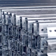
ZAM Coated Steel for Photovoltaic Brackets

Zinc-Aluminum-Magnesium (ZAM) vs Hot-dip galvanizing (HDG)

Definisi

What is Zinc-Aluminum-Magnesium (ZAM)?

Zinc-aluminum-magnesium (ZAM) is a high-performance metallic coating applied to steel designed to offer superior corrosion resistance, durability, and heat resistance compared to traditional galvanizing (zinc-only coatings). The coating combines zinc (Zn), aluminum (Al), and magnesium (Mg), which provides unique advantages in various applications.
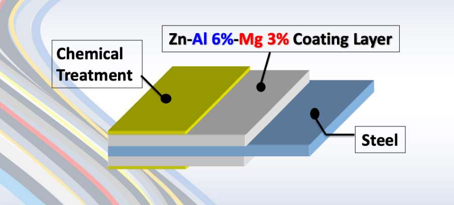
ZAM Coating

ZAM Coating

What is Hot-dip galvanizing? (HDG)?

Hot-dip galvanization is a form of galvanization. It is the process of coating iron and steel with zinc, which alloys with the base metal surface when immersing the metal in a bath of molten zinc at a temperature of around 450 °C (842 °F). When exposed to the atmosphere, the pure zinc (Zn) reacts with oxygen (O2) to form zinc oxide (ZnO), which further reacts with carbon dioxide (CO2) to form zinc carbonate (ZnCO3), a usually dull grey, fairly strong material that protects the steel underneath from further corrosion in many circumstances.

Hot-dip Galvanizing

Hot-dip Galvanizing

Main Differences: Zinc-Aluminum-Magnesium (ZAM) vs Hot-dip galvanizing (HDG)

The comparison between zinc-aluminum-magnesium (ZAM) Dan hot-dip galvanizing (HDG) revolves around their coating composition, corrosion resistance, applications, cost, Dan environmental impact. Below is a detailed comparison to help understand their differences:

1. Coating Composition

Zinc-Aluminum-Magnesium (ZAM):
ZAM coatings are made of a combination of zinc (Zn), aluminum (Al), Dan magnesium (Mg). Typically, the composition is about 80-90% Zinc, 5-11% Aluminum, Dan 1-3% Magnesium. Including aluminum and magnesium gives the coating superior properties compared to zinc alone.

Hot-Dip Galvanizing (HDG):
HDG involves immersing steel into a molten bath of zinc (Zn) to form a protective zinc coating. The coating consists almost entirely of zinc, with small amounts of iron from the substrate, forming a zinc-iron alloy layer.

2. Ketahanan Korosi

Zinc-Aluminum-Magnesium (ZAM):
Superior corrosion resistance compared to hot-dip galvanized steel. Adding aluminum increases the coating’s resistance to high temperatures and oxidation, while magnesium improves its resistance to corrosion in harsh environments like coastal, industrial, and chemical settings. ZAM has self-healing properties—if the coating is damaged, the magnesium component reacts with moisture to help prevent further corrosion.

Hot-Dip Galvanizing (HDG):
It provides good corrosion resistance but not as high as ZAM, especially in aggressive environments. The zinc coating is sacrificial, meaning it corrodes first to protect the underlying steel, but its effectiveness can be limited in humid, salty, atau chemical environments. HDG does not have the advanced self-healing properties that ZAM offers.

3. Durability and Longevity

Zinc-Aluminum-Magnesium (ZAM):
ZAM-coated products can last 2 to 4 times longer than traditional galvanized steel in harsh environments (e.g., coastal areas, chemical plants, etc.). The coating’s enhanced resistance to environmental factors contributes to a longer service life.

Hot-Dip Galvanizing (HDG):
The lifespan of HDG products is good but generally shorter than ZAM, particularly in extreme conditions. HDG can last for many years in less corrosive environments (e.g., mild climates), but its protection may degrade faster in severe environments.

4. Applications

Zinc-Aluminum-Magnesium (ZAM):
Ideal for lingkungan yang keras such as Coastal areas (where saltwater exposure is high), Chemical and industrial environments (where exposure to aggressive substances is every day), Solar panel mounts (due to its superior durability), Heavy-duty industrial applications (e.g., agricultural and mining equipment, steel structures exposed to extreme weather conditions).

Hot-Dip Galvanizing (HDG):
It is commonly used in general construction, automotive industries, outdoor infrastructure, Dan agricultural applications. It is suitable for general-purpose corrosion protection in outdoor conditions but not recommended for extreme or coastal environments.

5. Cost

Zinc-Aluminum-Magnesium (ZAM):
It is more expensive than traditional hot-dip galvanizing due to the inclusion of aluminum and magnesium and the more advanced coating process. The longer lifespan and lower maintenance costs in harsh environments often justify the higher initial cost.

Hot-Dip Galvanizing (HDG):
It is cheaper than ZAM, making it more suitable for projects where cost-efficiency is a priority and the environment is less aggressive. The relatively lower cost makes it ideal for large-scale production.

6. Environmental Impact

Zinc-Aluminum-Magnesium (ZAM):
The production of ZAM coatings is more environmentally friendly than hot-dip galvanizing, as it involves lower emissions of harmful gases and waste materials. The production process for ZAM generally generates less waste Dan fewer harmful emissions compared to traditional galvanizing methods.

Hot-Dip Galvanizing (HDG):
It is more environmentally intensive than ZAM, producing more waste gases and wastewater. However, modern improvements in the HDG process have aimed to reduce the environmental footprint, though it remains higher than ZAM.

7. Aesthetic Appearance

Zinc-Aluminum-Magnesium (ZAM):
ZAM has a matte gray finish with a smoother, more uniform appearance. This appearance can be more desirable in specific applications like architectural structures or solar panel mounts.

Hot-Dip Galvanizing (HDG):
HDG often has a shiny or dull metallic finish, depending on the thickness of the coating. While durable, its aesthetic appearance may be less appealing than ZAM’s, especially if the finish is uneven.

8. Ease of Processing and Welding

Zinc-Aluminum-Magnesium (ZAM):
ZAM coatings can be more challenging to process, weld, Dan paint than traditional galvanized steel, creating issues in some applications.

Hot-Dip Galvanizing (HDG):
HDG products are easier to weld and process than ZAM. However, the zinc coating can make welding and cutting more difficult due to zinc fumes, and special precautions may be required.

Summary Comparison Table: Zinc-Aluminum-Magnesium (ZAM) vs Hot-dip Galvanizing (HDG)

Fitur Zinc-Aluminum-Magnesium (ZAM) Hot-Dip Galvanizing (HDG)
Coating Composition Zinc, Aluminum, Magnesium Zinc (with some iron from the substrate)
Tahan korosi Superior, especially in harsh environments Good, but less effective in aggressive settings
Durability and Longevity 2-4 times longer than HDG in extreme environments Moderate lifespan, shorter in harsh conditions
Aplikasi Coastal areas, chemical environments, heavy-duty General outdoor infrastructure, agriculture
Biaya Higher initial cost Lower initial cost
Dampak lingkungan Lower emissions and waste Higher emissions and waste
Aesthetic Appearance Matte gray, smoother finish Shiny or dull metallic finish
Ease of Processing It can be more challenging, especially with welding It is more straightforward to process and weld

Kesimpulan

ZAM is the best choice for extreme environments where superior corrosion resistance and durability are needed. Its long-term performance can justify the higher upfront cost.

HDG remains the go-to solution for general corrosion protection in less aggressive environments, providing a cost-effective and widely available option for most standard applications.

Pipeline vs Piping

Onshore vs Offshore Pipeline and Piping

Perkenalan

In the realm of energy transportation, the distinction between onshore and offshore pipelines and piping systems plays a crucial role in the efficiency, safety, and environmental impact of resource extraction and distribution. Onshore pipelines, typically situated on land, are designed to transport oil, gas, and other fluids over varying distances, benefiting from relatively more straightforward access for maintenance and monitoring. Conversely, offshore pipelines, laid on the seabed or suspended in water, present unique engineering challenges due to harsh marine conditions and logistical complexities. Understanding the Onshore vs Offshore Pipeline and Piping in design, construction, and operational considerations between these two types of pipelines is essential for optimizing infrastructure development and ensuring sustainable practices in the energy sector.

Definition: Onshore vs Offshore Pipeline and Piping

What is Pipeline?

Pipeline is a long series of pipes, usually of large diameter, running underground, aboveground and underwater, such as a submarine pipeline, and equipped with fittings, such as valves and pumps, to control the flow of large quantities of fluid over long distances. Pipelines have large diameters, making it easy to transport liquids or gases in bulk from one place to another, sometimes for thousands of miles.

Pipeline

Pipeline

What is Piping?

Perpipaan is a system of pipes used to convey fluids (liquids and gases) from one location to another within the designated boundaries or spaces of petrochemical plants, power plants, refineries, etc. It is also equipped with valves and fittings to control the flow of fluids from one facility to another as needed, but only within the plant’s designated boundaries. Never skip these essential topics when taking an online course on piping engineering. Piping diameters range from 1/2 inch to 80 inches, depending on the facility’s design requirements for fluid transportation, usually from one facility to another within the facility’s boundaries.

Perpipaan

Perpipaan

What is Onshore Pipeline?

Onshore pipelines refer to networks of pipelines and related equipment used to transport fluids such as oil, natural gas, water, and chemicals in a land environment. These pipelines are integral to long-distance oil and gas transportation from oil fields to refineries, from natural gas wells to gas stations, and from crude oil and refined oil tank farms, chemical tank farms, LNG tank farms, and aircraft refueling pipeline operations.

Onshore Pipeline

Onshore Pipeline

What is Offshore Pipeline?

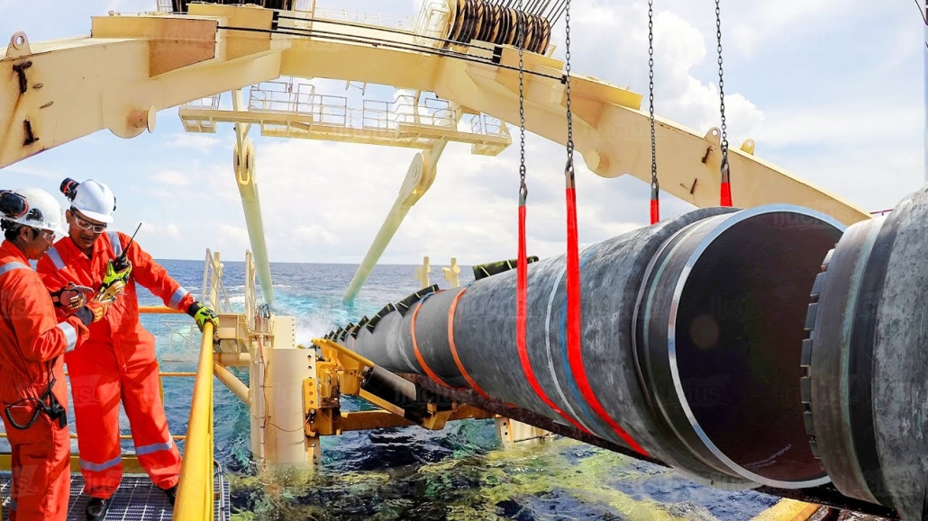
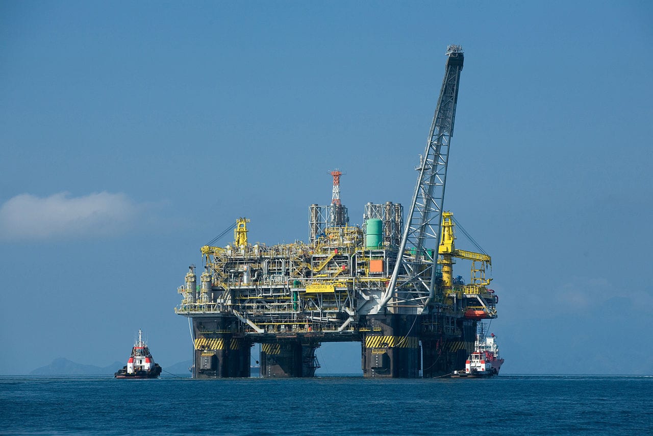
Offshore pipelines refer to the network of pipes and related equipment used to transport fluids such as oil, gas, water, and chemicals in an offshore environment. These pipelines are integral to operating offshore oil rigs, platforms and floating production storage and offloading units (FPSOs). The unique conditions of the offshore environment, such as high salinity, extreme temperatures, and strong currents, present significant challenges to the design and maintenance of these systems.

Offshore Pipeline

Offshore Pipeline

Main Differences: Onshore vs Offshore Pipeline and Piping

Comparison Table: Onshore vs Offshore Pipeline and Piping

Spesifikasi Daratan Di lepas pantai
Pipeline Perpipaan Pipeline Perpipaan
Kode Desain – ASME B31.4: Pipeline Transportation Systems for Liquids and Slurries
– ASME B31.8: Gas Transmission and Distribution Piping Systems
ASME B31.3: Process Piping – DNVGL-ST-F101: Submarine pipeline systems
– API RP 1111: Design, Construction, Operation, and Maintenance of Offshore Hydrocarbon Pipelines (Limit state design)
ASME B31.3: Process Piping
Cakupan Outside plant boundary
(Villages, fields, rivers, canals, railways, highways, cities, deserts, forests, hills, etc.)
Within plant boundary Outside plant boundary Within plant boundary
Type of pipe API Spec 5L: Specification for Line pipes – ASTM
– BS
– API 5L
API Spec 5L: Specification for Line pipes
– DNVGL-ST-F101: Submarine Pipeline Systems
Standar ASTM
Katup – API 6D: Specification for Pipeline and Piping Valves
– Full Bore (FB) Ball Valves are used for pigs.
– BS
– API Standard
– Full bore (FB) and Reduced bore (RB)
– Full bore Valves: for smooth passage of intelligent pigs
– API 6D SS: Specification on Subsea Pipeline Valves
– RB valves
– BS/API standards
Pengelasan – API Std. 1104: Welding of Pipelines and Related Facilities
– Type of welding: Automatic / Semi-Automatic/ Manual
– ASME Sec. IX: Standard for Welding and Brazing Procedures, Welders, Brazers and Welding and Brazing Operators
– Type of welding: Manual (mostly)
– API Std. 1104: Welding of Pipelines and Related Facilities
– Mostly automatic welding on pipelay barge.
– ASME Sec. IX: Standard for Welding and Brazing Procedures, Welders, Brazers and Welding and Brazing Operators
– Manual welding at the fabrication yard.
Weld joint inspection (NDT requirements) 100% by Automatic UT or RT (by using X-Ray) 5% to 100%
(mostly by using gamma rays)
100% by Automatic UT From 10% to 100% as required
Analyses – Wall Thickness Analysis
– Elastic Bend Radius Analysis
– Stability Analysis for Water Bodies/ Marshy Areas
– Horizontal directional drilling design analysis
– Railroad/ Highway Crossing Analysis
– Casing Pipe Analysis for Crossings
– Seismic Analysis
– Piping wall thickness calculation
– Piping Stress Analysis
Static Analysis
Dynamic Analysis
Wind Analysis
Flange Leakage Analysis
Seismic Analysis
– Wall thickness Analysis
– On-bottom Stability
– Span Analysis
– Global Buckling – Lateral and Upheaval
– Pipeline Expansion Analysis
– Riser Design (Span, Stress & Flexibility Analysis)
– Riser Clamp Design
– Pipeline Crossing Design and Analysis
– Deck piping stress analysis
Instalasi Buried (mostly) Above ground/On rack/slippers/T-postal etc. Subsea (in water on the seabed or buried in the seabed) Deck Platform Piping
(similar to plant)
Special Installations – Across rivers
– Horizontal Directional Drilling (HDD) method
– Micro-tunnelling method
– Across road/ rail/ highway
– Auger boring/ jacking boring method
– Shallow HDD
– Ghats/ Hills
– Modular installations
– Finning
– Studding
– Jacketing
– Spooling inside warehouse
– U/G piping for cooling water
– S-lay Method (for shallow water installation)
– J-Lay Method (for deep water installation)
– Shore pull/ barge pull near Land Fall Point (LFP)
Along with the deck structure
Special Equipment – Sectionalizing Valves (Remote operated)
– Insulating Joints
– Scraper Launcher/ Receiver
– Stem Extended Valves (for buried valves)
– Flow Tee
– Long Radius bends (R=6D)
– Cold field bends (R = 30D or 40D)
– Expansion Joints
– Motor Operator Valves (MOV)
– Cryogenic Valves
– Springs
– Subsea Isolation Valve (SSIV)
– LR Bends
– Flow tee
– Pipeline End Manifold (PLEM)
– Single Point Mooring (SPM) system
– Submarine hoses
– Floating hoses
– Cables and umbilical installation
– Piggy-back pipelines
Tidak Berlaku
Survey – Topographical Survey
(all along the pipeline route)
– Geotechnical investigation
(all along the pipeline route)
– Soil resistivity survey
(all along the pipeline route)
– Hydrological Survey for water bodies (for scour depth calculation)
– Cadastral Survey (for RoU acquisition)
– Wind profile from meteorology
– Seismic study of plot
– Geophysical survey/ Bathymetric Survey by using side scan sonar, sub-bottom profiler, and echo-sounder
– Met-Ocean data collection
– Geotechnical data of the pipeline route
Tidak Berlaku
Corrosion Protection Coating Three Layer Polyethylene (3LPE) coating
Three Layer Polypropylene (3LPP) coating
Fusion bonded epoxy (FBE) coating
– Coal tar enamel (CTE) Coating
Painting Coatings such as:
– Coal Tar Enamel Coating (CTE)
Three-layer polyethylene coating (3LPE)
Three-layer polypropylene coating (3LPP)
– Double-layer fusion bonded epoxy coating (2FBE)
Painting
Cathodic Protection System – Impressed Current Cathodic Protection (ICCP) system
– Sacrificial Anode (limited locations)
Not applicable Sacrificial Anodic Cathodic Protection (SACP) system Tidak Berlaku
Hydrostatic testing – Gauge Plate run of 95% of the ID of the highest pipe thickness
– Test Pressure
Minimum: 1.25 times of Design Pressure (for liquid pipelines)
1.25 to 1.5 times of Design Pressure (for gas pipelines)
Maximum: Pressure equivalent to Hoop stress of 95% of SMYS of pipe material
– Hold period: 24 hours
– No gauge plate run is done. Generally, cardboard blasting is done to clean the piping.
– Test Pressure
Minimum: 1.5 × Design Pressure × Temperature Factor
Maximum: Based on line schedule
– Hold period: 2 – 6 hours
– Gauge Plate run of 95% of the ID of the highest pipeline thickness.
– Test Pressure
Minimum: 1.25 times x Design Pressure
– Hold period: 24 hours
– No gauging is done.
– Test Pressure
Maximum: As per line schedule
– Hold period: 2 hours
Preservation – Preservation of pipeline with corrosion-inhibited water or by filling of inert gas (N2) Not applicable
Pigging Intelligent Pigging Not applicable Compliant Not applicable
Machines/Equipment required for installation – Trencher
– Backhoe/ Excavator
– Side Boom
– Cold field bending machine
– Holiday Detection Machines
– Pneumatic/ Hydraulic Internal Clamps
Crane/ Hydra – Pipelay Barge
– Derrick Barge
– Diving support vessel
– Dynamic Positioning (DP) barge (for deepwater)
Pre-fabricated deck piping

Conclusion: Onshore vs Offshore Pipeline and Piping

In summary, Onshore pipelines are usually buried or erected on land to transport oil, natural gas, drinking water, sewage, seawater, slurry, etc. Onshore piping is typically erected in petrochemical plants, power plants, refineries, fire protection systems, water treatment systems, etc., while Offshore pipelines are buried on the seabed. Offshore piping typically consists of transmission and structural support pipeline systems on offshore drilling platforms. Special offshore equipment includes underwater isolation valves, tees, and submarine hoses. Offshore surveys include geophysics, bathymetry, and ocean data collection, while onshore surveys focus on topographic and geotechnical engineering studies.

L80-9Cr vs L80-13Cr

L80-9Cr vs L80-13Cr: Something You Need to Know

Choosing the proper casing and tubing materials can ensure safety and efficiency in oil and gas drilling and exploration. L80-9Cr and L80-13Cr are two alloy steel grades commonly used in petroleum casing and tubing. Each grade has unique characteristics and applications. L80-9Cr vs L80-13Cr, this article will delve into the difference between these materials to help you make an informed decision.

1. Overview of L80 Grade

L80 is an alloy steel used in the oil and gas sector. It is known for its good strength and corrosion resistance. It is typically employed in high-temperature and high-pressure environments and is suitable for both oil and gas production.

1.1 L80-9Cr

Composition: Contains 9% chromium, enhancing the material’s oxidation resistance at high temperatures.
Karakteristik:
Corrosion Resistance: It performs well in CO2 environments, making it suitable for acidic gas pipelines.
Mechanical Strength: Provides good strength and is suitable for high-temperature operations.
Applications: Commonly used in high-temperature gas pipelines in oil fields.

1.2 L80-13Cr

Composition: Contains 13% chromium, offering higher corrosion resistance.
Karakteristik:
Corrosion Resistance: Exhibits superior performance in environments with H2S and CO2, suitable for extreme conditions.
Mechanical Strength: Offers higher strength and is ideal for complex operational environments.
Applications: Used in high-corrosion environments and deep well operations.

L80-9Cr vs L80-13Cr

L80-9Cr and L80-13Cr Casing and Tubing in Oil and Gas Drilling and Exploration

2. Comparison: L80-9Cr vs L80-13Cr

2.1 Chemical Composition

Standar Nilai C Ya M N P S Kr Mo Tidak Cu
API 5CT L80-9Cr ≤ 0,15 ≤ 1.00 0.30-0.60 ≤ 0,020 ≤ 0,010 8.00-10.00 0.90-1.10 ≤ 0.50 ≤ 0,25
L80-13Cr 0.15-0.22 ≤ 1.00 0.25-1.00 ≤ 0,020 ≤ 0,010 12.00-14.00 ≤ 0.50 ≤ 0,25

2.2 Sifat Mekanik

Standar Nilai Yield Strength (Mpa) Kekuatan Tarik (Mpa) Perpanjangan (%) Hardness max
menit. max. menit. menit. HRC PBR
API 5CT L80-9Cr 552 655 655 API 5CT
Table C.7
23 241
L80-13Cr 552 655 655 23 241

2.3 Impact Test

Standar Nilai Sharpy Impact Energy (J)
Coupling Badan Pipa
API 5CT L80-9Cr L-10-40-0 T-10-20-0 L-10-27-0 T-10-14-0
L80-13Cr L-10-40-0 T-10-20-0 L-10-27-0 T-10-14-0

2.4 Corrosion Resistance

L80-9Cr: The 9% chromium content provides moderate corrosion resistance, suitable for environments with low to moderate concentrations of H₂S (hydrogen sulfide) or CO₂ (carbon dioxide), typically seen in less aggressive environments.

L80-13Cr: The 13% chromium content provides enhanced resistance to sour service (i.e., environments with high levels of H₂S) and high CO₂ environments. It’s better for harsher conditions like deep wells or offshore drilling.

2.5 Temperature and Sour Service

L80-9Cr: Generally suitable for moderate-temperature environments.

L80-13Cr: Can withstand higher temperatures and is better equipped for sour service conditions with high concentrations of H₂S or CO₂.

2.6 Cost

L80-9Cr: Due to its lower chromium content, L80-9Cr is less expensive than L80-13Cr. If the environment is not highly corrosive or sour, L80-9Cr could be a more cost-effective option.

L80-13Cr: More expensive but provides superior resistance in harsh conditions, potentially reducing maintenance costs or failures over time.

2.7 Applications

L80-9Cr: Suitable in wells with moderate temperature, pressure, and sour gas conditions. Often used in conventional oil and gas wells or less aggressive service environments.

L80-13Cr: Ideal for high-pressure wells with harsh environmental conditions, particularly in sour gas service, deep wells, or offshore oil & gas operations where high corrosion resistance is critical.

Turbin Angin Lepas Pantai

Penampang Berongga Lingkaran Struktural untuk Turbin Angin Darat dan Lepas Pantai

Karena permintaan energi terbarukan terus meningkat secara global, tenaga angin lepas pantai telah muncul sebagai solusi penting. Artikel ini membahas secara mendalam tentang pentingnya penampang melingkar berongga (CHS) struktural yang digunakan dalam struktur pendukung turbin angin lepas pantai, mengeksplorasi desain, sifat material, dan aplikasinya.

1. Memahami Penampang Berongga Lingkaran Struktural

Bagian berongga melingkar struktural adalah tabung silinder dengan bagian tengah berongga. Bagian-bagian ini memainkan peran penting dalam struktur pendukung turbin angin lepas pantai, yang terutama dirancang untuk menahan berat turbin dan menahan tekanan lingkungan eksternal.

2. Sifat Material Penampang Berongga Lingkaran Struktural

Baja Karbon: S355MH, S355MLH, S420MH, S420MLH, S460MH, S460MLH, S460QH, S460QLH, S620QH, S620QLH, S690QH, S690QLH

3. Pertimbangan Desain

Saat merancang struktur pendukung untuk turbin angin lepas pantai, beberapa faktor harus dipertimbangkan:
Beban Angin: Turbin mengalami beban dinamis dari angin selama operasi, memerlukan desain yang memastikan stabilitas struktural.
Dampak Gelombang: Gelombang di lingkungan laut memberikan tekanan tambahan pada struktur, sehingga memerlukan perhitungan cermat dan penyesuaian desain.
Perlindungan Korosi: Mengingat sifat korosif air laut, penggunaan lapisan pelindung atau bahan anti korosi sangat penting untuk memperpanjang umur struktur.

4. Keuntungan Menggunakan Bagian Berongga Melingkar

Penggunaan bagian berongga melingkar pada struktur pendukung menawarkan beberapa manfaat:
Kekuatan Kompresi Tinggi: Penampang melingkar memungkinkan distribusi tekanan yang merata, meningkatkan stabilitas keseluruhan.
Ringan: Dibandingkan dengan bentuk lain, tabung melingkar memberikan kekuatan yang sama dengan bobot yang lebih ringan, sehingga memudahkan transportasi dan pemasangan.
Kemudahan Konstruksi: Kesederhanaan dalam menyambungkan dan mengelas tabung melingkar meningkatkan efisiensi konstruksi.

5. Pertanyaan yang Sering Diajukan

Q: Material apakah yang sebaiknya dipilih untuk bagian berongga melingkar struktural?
A: Pemilihan material bergantung pada kondisi lingkungan tertentu, anggaran, dan persyaratan desain. Baja karbon cocok untuk sebagian besar aplikasi, tetapi di lingkungan yang sangat korosif, baja tahan karat atau baja paduan mungkin lebih sesuai.

Q: Bagaimana ketahanan bagian berongga melingkar struktural dapat dipastikan?
A: Pemeriksaan dan perawatan rutin sangat penting untuk memastikan ketahanan. Selain itu, pemilihan lapisan pelindung dan material yang tepat dapat memperpanjang umur struktur secara signifikan.

6. Kesimpulan

Bagian berongga melingkar struktural sangat diperlukan dalam struktur pendukung turbin angin lepas pantai. Melalui desain dan pemilihan material yang cermat, turbin angin dapat ditingkatkan stabilitas dan ketahanannya, sehingga memajukan pengembangan energi terbarukan.

Untuk pertanyaan lebih lanjut atau bantuan mengenai bagian berongga struktural untuk struktur turbin angin lepas pantai dan darat, jangan ragu untuk menghubungi kami di [email protected].

Produksi Baja Mentah

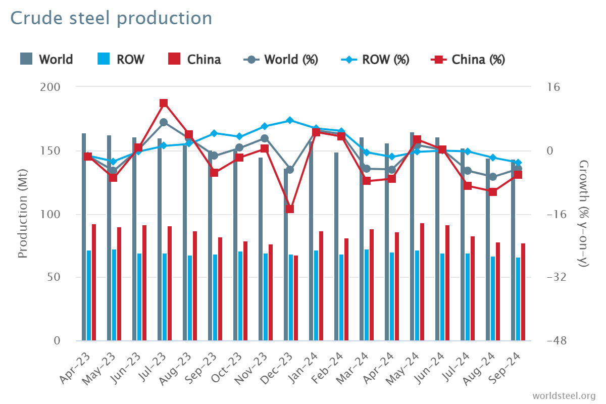
Produksi Baja Mentah pada September 2024

Pada bulan September 2024, produksi baja mentah dunia untuk 71 negara yang melaporkan kepada Asosiasi Baja Dunia (baja dunia) adalah 143,6 juta ton (Mt), turun 4,7% dari September 2023.

produksi baja mentah

produksi baja mentah

Produksi baja mentah menurut wilayah

Afrika memproduksi 1,9 juta ton pada September 2024, naik 2,6% dari September 2023. Asia dan Oseania memproduksi 105,3 juta ton, turun 5,0%. Uni Eropa (27) memproduksi 10,5 juta ton, naik 0,3%. Eropa dan negara-negara lain memproduksi 3,6 juta ton, naik 4,1%. Timur Tengah memproduksi 3,5 juta ton, turun 23,0%. Amerika Utara memproduksi 8,6 juta ton, turun 3,4%. Rusia & negara-negara CIS lainnya + Ukraina memproduksi 6,8 juta ton, turun 7,6%. Amerika Selatan memproduksi 3,5 juta ton, naik 3,3%.

Tabel 1. Produksi baja mentah menurut wilayah

Wilayah September 2024 (Mt) % berubah 24/23 Sep Januari-September 2024 (Mt) % berubah 24/23 Jan-Sep
Afrika 1.9 2.6 16.6 2.3
Asia dan Oseania 105.3 -5 1,032.00 -2.5
Uni Eropa (27) 10.5 0.3 97.8 1.5
Eropa, Lainnya 3.6 4.1 33.1 7.8
Timur Tengah 3.5 -23 38.4 -1.5
Amerika Utara 8.6 -3.4 80 -3.9
Rusia & CIS lainnya + Ukraina 6.8 -7.6 64.9 -2.5
Amerika Selatan 3.5 3.3 31.4 0
Jumlah 71 negara 143.6 -4.7 1,394.10 -1.9

Ke-71 negara yang termasuk dalam tabel ini menyumbang sekitar 98% dari total produksi baja mentah dunia pada tahun 2023.

Wilayah dan negara yang tercakup dalam tabel:

  • Afrika: Aljazair, Mesir, Libya, Maroko, Afrika Selatan, Tunisia
  • Asia dan Oseania: Australia, Tiongkok, India, Jepang, Mongolia, Selandia Baru, Pakistan, Korea Selatan, Taiwan (Tiongkok), Thailand, Vietnam
  • Uni Eropa (27): Austria, Belgia, Bulgaria, Kroasia, Republik Ceko, Finlandia, Prancis, Jerman, Yunani, Hungaria, Italia, Luksemburg, Belanda, Polandia, Portugal, Rumania, Slowakia, Slovenia, Spanyol, Swedia
  • Eropa, Lainnya: Makedonia, Norwegia, Serbia, Turki, Inggris Raya
  • Timur Tengah: Bahrain, Iran, Irak, Yordania, Kuwait, Oman, Qatar, Arab Saudi, Uni Emirat Arab, Yaman
  • Amerika Utara: Kanada, Kuba, El Salvador, Guatemala, Meksiko, Amerika Serikat
  • Rusia & negara CIS lainnya + Ukraina: Belarus, Kazakhstan, Rusia, Ukraina
  • Amerika Selatan: Argentina, Brasil, Chili, Kolombia, Ekuador, Paraguay, Peru, Uruguay, Venezuela

10 negara penghasil baja teratas

Tiongkok memproduksi 77,1 juta ton pada September 2024, turun 6,11 juta ton dari September 2023. India memproduksi 11,7 juta ton, turun 0,21 juta ton. Jepang memproduksi 6,6 juta ton, turun 5,81 juta ton. Amerika Serikat memproduksi 6,7 juta ton, naik 1,21 juta ton. Rusia diperkirakan memproduksi 5,6 juta ton, turun 10,31 juta ton. Korea Selatan memproduksi 5,5 juta ton, naik 1,31 juta ton. Jerman memproduksi 3,0 juta ton, naik 4,31 juta ton. Turki memproduksi 3,1 juta ton, naik 6,51 juta ton. Brasil memproduksi 2,8 juta ton, naik 9,91 juta ton. Iran diperkirakan memproduksi 1,5 juta ton, turun 41,21 juta ton.

Tabel 2. 10 negara penghasil baja teratas

Wilayah  September 2024 (Mt) % berubah 24/23 Sep Januari-September 2024 (Mt) % berubah 24/23 Jan-Sep
Cina 77.1 -6.1 768.5 -3.6
India 11.7 -0.2 110.3 5.8
Jepang 6.6 -5.8 63.3 -3.2
Amerika Serikat 6.7 1.2 60.3 -1.6
Rusia 5.6 dan -10.3 54 -5.5
Korea Selatan 5.5 1.3 48.1 -4.6
Jerman 3 4.3 28.4 4
Turki 3.1 6.5 27.9 13.8
Brazil 2.8 9.9 25.2 4.4
Bahasa Indonesia:Iran 1,5 tahun -41.2 21.3 -3.1

e – estimasi. Peringkat 10 negara penghasil teratas didasarkan pada agregat tahun berjalan

API 5L vs. ISO 3183

Ketahui Perbedaannya: API 5L vs ISO 3183

ISO 3183 dan API 5L adalah standar yang terkait dengan pipa baja, terutama untuk digunakan dalam industri minyak, gas, dan transportasi fluida lainnya. Meskipun terdapat banyak kesamaan antara kedua standar ini, API 5L vs ISO 3183, terdapat perbedaan utama dalam cakupan, aplikasi, dan organisasi di baliknya.

1. Organisasi Penerbit: API 5L vs ISO 3183

API 5L: Diterbitkan oleh American Petroleum Institute (API), standar ini terutama digunakan dalam industri minyak dan gas. Standar ini merinci persyaratan teknis untuk pipa baja yang mengangkut minyak, gas, dan air.
ISO 3183: Dikeluarkan oleh Organisasi Internasional untuk Standardisasi (ISO), standar ini diakui secara internasional dan digunakan secara global untuk pipa baja di sektor transportasi minyak dan gas.

2. Ruang Lingkup Aplikasi: API 5L vs ISO 3183

API 5L: Meliputi pipa baja untuk mengangkut minyak bumi, gas alam, dan cairan lain di bawah tekanan tinggi. Pipa ini banyak digunakan di Amerika Utara, terutama di Amerika Serikat.
ISO 3183: Standar ini terutama berfokus pada desain, pembuatan, dan kontrol kualitas pipa baja yang digunakan dalam pipa minyak dan gas, tetapi penggunaannya lebih internasional dan berlaku di berbagai negara di seluruh dunia.

3. Perbedaan Utama: API 5L vs ISO 3183

Fokus Geografis dan Pasar:

API 5L lebih disesuaikan untuk pasar Amerika Utara (khususnya AS), sementara ISO 3183 berlaku secara internasional dan digunakan di banyak negara di seluruh dunia.

Mutu dan Persyaratan Baja:

API 5L mendefinisikan mutu baja seperti L175, L210, L245, dan seterusnya, di mana angka tersebut melambangkan kekuatan luluh minimum dalam megapascal (MPa).
ISO 3183 juga mendefinisikan tingkatan serupa tetapi dengan persyaratan lebih rinci mengenai sifat material, proses manufaktur, dan protokol pemeriksaan, yang selaras dengan praktik industri internasional.
Spesifikasi Tambahan:
API 5L menekankan kontrol kualitas, sertifikasi, dan persyaratan produksi, sedangkan ISO 3183 mencakup cakupan yang lebih luas, dengan mempertimbangkan perdagangan internasional, dan menyediakan spesifikasi untuk berbagai kondisi, termasuk suhu, lingkungan, dan persyaratan mekanis khusus.

4. Persyaratan Teknis: API 5L vs ISO 3183

API 5L menetapkan sifat material pipa baja, proses produksi, dimensi, metode pengujian, dan kontrol kualitas. Standar ini menetapkan mutu baja dari L (kekuatan rendah) hingga mutu X (kekuatan lebih tinggi), seperti X42, X60, dan X70.
ISO 3183 mencakup aspek serupa dari pembuatan pipa baja, termasuk kualitas material, perlakuan panas, perlakuan permukaan, dan ujung pipa. Standar ini juga menyediakan spesifikasi terperinci untuk tekanan desain pipa, pertimbangan lingkungan, dan berbagai aksesori pipa.

5. Perbandingan Mutu Pipa: API 5L vs ISO 3183

API 5L: Mutu berkisar dari mutu L (kekuatan luluh rendah) hingga mutu X (kekuatan luluh lebih tinggi). Misalnya, X60 mengacu pada pipa dengan kekuatan luluh 60.000 psi (sekitar 413 MPa).
ISO 3183: Menggunakan sistem penilaian yang serupa tetapi mungkin mencakup klasifikasi dan ketentuan yang lebih rinci. Standar ini juga memastikan keselarasan dengan desain jaringan pipa global dan praktik operasional.

6. Kompatibilitas Antar Standar:

Dalam banyak kasus, API 5L dan ISO 3183 kompatibel, artinya pipa baja yang memenuhi persyaratan API 5L pada umumnya juga akan memenuhi persyaratan ISO 3183 dan sebaliknya. Namun, proyek pipa tertentu mungkin mematuhi satu standar di atas yang lain, tergantung pada lokasi, preferensi klien, atau persyaratan peraturan.

7. Kesimpulan:

API 5L lebih umum di Amerika Serikat dan wilayah sekitarnya. API ini berfokus pada industri pipa minyak dan gas, yang sangat menekankan produksi dan kontrol kualitas.
ISO 3183 adalah standar internasional untuk proyek jaringan pipa minyak dan gas global. Persyaratannya yang lebih rinci dan selaras secara global memastikan penerimaan yang lebih luas di pasar internasional.

Kedua standar tersebut sangat mirip dalam hal spesifikasi material, manufaktur, dan pengujian. Namun, ISO 3183 cenderung memiliki cakupan yang lebih luas dan lebih dapat diterapkan secara global, sementara API 5L tetap lebih spesifik untuk pasar Amerika Utara. Pilihan antara standar-standar ini bergantung pada lokasi geografis, spesifikasi, dan kebutuhan regulasi proyek pipa.