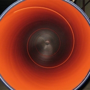
3LPE Coated Line Pipes

Successfully Delivered a Batch of Submarine Pipeline Orders for Transporting Gasoline

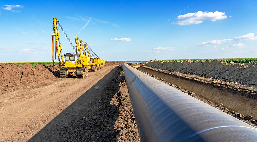
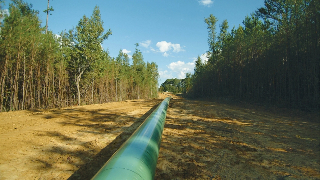
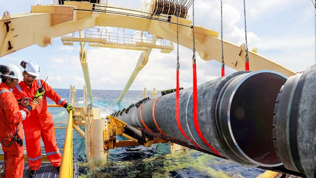
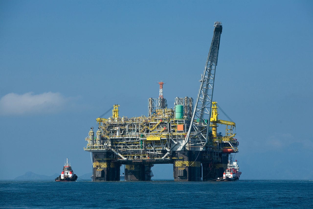
After a month of intense efforts, our company successfully delivered the subsea oil and gas pipeline order. The successful delivery of this order proved the dedication and expertise of our sales and production teams, despite the harsh meteorological conditions, such as typhoons, encountered during the transport. The order involves the construction of a high-quality and high-standard submarine pipeline project, and the goods will be used in constructing submarine pipelines for oil terminals to connect oil tankers and on-shore storage tanks, aiming at safely transporting oil and gas under the sea.

The specifications of the order are as follows:

  • Outer coating: three-layer polyethylene coating
  • Coating thickness: 2.7mm
  • Coating standard: DIN 30670-2012 N-v
  • Base pipe standard and material: API Spec 5L Grade B
  • Base pipe type: Seamless
  • Size: NPS 6″ & 8″ x SCH40 x 11.8M
  • Other items: NPS 6″ & 8″ x SCH40 SORF and WNRF flanges, 90° 5D elbows, 90° long radius elbows, bolts and nuts.
3LPE Coated API 5L Gr.B Line Pipes, 90° Pipe Bends, 90° LR Elbows, SO, BL, WN Flanges,Bolt & Nuts

3LPE Coated API 5L Gr.B Line Pipes, 90° Pipe Bends, 90° LR Elbows, SORF, WNRF Flanges, Bolt & Nuts

We produce the pipes according to API Spec 5L, the anti-corrosion coating according to DIN 30670-2012, the 90° 5D elbows according to ASME B16.49, ISO 15590-1, EN 14870-1, the 90° long radius elbows according to ASME B16.9, and the flanges according to ASME B16.5 to ensure the pipework met the highest safety and performance standards.

Everything is full of uncertainties and interludes, and a happy ending is the ultimate quest. We are proud of our team’s hard work and dedication and look forward to continuing to push the boundaries of the energy infrastructure sector and new pipeline projects.

If you have RFQs about a subsea pipeline project or require high-quality 3LPE/3LPP/FBE/LE anti-corrosion pipelines, please feel free to contact us at [email protected], where our team will provide you with reliable solutions and one-stop services.

Stainless Steel vs Galvanized Steel

Stainless Steel vs Galvanised Steel

Introduction

Stainless Steel vs Galvanized Steel, it’s crucial to consider the environment, required durability, and maintenance needs. Stainless steel offers unmatched corrosion resistance, strength, and visual appeal, making it suitable for demanding applications in harsh environments. Galvanized steel, on the other hand, offers cost-effective corrosion protection for less aggressive settings.

1. Composition and Manufacturing Process

Stainless Steel

Stainless steel is an alloy composed mainly of iron, chromium (at least 10.5%), and sometimes nickel and molybdenum. Chromium forms a protective oxide layer on the surface, giving it excellent corrosion resistance. Different grades, like 304 and 316, vary in alloying elements, providing options for various environments, including extreme temperatures and high salinity.

Galvanized Steel

Galvanized steel is carbon steel coated with a layer of zinc. The zinc layer protects the steel underneath as a barrier against corrosion. The most common galvanizing method is hot-dip galvanizing, where the steel is submerged in molten zinc. Another method is electro-galvanizing, where zinc is applied using an electric current. Both processes enhance corrosion resistance, though they are generally less durable in harsh environments than stainless steel.

2. Corrosion Resistance

Stainless Steel

Stainless steel’s corrosion resistance is inherent due to its alloy composition, which forms a passive chromium oxide layer. Grade 316 stainless steel, which includes molybdenum, provides excellent resistance to corrosion from chlorides, acids, and other aggressive chemicals. It’s a preferred choice in marine, chemical processing, and oil and gas industries, where exposure to corrosive agents is daily.

Galvanized Steel

The zinc layer on galvanized steel provides sacrificial protection; the zinc will corrode before the underlying steel, offering some corrosion resistance. However, this protection is limited, as the zinc layer can degrade over time. While galvanized steel performs adequately in mild environments and general construction, it doesn’t withstand harsh chemicals or saltwater exposure as effectively as stainless steel.

3. Mechanical Properties and Strength

Stainless Steel

Stainless steel is generally more robust than galvanized steel, with higher tensile strength and durability. This makes it ideal for applications that require resilience and reliability under pressure. Stainless steel also offers excellent resistance to impact and wear, which benefits infrastructure and heavy-duty industrial applications.

Galvanized Steel

While galvanized steel’s strength primarily comes from the carbon steel core, it is generally less robust than stainless steel. The added zinc layer doesn’t significantly contribute to its strength. Galvanized steel is suitable for medium-duty applications where corrosion resistance is necessary but not in extreme or high-stress environments.

4. Appearance and Aesthetics

Stainless Steel

Stainless steel has a sleek, shiny appearance and is often desirable in architectural applications and visible installations. Its aesthetic appeal and durability make it a preferred choice for high-visibility structures and equipment.

Galvanized Steel

The zinc layer gives galvanized steel a dull, matte-gray finish less visually appealing than stainless steel. Over time, exposure to weather may lead to a whitish patina on the surface, which can reduce aesthetic appeal, though it doesn’t impact performance.

5. Cost Considerations

Stainless Steel

Stainless steel is typically more expensive due to its alloying elements, chromium and nickel, and complex manufacturing processes. However, its longer lifespan and minimal maintenance can offset the initial cost, especially in demanding environments.

Galvanized Steel

Galvanized steel is more economical than stainless steel, especially for short- to medium-term applications. It’s a cost-effective choice for projects with a limited budget and moderate corrosion resistance needs.

6. Typical Applications

Stainless Steel Applications

Oil and Gas: Used in pipelines, storage tanks, and offshore platforms due to its high corrosion resistance and strength.
Chemical Processing: Excellent for environments where exposure to acidic or caustic chemicals is every day.
Marine Engineering: Stainless steel’s resistance to saltwater makes it suitable for marine applications like docks, vessels, and equipment.
Infrastructure: Ideal for bridges, railings, and architectural structures where durability and aesthetics are essential.

Galvanized Steel Applications

General Construction: Commonly used in building frames, fences, and roofing supports.
Agricultural Equipment: Provides a balance of corrosion resistance and cost-effectiveness for equipment exposed to soil and moisture.
Water Treatment Facilities: Suitable for non-critical water infrastructure, such as piping and storage tanks in low-corrosion environments.
Outdoor Structures: Commonly used in road barriers, guardrails, and poles, where exposure to mild weather conditions is expected.

7. Maintenance and Longevity

Stainless Steel

Stainless steel requires minimal maintenance due to its inherent corrosion resistance. However, in harsh environments, periodic cleaning is recommended to remove salt, chemicals, or deposits that could compromise the protective oxide layer over time.

Galvanized Steel

Galvanized steel requires regular inspection and maintenance to keep the zinc layer intact. If the zinc layer is scratched or degraded, re-galvanizing or additional coatings may be necessary to prevent corrosion. This is particularly important in marine or industrial applications, where the zinc layer is at risk of degrading faster.

8. Example: Stainless Steel vs Galvanized Steel

PROPERTY STAINLESS STEEL (316) GALVANISED STEEL COMPARISON
Mechanism of protection A protective oxide layer that self-repairs in the presence of oxygen, granting long-term corrosion resistance. A protective zinc coating is applied to the steel during manufacturing. When damaged, surrounding zinc cathodically protects the exposed steel. The stainless steel protective layer is more durable and can ‘heal’ itself. Stainless steel protection does not diminish with material loss or thickness reduction.
Appearance Many finishes are available, from very bright electropolished to abrasive linished. Appealing high-quality look and feel. Spangles possible. The surface is not bright and gradually changes to a dull grey with age. Aesthetic design choice.
Surface feel It is very smooth and can be slippery. It has a coarser feel, which becomes more apparent with age. Aesthetic design choice.
Green credentials It may be reused in new structures. After the lifetime of the structure, it is valuable as scrap, and because of its collection value, it has a high recycling rate. Carbon steel is generally scrapped at end-of-life and is less valuable. Stainless steel is extensively recycled both within manufacturing and at end-of-life. All new stainless steel contains a substantial proportion of recycled steel.
Heavy metal runoff Negligible levels. Significant zinc runoff off, especially early in life. Some European highways have been changed to stainless steel railings to avoid environmental zinc contamination.
Lifetime Indefinite, provided surface is maintained. Slow general corrosion until the zinc dissolves. Red rust will appear as the zinc/iron layer corrodes, and finally, the substrate steel. Repair is required before ~2% of the surface has red spots. Clear life-cycle cost benefit for stainless steel if extended life intended. The economic break-even point can be as short as six years, depending on the environment and other factors.
Fire resistance Excellent for austenitic stainless steels with reasonable strength and deflection during fires. Zinc melts and runs, which may cause the failure of adjacent stainless steel in a chemical plant. The carbon steel substrate loses strength and suffers deflection. Stainless steel offers better fire resistance and avoids the risk of molten zinc if galvanised is used.
Welding on site This is a routine for austenitic stainless steels, with care about thermal expansion. Welds can be blended into the surrounding metal surface. Post-weld clean-up and passivation are essential. Carbon steel is readily self-weldable, but zinc must be removed because of fumes. If galvanised and stainless steel are welded together, any zinc residue will embrittle the stainless steel. Zinc-rich paint is less durable than galvanizing. In severe marine environments, crusty rust can appear in three to five years, and steel attacks occur at four years/mm afterward. Short-term durability is similar, but a zinc-rich coating at joins requires upkeep. In severe conditions, galvanized steel will get rough rust—even holes—and possible hand injury, especially from the unseen seaward side.
Contact with damp, porous material (e.g., wooden wedges) in a salty environment. It will likely cause rust stains and crevice attack but not structural failure. Similar to storage stains, it leads to rapid zinc loss and longer-term due to perforation. It is not desirable for either, but it can cause failure at the base of galvanized poles in the long term.
Maintenance It can suffer from tea staining and micro-pitting if not adequately maintained. It can suffer general zinc loss and subsequent corrosion of the steel substrate if not adequately maintained. Rain in open areas or washing in sheltered regions is required for both.
ASTM A335 ASME SA335 P92 SMLS PIPE

Microstructure Evolution of P92 Steel at Different Isothermal Temperatures

Microstructure Evolution of P92 Steel at Different Isothermal Temperatures

P92 steel is mainly used in ultra-supercritical boilers, ultra-high-pressure pipelines, and other high-temperature and high-pressure equipment.P92 steel is in the P91 steel chemical composition based on the addition of trace elements of W and B elements, reduces the content of Mo, through the grain boundaries of the strengthened and dispersion strengthened in a variety of ways, to improve the comprehensive performance of the P92 steel, P92 steel than the P91 steel has better resistance to oxidation performance and corrosion resistance. A hot working process is essential for producing the P92 steel pipe. Thermal processing technology can eliminate the internal defects generated in the production process and make the steel performance meet the needs of working conditions. The type and state of the organization in the hot working process are the key factors influencing the performance to meet the standard. Therefore, this paper analyzes the organization of P92 steel pipe at different isothermal temperatures to reveal the organization evolution of P92 steel pipe at various temperatures, which not only provides information support for the organization analysis and performance control of the actual hot working process but also lays the experimental basis for the development of the hot working process.

1. Test Materials and Methods

1.1 Test Material

The tested steel is a P92 steel pipe in use condition (1060 ℃ hardened + 760 ℃ tempered), and its chemical composition is shown in Table 1. A cylindrical specimen of ϕ4 mm × 10 mm was cut in the middle part of the finished pipe at a particular position along the length direction, and the quenching expansion meter was used to study the tissue transformation at different temperatures.

Table 1 Main Chemical Composition of P92 Steel by Mass Fraction (%)

Element C Si Mn Cr Ni Mo V Al B Nb W Fe
% 0.13 0.2 0.42 8.67 0.25 0.48 0.19 0.008 0.002 0.05 1.51 Balance

1.2 Test Process

Using L78 quenching thermal expansion meter, 0.05 ℃ / s warming up to 1050 ℃ insulation 15min, 200 ℃ / s cooling down to room temperature. Measure the critical point of phase change of the material Ac1 is 792.4℃, Ac3 is 879.8℃, Ms is 372.3℃. The specimens were heated up to 1050°C at a rate of 10°C/s and held for 15 min, and then cooled down to different temperatures (770, 740, 710, 680, 650, 620, 520, 430, 400, 370, 340, 310, 280, 250, 190, and 160°C) at a rate of 150°C/s and held for different periods of time (620°C and below for 1h, 620°C and above for 25h). 620 ℃ and above holding 25h), the isothermal end of the power is off so that the specimen is air-cooled to room temperature.1.3 Test methods

After grinding and polishing the surface of the specimens under different processes, the surface of the specimens was corroded using aqua regia. AXIOVERT 25 Zeiss microscope and QWANTA 450 environmental scanning electron microscope were used to observe and analyze the organization; using HVS-50 Vickers hardness tester (load weight of 1kg), hardness measurements were made at several locations on the surface of each specimen and the average value was taken as the hardness value of the specimen.

2. Test Results and Analysis

2.1 Organization and Analysis of Different Isothermal Temperature

Figure 1 shows the microstructure of P92 steel after complete austenitization at 1050°C for different times at different temperatures. Figure 1(a) shows the microstructure of P92 steel after isothermalization at 190℃ for 1h. From Fig. 1(a2), it can be seen that its room temperature organization is martensite (M). From Fig. 1(a3 ), it can be seen that the martensite shows lath-like characteristics. Since the Ms point of the steel is about 372°C, the martensite phase transformation occurs at isothermal temperatures below the Ms point, forming martensite, and the carbon content of the P92 steel belongs to the range of low carbon compositions; a lath-like morphology characterizes the martensite.

Figure 1(a) shows the microstructure of P92 steel after 1h isothermal at 190°C

Figure 1(a) shows the microstructure of P92 steel after 1h isothermal at 190°C

Figure 1(b) for the microstructure of P92 steel at 430 ℃ isothermal 1h. As the isothermal temperature increases to 430°C, P92 steel reaches the bainite transformation zone. Since the steel contains Mo, B, and W elements, these elements have little effect on the bainite transformation while delaying the pearlitic transformation. Therefore, P92 steel at 430 ℃ insulation 1h, the organization of a certain amount of bainite. Then the remaining supercooled austenite is transformed into martensite when air-cooled.

Figure 1(b) for the microstructure of P92 steel at 430 ℃ isothermal 1h

Figure 1(b) for the microstructure of P92 steel at 430 ℃ isothermal 1h

Figure 1(c) shows the microstructure of P92 steel at 520 ℃ isothermal 1h. When the isothermal temperature of 520 ℃, the alloying elements Cr, Mo, Mn, etc., so that the pearlite transformation is inhibited, the start of the bainite transformation point (Bs point) is reduced, so in a specific range of temperatures will appear in the stabilization zone of the supercooled austenite. Figure 1(c) can be seen in 520 ℃ insulation 1h after supercooled austenite did not occur after the transformation, followed by air cooling to form martensite; the final room temperature organization is the martensite.

Figure 1(c) shows the microstructure of P92 steel at 520 ℃ isothermal 1h

Figure 1(c) shows the microstructure of P92 steel at 520 ℃ isothermal 1h

Figure 1 (d) for the P92 steel at 650 ℃ isothermal 25h microstructure for martensite + pearlite. As shown in Figure 1(d3), pearlite shows discontinuous lamellar characteristics, and the carbide on the surface shows a short rod precipitation. This is due to the P92 steel alloying elements Cr, Mo, V, etc. to improve the stability of supercooled austenite at the same time so that the P92 steel pearlite morphology changes, that is, the carbide in the pearlitic body of the carbide for the short rod, this pearlitic body is known as the class pearlite. At the same time, many fine second-phase particles were found in the organization.

Figure 1 (d) for the P92 steel at 650 ℃ isothermal 25h microstructure for martensite + pearlite

Figure 1 (d) for the P92 steel at 650 ℃ isothermal 25h microstructure for martensite + pearlite

Figure 1(e) shows the microstructure of P92 steel at 740 ℃ isothermal 25h. At 740°C isothermal, there will be first eutectic massive ferrite precipitation and then austenite eutectic decomposition, resulting in pearlite-like organization. Compared with the 650°C isothermal (see Fig. 1(d3)), the pearlitic organization becomes coarser as the isothermal temperature is increased, and the two-phase character of pearlite, i.e., ferrite and carburite in the form of a short bar, is clearly visible.

Figure 1(e) shows the microstructure of P92 steel at 740 ℃ isothermal 25h

Figure 1(e) shows the microstructure of P92 steel at 740 ℃ isothermal 25h

Fig. 1(f) shows the microstructure of P92 steel at 770°C isothermal temperature for 25h. At 770°C isothermal, with the extension of the isothermal time, the precipitation of ferrite occurs first, and then the supercooled austenite undergoes eutectic decomposition to form a ferrite + pearlite organization. With the increase of isothermal temperature, the first eutectic ferrite content increases, and the pearlite content decreases. Because of the P92 steel alloying elements, alloying elements dissolved into the austenite to make the austenite hardenability increase, the difficulty of the eutectic decomposition becomes more extensive, so there must be a sufficiently long isothermal time to make its eutectic decomposition, the formation of the pearlitic organization.

Fig. 1(f) shows the microstructure of P92 steel at 770°C isothermal temperature for 25h

Fig. 1(f) shows the microstructure of P92 steel at 770°C isothermal temperature for 25h

Energy spectrum analysis was performed on the tissues with different morphologies in Fig. 1(f2) to identify the tissue type further, as shown in Table 2. From Table 2, it can be seen that the carbon content of the white particles is higher than other organizations, and the alloying elements Cr, Mo, and V are more, analyzing this particle for the composite carbide particles precipitated during the cooling process; comparatively speaking, the carbon content in the discontinuous lamellar organization is second to the lowest, and the carbon content in the massive organization is the least. Because pearlite is a two-phase organization of carburize and ferrite, the average carbon content is higher than that of ferrite; combined with isothermal temperature and morphology analysis, it is further determined that the lamellar organization is pearlite-like, and the massive organization is first eutectic ferrite.

Spectrum Analysis Of The P92 Steel, Isothermally Treated At 770 °C For 25 Hours, Written In Table Format With Atom Fractions (%)

Structure C Nb Mo Ti V Cr Mn Fe W
White Granules 11.07 0.04 0.94 0.02 2.16 8.36 2.64 54.77 2.84
Block Structure 9.31 0.04 0.95 0.2 0.32 8.42 0.74 85.51 10.21
Layered Structure 5.1 0 0.09 0.1 0.33 7.3 0.35 85.65 0.69

2.2 Microhardness and Analysis

Generally speaking, during the cooling process of alloy steels containing elements such as W and Mo, three kinds of organizational transformations occur in the supercooled austenite: martensitic transformation in the low-temperature zone, bainite transformation in the medium-temperature zone, and pearlite transformation in the high-temperature zone. The different organizational evolutions lead to different hardnesses. Figure 2 shows the variation of the hardness curve of P92 steel at different isothermal temperatures. From Fig. 2, it can be seen that with the increase of isothermal temperature, the hardness shows the trend of decreasing first, then increasing, and finally decreasing. When the isothermal temperature of 160 ~ 370 ℃, the occurrence of martensitic transformation, Vickers hardness from 516HV to 457HV. When the isothermal temperature is 400 ~ 620 ℃, a small amount of bainite transformation occurs, and the hardness of 478HV increases to 484HV; due to the small bainite transformation, the hardness does not change much. When the isothermal temperature is 650 ℃, a small amount of pearlite forms, with a hardness of 410HV. when the isothermal temperature of 680 ~ 770 ℃, the formation of ferrite + pearlite organization, hardness from 242HV to 163HV. due to the transformation of P92 steel at different temperatures in the organization of the transition is different, in the region of the low-temperature martensitic transformation, when the isothermal temperature is lower than the point of Ms, with the increase in temperature, martensite content decreases, hardness decreases; in the middle of the transformation of P92 steel in the different temperatures, when the isothermal temperature is lower than the Ms point, with the temperature increase, martensitic content decreases, the hardness decreases; in the medium-temperature bainite transformation region, because the amount of bainite transformation is small, the hardness does not change much; in the high-temperature pearlitic transformation region, with the rise of isothermal temperature, the first eutectic ferrite content increases so that the hardness continues to decline, so with the increase in isothermal temperature, the material hardness is generally a decreasing trend, and the trend of the change in hardness and the analysis of the organization is in line with the trend.

Variation Of Hardness Curves Of P92 Steel At Different Isothermal Temperatures

Variation Of Hardness Curves Of P92 Steel At Different Isothermal Temperatures

3. Conclusion

1) The critical point Ac1 of P92 steel is 792.4 ℃, Ac3 is 879.8 ℃, and Ms is 372.3 ℃.

2) P92 steel at different isothermal temperatures to obtain the room temperature organization is different; in the 160 ~ 370 ℃ isothermal 1h, the room temperature organization is martensite; in the 400 ~ 430 ℃ isothermal 1h, the organization of a small amount of bainite + martensite; in the 520 ~ 620 ℃ isothermal 1h, the organization is relatively stable, a short period of time (1 h) does not occur within the transformation, the room temperature organization is martensite; in the 650 ℃ isothermal 25h, the room temperature organization is pearlite. h, room temperature organization for pearlite + martensite; in 680 ~ 770 ℃ isothermal 25h, the organization transformed into pearlite + first eutectic ferrite.

3) P92 steel austenitization in Ac1 below isothermal, with the reduction of isothermal temperature, the hardness of the material as a whole tends to increase, isothermal at 770 ℃ after the occurrence of the first eutectic ferrite precipitation, pearlitic transformation, hardness is the lowest, about 163HV; isothermal at 160 ℃ after the occurrence of the martensitic transformation, hardness is the highest, about 516HV.

ASME B31.3 vs ASME B31.1

ASME B31.1 vs. ASME B31.3: Know the Piping Design Codes

Introduction

In piping design and engineering, selecting the appropriate piping code is essential for ensuring safety, efficiency, and compliance with industry standards. Two of the most widely recognized piping design codes are ASME B31.1 and ASME B31.3. While they both come from the American Society of Mechanical Engineers (ASME) and govern the design and construction of piping systems, their applications differ significantly. Understanding the ASME B31.1 vs. ASME B31.3 debate is crucial for selecting the correct code for your project, whether it involves power plants, chemical processing, or industrial facilities.

Overview: ASME B31.1 vs. ASME B31.3

What is ASME B31.3 or Process Piping Code?

ASME B31.1 is the standard that governs the design, construction, and maintenance of power plant piping systems. It applies to piping systems in power plants, industrial plants, and other facilities where power generation is involved. This code focuses heavily on the integrity of systems that handle high-pressure steam, water, and hot gases.

Typical Applications: Power plants, heating systems, turbines, and boiler systems.
Pressure Range: High-pressure steam and fluid systems.
Temperature Range: High-temperature service, especially for steam and gas applications.

What is ASME B31.1 or Power Piping Code?

ASME B31.3 applies to the design and construction of piping systems used in chemical, petrochemical, and pharmaceutical industries. It governs systems that transport chemicals, gases, or liquids under different pressure and temperature conditions, often including hazardous materials. This code also covers the associated support systems and the safety considerations of handling chemicals and dangerous substances.

Typical Applications: Chemical processing plants, refineries, pharmaceutical facilities, food and beverage plants.
Pressure Range: Generally lower than the pressure range in ASME B31.1, depending on fluid types and their classification.
Temperature Range: varies depending on the chemical fluids, but it is typically lower than the extreme conditions in ASME B31.1.

Difference Between ASME B31.3 and ASME B31.1 (ASME B31.3 vs ASME B31.1)

ASME B31.3 vs ASME B31.1

ASME B31.3 vs ASME B31.1

Sr No Parameter ASME B31.3-Process Piping ASME B31.1-Power Piping
1 Scope Provides rules for Process or Chemical Plants Provides rules for Power Plants
2 Basic Allowable Material Stress Basic allowable material stress value is higher (For example the allowable stress value for A 106 B material at 250 Deg C is 132117.328 Kpa as per ASME B31.3) Basic allowable material stress value is lower (For example the allowable stress value for A 106 B material at 250 Deg C is 117900.344 Kpa as per ASME B31.3)
3 Allowable Sagging (Sustained) The ASME B31.3 code does not specifically limit allowable sagging. An allowable sagging of up to 15 mm is generally acceptable. ASME B31.3 does not provide a suggested support span. ASME B31.1 clearly specifies the allowable sagging value as 2.5 mm. Table 121.5-1 of ASME B31.1 provides suggested support span.
4 SIF on Reducers Process Piping Code ASME B31.3 does not use SIF (SIF=1.0) for reducer stress calculation Power Piping code ASME B31.1 uses a maximum SIF of 2.0 for reducers while stress calculation.
5 Factor of Safety ASME B31.3 uses a factor of safety of 3; relatively lower than ASME B31.1. ASME B31.1 uses a safety factor of 4 to have higher reliability as compared to Process plants
6 SIF for Butt Welded Joints ASME B31.3 uses a SIF of 1.0 for buttwelded joints ASME B31.1 uses a SIF of up to 1.9 max in stress calculation.
7 Approach towards SIF ASME B31.3 uses a complex in-plane, out-of-plane SIF approach. ASME B31.1 uses a simplified single SIF Approach.
8 Maximum values of Sc and Sh As per the Process Piping code, the maximum value of Sc and Sh are limited to 138 Mpa or 20 ksi. For the Power piping code, the maximum value of Sc and Sh are 138 Mpa only if the minimum tensile strength of the material is 70 ksi (480Mpa); otherwise, it depends on the values provided in the mandatory appendix A as per temperature.
9 Allowable Stress for Occasional Stresses The allowable value of occasional stress is 1.33 times Sh As per ASME B31.1, the allowable value of occasional stress is 1.15 to 1.20 times Sh
10 The equation for Pipe Wall Thickness Calculation The equation for pipe wall thickness calculation is valid for t<D/6 There is no such limitation in the Power piping wall thickness calculation. However, they add a limitation on maximum design pressure.
11 Section Modulus, Z for Sustained and Occasional Stresses While Sustained and Occasional stress calculation the Process Piping code reduces the thickness by corrosion and other allowances. ASME B31.1 calculates the section modulus using nominal thickness. Thickness is not reduced by corrosion and other allowances.
12 Rules for material usage below -29 Deg. C ASME B31.3 provides extensive rules for the use of materials below -29 degrees C The power piping code provides no such rules for pipe materials below -29 degrees C.
13 Maximum Value of Cyclic Stress Range Factor The maximum value of cyclic stress range factor f is 1.2 The maximum value of is 1.0
14 Allowance for Pressure Temperature Variation As per clause 302.2.4 of ASME B31.3, occasional pressure temperature variation can exceed the allowable by (a) 33% for no more than 10 hours at any one time and no more than 100 hours/year, or (b) 20% for no more than 50 hours at any one time and no more than 500 hours/year. As per clause 102.2.4 of ASME B31.1, occasional pressure temperature variation can exceed the allowable by (a) 15% if the event duration occurs for no more than 8 hours at any one time and not more than 800 hours/year or (b) 20% if the event duration occurs for not more than 1 hour at any one time and not more than 80 hour/year.
15 Design Life Process Piping is normally designed for 20 to 30 years of service life. Power Piping is generally designed for 40 years or more of service life.
16 PSV reaction force ASME B31.3 does not provide specific equations for PSV reaction force calculation. ASME B31.1 provides specific equations for PSV reaction force calculation.

Conclusion

The critical difference in the ASME B31.1 vs. ASME B31.3 debate lies in the industry applications, material requirements, and safety considerations. ASME B31.1 is ideal for power generation and high-temperature systems, focusing on mechanical integrity. At the same time, ASME B31.3 is tailored for the chemical and process industries, emphasizing the safe handling of hazardous materials and chemical compatibility. By understanding the distinctions between these two standards, you can decide which code best suits your project’s requirements, ensuring compliance and safety throughout the project’s lifecycle. Whether you are involved in power plant design or system’ processing, choosing the correct piping code is crucial for a successful project.

ASME BPVC Section II Part A

ASME BPVC Section II Part A: Ferrous Material Specifications

Introduction

ASME BPVC Section II Part A: Ferrous Material Specifications is a section of the ASME Boiler and Pressure Vessel Code (BPVC) that covers specifications for ferrous materials (primarily iron) used in the construction of boilers, pressure vessels and other pressure-retaining equipment. This section specifically addresses the requirements for steel and iron materials, including carbon steel, alloy steel, and stainless steel.

Related Material Specifications for Tubes & Plates

Tubes:

SA-178/SA-178M – Electric-Resistance-Welded Carbon Steel and Carbon-Manganese Steel Boiler and Superheater Tubes
SA-179/SA-179M – Seamless Cold-Drawn Low-Carbon Steel Heat-Exchanger and Condenser Tubes
SA-192/SA-192M – Seamless Carbon Steel Boiler Tubes for High-Pressure Service
SA-209/SA-209M – Seamless Carbon-Molybdenum Alloy-Steel Boiler and Superheater Tubes
SA-210/SA-210M – Seamless Medium-Carbon Steel Boiler and Superheater Tubes
SA-213/SA-213M – Seamless Ferritic and Austenitic Alloy-Steel Boiler, Superheater, and Heat-Exchanger Tubes
SA-214/SA-214M – Electric-Resistance-Welded Carbon Steel Heat-Exchanger and Condenser Tubes
SA-249/SA-249M – Welded Austenitic Steel Boiler, Superheater, Heat-Exchanger, and Condenser Tubes
SA-250/SA-250M – Electric-Resistance-Welded Ferritic Alloy-Steel Boiler and Superheater Tubes
SA-268/SA-268M – Seamless and Welded Ferritic and Martensitic Stainless Steel Tubing for General Service
SA-334/SA-334M – Seamless and Welded Carbon and Alloy-Steel Tubes for Low-Temperature Service
SA-335/SA-335M – Seamless Ferritic Alloy-Steel Pipe for High-Temperature Service
SA-423/SA-423M – Seamless and Electric-Welded Low-Alloy Steel Tubes
SA-450/SA-450M – General Requirements for Carbon and Low Alloy Steel Tubes
SA-556/SA-556M – Seamless Cold-Drawn Carbon Steel Feedwater Heater Tubes
SA-557/SA-557M – Electric-Resistance-Welded Carbon Steel Feedwater Heater Tubes
SA-688/SA-688M – Seamless and Welded Austenitic Stainless Steel Feedwater Heater Tubes
SA-789/SA-789M – Seamless and Welded Ferritic/Austenitic Stainless Steel Tubing for General Service
SA-790/SA-790M – Seamless and Welded Ferritic/Austenitic Stainless Steel Pipe
SA-803/SA-803M – Seamless and Welded Ferritic Stainless Steel Feedwater Heater Tubes
SA-813/SA-813M – Single- or Double-Welded Austenitic Stainless Steel Pipe
SA-814/SA-814M – Cold-Worked Welded Austenitic Stainless Steel Pipe

ASME BPVC

ASME BPVC

Plates:

SA-203/SA-203M – Pressure Vessel Plates, Alloy Steel, Nickel
SA-204/SA-204M – Pressure Vessel Plates, Alloy Steel, Molybdenum
SA-285/SA-285M – Pressure Vessel Plates, Carbon Steel, Low- and Intermediate-Tensile Strength
SA-299/SA-299M – Pressure Vessel Plates, Carbon Steel, Manganese-Silicon
SA-302/SA-302M – Pressure Vessel Plates, Alloy Steel, Manganese-Molybdenum and Manganese-Molybdenum-Nickel
SA-353/SA-353M – Pressure Vessel Plates, Alloy Steel, Double-Normalized and Tempered 9% Nickel
SA-387/SA-387M – Pressure Vessel Plates, Alloy Steel, Chromium-Molybdenum
SA-516/SA-516M – Pressure Vessel Plates, Carbon Steel, for Moderate- and Lower-Temperature Service
SA-517/SA-517M – Pressure Vessel Plates, Alloy Steel, High-Strength, Quenched and Tempered
SA-533/SA-533M – Pressure Vessel Plates, Alloy Steel, Quenched and Tempered, Manganese-Molybdenum and Manganese-Molybdenum-Nickel
SA-537/SA-537M – Pressure Vessel Plates, Heat-Treated, Carbon-Manganese-Silicon Steel
SA-542/SA-542M – Pressure Vessel Plates, Alloy Steel, Quenched-and-Tempered, Chromium-Molybdenum, and Chromium-Molybdenum-Vanadium
SA-543/SA-543M – Pressure Vessel Plates, Alloy Steel, Quenched and Tempered, Nickel-Chromium-Molybdenum
SA-553/SA-553M – Pressure Vessel Plates, Alloy Steel, Quenched and Tempered 7, 8, and 9% Nickel
SA-612/SA-612M – Pressure Vessel Plates, Carbon Steel, High Strength, for Moderate and Lower Temperature Service
SA-662/SA-662M – Pressure Vessel Plates, Carbon-Manganese-Silicon Steel, for Moderate and Lower Temperature Service
SA-841/SA-841M – Pressure Vessel Plates, Produced by Thermo-Mechanical Control Process (TMCP)

Conclusion

In conclusion, ASME BPVC Section II Part A: Ferrous Material Specifications is a critical resource for ensuring the safety, reliability, and quality of ferrous materials used to construct boilers, pressure vessels, and other pressure-retaining equipment. By providing comprehensive specifications on the mechanical and chemical properties of materials like carbon steels, alloy steels, and stainless steels, this section ensures that materials meet the rigorous standards required for high-pressure and high-temperature applications. Its detailed guidance on product forms, testing procedures, and compliance with industry standards makes it indispensable for engineers, manufacturers, and inspectors involved in pressure equipment design and construction. As such, ASME BPVC Section II Part A is crucial for petrochemical, nuclear, and power generation industries, where pressure vessels and boilers must operate safely and efficiently under stringent mechanical stress conditions.

Quenching SAE4140 Seamless Steel Pipe

Analysis of the Causes of Ring-shaped Cracks in Quenched SAE 4140 Seamless Steel Pipe

The reason for the ring-shaped crack at the pipe end of the SAE 4140 seamless steel pipe was studied by chemical composition exam, hardness test, metallographic observation, scanning electron microscope, and energy spectrum analysis. The results show that the ring-shaped crack of SAE 4140 seamless steel pipe is a quenching crack, generally occurring at the pipe’s end. The reason for the quenching crack is the different cooling rates between the inside and outside walls, and the outside wall cooling rate is much higher than that of the inside wall, which results in cracking failure caused by stress concentration near the inside wall position. The ring -shape crack can be eliminated by increasing the cooling rate of the inside wall of the steel pipe during quenching, improving the uniformity of the cooling rate between the inside and outside wall, and controlling the temperature after quenching to be within 150 ~200 ℃ to reduce the quenching stress by self-tempering.

SAE 4140 is a CrMo low alloy structural steel, is the American ASTM A519 standard grade, in the national standard 42CrMo based on the increase in the Mn content; therefore, SAE 4140 hardenability has been further improved. SAE 4140 seamless steel pipe, instead of solid forgings, rolling billet production of various types of hollow shafts, cylinders, sleeves, and other parts can significantly improve production efficiency and save steel; SAE 4140 steel pipe is widely used in oil and gas field mining screw drilling tools and other drilling equipment. SAE 4140 seamless steel pipe tempering treatment can meet the requirements of different steel strengths and toughness matching by optimizing the heat treatment process. Still, it is often found to affect product delivery defects in the production process. This paper mainly focuses on SAE 4140 steel pipe in the quenching process in the middle of the wall thickness of the end of the pipe, produces a ring-shaped crack defect analysis, and puts forward improvement measures.

1. Test Materials and Methods

A company produced specifications for ∅ 139.7 × 31.75 mm SAE 4140 steel grade seamless steel pipe, the production process for the billet heating → piercing → rolling → sizing → tempering (850 ℃ soaking time of 70 min quenching + pipe rotating outside the water shower cooling +735 ℃ soaking time of 2 h tempering) → Flaw Detection and Inspection. After the tempering treatment, the flaw detection inspection revealed that there was an annular crack in the middle of the wall thickness at the pipe end, as shown in Fig. 1; the annular crack appeared at about 21~24 mm away from the exterior, circled the circumference of the pipe, and was partially discontinuous, while no such defect was found in the pipe body.

Fig.1 The Ring-shaped Crack at Pipe End

Fig.1 The Ring-shaped Crack at Pipe End

Take the batch of steel pipe quenching samples for quenching analysis and quenching organization observation, and spectral analysis of the composition of the steel pipe, at the same time, in the tempered steel pipe cracks to take high power samples to observe the crack micro-morphology, grain size level, and in the scanning electron microscope with a spectrometer for the cracks in the internal composition of the micro-area analysis.

2. Test Results

2.1 Chemical composition

Table 1 shows the chemical composition spectral analysis results, and the composition of the elements is in accordance with the requirements of the ASTM A519 standard.

Table 1 Chemical composition analysis results (mass fraction, %)

Element C Si Mn P S Cr Mo Cu Ni
Content 0.39 0.20 0.82 0.01 0.005 0.94 0.18 0.05 0.02
ASTM A519 Requirement 0.38-0.43 0.15-0.35 0.75-1.00 ≤ 0.04 ≤ 0.04 0.8-1.1 0.15-0.25 ≤ 0.35 ≤ 0.25

2.2 Tube Hardenability Test

On the quenched samples of the total wall thickness quenching hardness test, the total wall thickness hardness results, as shown in Figure 2, can be seen in Figure 2, in 21 ~ 24 mm from the outside of the quenching hardness began to drop significantly, and from the outside of the 21 ~ 24 mm is the high-temperature tempering of the pipe found in the region of the ring crack, the area below and above the wall thickness of the hardness of the extreme difference between the position of the wall thickness of the region reached 5 ( HRC) or so. The hardness difference between this area’s lower and upper wall thicknesses is about 5 (HRC). The metallographic organization in the quenched state is shown in Fig. 3. From the metallographic organization in Fig. 3; it can be seen that the organization in the outer region of the pipe is a small amount of ferrite + martensite, while the organization near the inner surface is not quenched, with a small amount of ferrite and bainite, which leads to the low quenching hardness from the outer surface of the pipe to the inner surface of the pipe at a distance of 21 mm. The high degree of consistency of ring cracks in the pipe wall and the position of extreme difference in quenching hardness suggest that ring cracks are likely to be produced in the quenching process. The high consistency between the ring cracks’ location and the inferior quench hardness indicates that the ring cracks may have been produced during the quenching process.

Fig.2 The Quenching Hardness Value in Full Wall Thickness

Fig.2 The Quenching Hardness Value in Full Wall Thickness

Fig.3 Quenching Structure of Steel Pipe

Fig.3 Quenching Structure of Steel Pipe

2.3 The metallographic results of the steel pipe are shown in Fig. 4 and Fig. 5, respectively.

The matrix organization of the steel pipe is tempered austenite + a small amount of ferrite + a small amount of bainite, with a grain size of 8, which is an average tempered organization; the cracks extend along the longitudinal direction, which belongs along the crystalline cracking, and the two sides of the cracks have the typical characteristics of engaging; there is the phenomenon of decarburization on both sides, and high-temperature grey oxide layer is observable on the surface of the cracks. There is decarburization on both sides, and a high-temperature gray oxide layer can be observed on the crack surface, and no non-metallic inclusions can be seen in the vicinity of the crack.

Fig.4 Observations of Crack Morphology

Fig.4 Observations of Crack Morphology

Fig.5 Microstructure of Crack

Fig.5 Microstructure of Crack

2.4 Crack fracture morphology and energy spectrum analysis results

After the fracture is opened, the micro-morphology of the fracture is observed under the scanning electron microscope, as shown in Fig. 6, which shows that the fracture has been subjected to high temperatures and high-temperature oxidation has occurred on the surface. The fracture is mainly along the crystal fracture, with the grain size ranging from 20 to 30 μm, and no coarse grains and abnormal organizational defects are found; the energy spectrum analysis shows that the surface of the fracture is mainly composed of iron and its oxides, and no abnormal foreign elements are seen. Spectral analysis shows that the fracture surface is primarily iron and its oxides, with no abnormal foreign element.

Fig.6 Fracture Morphology of Crack

Fig.6 Fracture Morphology of Crack

3 Analysis and Discussion

3.1 Analysis of crack defects

From the viewpoint of crack micro-morphology, the crack opening is straight; the tail is curved and sharp; the crack extension path shows the characteristics of cracking along the crystal, and the two sides of the crack have typical meshing characteristics, which are the usual characteristics of quenching cracks. Still, the metallographic examination found that there are decarburization phenomena on both sides of the crack, which is not in line with the characteristics of the traditional quenching cracks, taking into account the fact that the tempering temperature of the steel pipe is 735 ℃, and Ac1 is 738 ℃ in SAE 4140, which is not in line with the conventional characteristics of quenching cracks. Considering that the tempering temperature used for the pipe is 735 °C and the Ac1 of SAE 4140 is 738 °C, which are very close to each other, it is assumed that the decarburization on both sides of the crack is related to the high-temperature tempering during the tempering (735 °C) and is not a crack that already existed before the heat treatment of the pipe.

3.2 Cracking causes

The causes of quenching cracks are generally related to the quenching heating temperature, quenching cooling rate, metallurgical defects, and quenching stresses. From the results of compositional analysis, the chemical composition of the pipe meets the requirements of SAE 4140 steel grade in ASTM A519 standard, and no exceeding elements were found; no non-metallic inclusions were found near the cracks, and the energy spectrum analysis at the crack fracture showed that the gray oxidation products in the cracks were Fe and its oxides, and no abnormal foreign elements were seen, so it can be ruled out that metallurgical defects caused the annular cracks; the grain size grade of the pipe was Grade 8, and the grain size grade was Grade 7, and the grain size was Grade 8, and the grain size was Grade 8. The grain size level of the pipe is 8; the grain is refined and not coarse, which indicates that the quenching crack has nothing to do with the quenching heating temperature.

The formation of quench cracks is closely related to the quenching stresses, divided into thermal and organizational stresses. Thermal stress is due to the cooling process of the steel pipe; the surface layer and the heart of the steel pipe cooling rate are not consistent, resulting in uneven contraction of the material and internal stresses; the result is the surface layer of the steel pipe is subjected to compressive stresses and the heart of the tensile stresses; tissue stresses is the quenching of the steel pipe organization to the martensite transformation, along with the expansion of the volume of inconsistency in the generation of the internal stresses, the organization of stresses generated by the result is the surface layer of tensile stresses, the center of the tensile stresses. These two kinds of stresses in the steel pipe exist in the same part, but the direction role is the opposite; the combined effect of the result is that one of the two stresses’ dominant factor, thermal stress dominant role is the result of the workpiece heart tensile, surface pressure; tissue stress dominant role is the result of the workpiece heart tensile pressure surface tensile.

SAE 4140 steel pipe quenching using rotating outer shower cooling production, the cooling rate of the outer surface is much greater than the inner surface, the outer metal of the steel pipe all quenched, while the inner metal is not entirely quenched to produce part of the ferrite and bainite organization, the inner metal due to the inner metal can not be fully converted into martensitic organization, the inner metal of the steel pipe is inevitably subjected to the tensile stress generated by the expansion of the outer wall of the martensite, and at the same time, due to the different types of organization, its specific volume is different between the inner and outer metal At the same time, due to the various kinds of organization, the particular volume of the inner and outer layers of the metal is different, and the shrinkage rate is not the same during cooling, tensile stress will also be generated at the interface of the two types of organization, and the distribution of the stress is dominated by the thermal stresses, and the tensile stress generated at the interface of the two types of organization inside the pipe is the largest, resulting in the ring quenching cracks occurring in the area of the wall thickness of the pipe close to the inner surface (21~24 mm away from the outer surface); in addition, the end of the steel pipe is a geometry-sensitive part of the whole pipe, prone to generate stress. In addition, the end of the pipe is a geometrically sensitive part of the entire pipe, which is prone to stress concentration. This ring crack usually occurs only at the end of the pipe, and such cracks have not been found in the pipe body.

In summary, quenched SAE 4140 thick-walled steel pipe ring-shaped cracks are caused by uneven cooling of the inner and outer walls; the cooling rate of the outer wall is much higher than that of the inner wall; production of SAE 4140 thick-walled steel pipe to change the existing cooling method, can not be used only outside the cooling process, the need to strengthen the cooling of the inner wall of the steel pipe, to improve the uniformity of the cooling rate of the inner and outer walls of the thick-walled steel pipe to reduce the stress concentration, eliminating the ring cracks. Ring cracks.

3.3 Improvement measures

To avoid quenching cracks, in the quenching process design, all the conditions that contribute to the development of quenching tensile stresses are factors for the formation of cracks, including the heating temperature, cooling process, and discharge temperature. Improved process measures proposed include: quenching temperature of 830-850 ℃; the use of an internal nozzle matched with the centerline of the pipe, control of the appropriate internal spray flow, improving the cooling rate of the inner hole to ensure that the cooling rate of the inner and outer walls of thick-walled steel pipe cooling rate uniformity; control of the post-quenching temperature of 150-200 ℃, the use of steel pipe residual temperature of the self-tempering, reduce the quenching stresses in the steel pipe.

The use of improved technology produces ∅158.75 × 34.93 mm, ∅139.7 × 31.75 mm, ∅254 × 38.1 mm, ∅224 × 26 mm, and so on, according to dozens of steel pipe specifications. After ultrasonic flaw inspection, the products are qualified, with no ring-quenching cracks.

4. Conclusion

(1) According to the macroscopic and microscopic characteristics of pipe cracks, the annular cracks at the pipe ends of SAE 4140 steel pipes belong to the cracking failure caused by quenching stress, which usually occurs at the pipe ends.

(2) Quenched SAE 4140 thick-walled steel pipe ring-shaped cracks are caused by uneven cooling of the inner and outer walls. The cooling rate of the outer wall is much higher than the inner wall’s. To improve the uniformity of the cooling rate of the inner and outer walls of the thick-walled steel pipe, the production of SAE 4140 thick-walled steel pipe needs to strengthen the cooling of the inner wall.