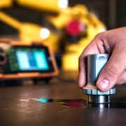
Heat Treatments for Steel Pipe

Heat Treatments for Steel Pipes: A Comprehensive Industry Knowledge

Introduction

Heat Treatments for Steel Pipes are a critical process in steel pipe manufacturing, influencing the mechanical properties, performance, and application suitability of the material. Whether improving strength, toughness, or ductility, heat treatment methods such as normalizing, annealing, tempering, and quenching ensure steel pipes can meet the demanding requirements of various industries, including oil and gas, construction, and chemical processing.

In this comprehensive blog, we will cover the most common heat treatment methods used for steel pipes. This guide will help you understand each process, its purpose, and its application, offering valuable solutions to challenges users might face in selecting the right steel pipes for their specific needs.

Key Heat Treatments for Steel Pipes

1. +N (Normalizing)

Normalizing involves heating steel to a temperature above its critical point and then allowing it to cool in air. This heat treatment refines the grain structure, enhancing the pipe’s mechanical properties, making it more uniform, and increasing strength and toughness.

  • Purpose: Improves ductility, toughness, and grain refinement.
  • Applications: Ideal for structural components subjected to impact, such as crane booms and bridges.
  • Example of Steel Grades: ASTM A106 Gr. B/C, API 5L Gr. X42–X70.

2. +T (Tempering)

Tempering is performed after quenching to reduce brittleness while maintaining hardness and strength. The process involves reheating the steel to a lower temperature, usually below its critical temperature, and then cooling it in the air.

  • Purpose: Balances hardness with increased ductility and toughness.
  • Applications: Commonly used in high-stress applications, such as shafts, gears, and heavy machinery components.
  • Examples of Steel Grades: ASTM A333, ASTM A335 (for alloy steels).

3. +QT (Quenching and Tempering)

Quenching and Tempering (QT) involves heating the steel pipe to an elevated temperature, followed by rapid cooling in water or oil (quenching) and then reheating at a lower temperature (tempering). This treatment produces pipes with excellent strength and toughness.

  • Purpose: Maximizes hardness and strength while improving toughness.
  • Applications: Ideal for high-pressure pipelines, structural applications, and oilfield components.
  • Example of Steel Grades: API 5L Gr. X65, ASTM A517.

4. +AT (Solution Annealing)

Solution Annealing involves heating stainless steel pipes to a temperature where carbides dissolve in the austenite phase and then rapidly cooling to prevent the formation of chromium carbides. This heat treatment enhances corrosion resistance.

  • Purpose: Maximizes corrosion resistance, particularly in stainless steel pipes.
  • Applications: Used for piping in the chemical, food, and pharmaceutical industries, where corrosion resistance is critical.
  • Example of Steel Grades: ASTM A312 (stainless steel).

5. +A (Annealing)

Annealing is a process that involves heating the steel to a specific temperature and then cooling it slowly in a furnace. This softens the steel, reduces hardness, and improves ductility and workability.

  • Purpose: Softens the steel for enhanced machinability and improved formability.
  • Applications: Suitable for steel pipes used in environments where forming, cutting, and machining are required.
  • Examples of Steel Grades: ASTM A179, ASTM A213 (for heat exchangers).

6. +NT (Normalizing and Tempering)

Normalizing and Tempering (NT) combines the processes of normalizing and tempering to refine the grain structure and improve the toughness of the steel pipe while enhancing its overall mechanical properties.

  • Purpose: Refines the grain structure, providing a balance between strength, toughness, and ductility.
  • Applications: Common in the manufacturing of seamless pipes for the automotive and power generation industries.
  • Examples of Steel Grades: ASTM A333, EN 10216.

7. +PH (Precipitation Hardening)

Precipitation Hardening involves heating the steel to promote the formation of fine precipitates, which strengthen the steel without reducing ductility. This is commonly used in special alloys.

  • Purpose: Increases strength through hardening without affecting ductility.
  • Applications: Used in aerospace, nuclear, and marine applications where high strength and corrosion resistance are crucial.
  • Example of Steel Grades: ASTM A564 (for PH stainless steels).

8. +SR (Cold Drawn + Stress Relieved)

Stress Relief Annealing after cold drawing is used to remove internal stresses induced during forming operations. This method improves dimensional stability and mechanical properties.

  • Purpose: Reduces residual stresses while retaining high strength.
  • Applications: Common in high-precision components such as hydraulic tubes and boiler pipes.
  • Example of Steel Grades: EN 10305-4 (for hydraulic and pneumatic systems).

9. +AR (As Rolled)

As Rolled (AR) refers to steel that has been rolled at high temperatures (above its recrystallization temperature) and allowed to cool without further heat treatment. As-rolled steel tends to have lower toughness and ductility compared to normalized or tempered steel.

  • Purpose: Provides a cost-effective option with adequate strength for less demanding applications.
  • Applications: Used in structural applications where ductility and toughness are not critical.
  • Examples of Steel Grades: ASTM A36, EN 10025.

10. +LC (Cold Drawn + Soft)

Cold drawing involves pulling the steel through a die to reduce its diameter, while Cold Drawn + Soft (LC) involves additional processing to soften the steel, improving its formability.

  • Purpose: Increases dimensional accuracy while retaining malleability.
  • Applications: Used in applications requiring high precision and formability, such as tubing for medical devices and instrumentation.
  • Example of Steel Grades: ASTM A179 (for heat exchangers and condensers).

11. +M/TMCP (Thermomechanical Controlled Process)

Thermomechanical Controlled Processing (TMCP) is a combination of controlled rolling and cooling processes. TMCP steel offers higher strength, toughness, and weldability while minimizing alloying elements.

  • Purpose: Achieves fine grain structures and improved toughness with reduced alloy content.
  • Applications: Widely used in shipbuilding, bridges, and offshore structures.
  • Example of Steel Grades: API 5L X65M, EN 10149.

12. +C (Cold Drawn + Hard)

Cold Drawn + Hard (C) refers to a steel pipe that has been cold drawn to increase strength and hardness without additional heat treatment.

  • Purpose: Provides high strength and improved dimensional accuracy.
  • Applications: Common in high-precision components where strength and accuracy are key, such as shafts and fittings.
  • Example of Steel Grades: EN 10305-1 (for precision steel tubes).

13. +CR (Cold Rolled)

Cold Rolled (CR) steel is processed at room temperature, resulting in a product that is stronger and has a better surface finish than hot-rolled steel.

  • Purpose: Produces a stronger, more accurate, and better-finished product.
  • Applications: Common in automotive components, appliances, and construction.
  • Example of Steel Grades: EN 10130 (for cold-rolled steel).

Conclusion: Choosing the Right Heat Treatment for Steel Pipes

Selecting the appropriate heat treatment for steel pipes depends on the application, mechanical properties, and environmental factors. Heat treatments such as normalizing, tempering, and quenching all serve distinct purposes in improving toughness, strength, or ductility, and selecting the right method can make a difference in performance and longevity.

By understanding the key heat treatments outlined above, you can make informed decisions that meet specific project needs, ensuring safety, efficiency, and durability in your application. Whether you’re sourcing pipes for high-pressure environments, chemical processing, or structural integrity, the right heat treatment will ensure you achieve the desired mechanical and performance characteristics.

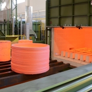
Thermal Expansion Large-Diameter Seamless Steel Pipes

How to Produce Large-Diameter Seamless Steel Pipes?

Why are Large-Diameter Seamless Steel Pipes Needed?

Large-diameter seamless steel pipes are essential for industries requiring high-strength, durable, and reliable materials that can withstand extreme pressures and harsh environments. Their seamless construction eliminates weak points, making them ideal for high-pressure applications such as oil and gas transportation, power generation, and petrochemicals. These pipes offer superior corrosion resistance, particularly in offshore, chemical, and extreme temperature conditions, ensuring longevity and minimal maintenance. Their smooth interior enhances fluid and gas flow efficiency, reducing energy loss in long-distance pipelines. Versatile in size, thickness, and material, large-diameter seamless pipes meet stringent industry standards, ensuring safety and compliance in critical infrastructure projects.

Where are Large-Diameter Seamless Steel Pipes Used?

Large-diameter seamless steel pipes are widely used in industries that demand high performance and durability under extreme conditions. They are primarily utilized in the oil and gas sector for long-distance pipeline transportation of crude oil, natural gas, and refined products due to their ability to handle high pressures and harsh environments. These pipes are also used in power generation plants, including nuclear and thermal facilities, for high-temperature and high-pressure steam lines. Additionally, they play a critical role in petrochemical processing, water supply and desalination systems, and heavy-duty construction projects, such as bridges and large-scale industrial structures, where strength and reliability are essential.

Introduction

Producing large-diameter seamless steel pipes is a specialized process that involves various manufacturing techniques, including conventional methods such as piercing and elongation, as well as more advanced approaches like the Medium Frequency Induction Heating + Hydraulic Two-Step Push-Type Thermal Expansion Method. Below is a step-by-step guide to the entire process, integrating this advanced method of thermal expansion.

Manufacturing Process of Producing Large-Diameter Seamless Steel Pipes

1. Raw Material Selection: Steel Billets

The process begins with high-quality steel billets, typically made from carbon steel, low-alloy steel, or stainless steel. These billets are carefully selected based on the application requirements for mechanical properties and chemical composition. Large-diameter seamless pipes are often used in high-pressure or corrosive environments, so the material must meet stringent standards.
Materials: API 5L, ASTM A106, ASTM A335, and other grades based on specific requirements.

2. Billet Heating (Reheating Furnace)

The steel billet is heated to around 1200–1300°C (2200–2400°F) in a reheating furnace. This process softens the billet, making it suitable for piercing and deformation. Uniform heating is essential to avoid defects in the final pipe.
Purpose: Prepare the billet for shaping by heating it to an appropriate temperature.

3. Piercing (Cross-Roll Piercing Mill)

The heated billet is then passed through a piercing mill, where it undergoes the Mannesmann process. In this stage, the solid billet is converted into a hollow shell (also called a “mother pipe”) through the action of a mandrel and rotating rollers.
Result: The billet becomes a thick-walled, hollow shell with initial irregular dimensions.

4. Elongation (Mandrel Mill or Plug Mill)

In the elongation process, the hollow shell is passed through a mandrel mill or plug mill to reduce wall thickness and increase the pipe length. This process gives the pipe its initial shape, but it still needs further dimension control.
Purpose: Achieve the desired wall thickness and length.

5. Sizing and Stretch-Reducing Mill

Next, the pipe goes through a sizing mill or stretch-reducing mill to refine its diameter and wall thickness. This step ensures that the dimensions meet the required specifications for the final product.
Purpose: Fine-tune the outer diameter and wall thickness.

6. Medium Frequency Induction Heating + Hydraulic Two-Step Push-Type Thermal Expansion Method

To produce large-diameter seamless steel pipes beyond the capabilities of conventional sizing methods, the Medium Frequency Induction Heating + Hydraulic Two-Step Push-Type Thermal Expansion Method is applied. This innovative process expands the diameter of the pipe to meet the requirements for large-diameter applications while maintaining uniformity and material integrity.

Main Steps in this Method:

Medium Frequency Induction Heating: The pipe is heated using medium-frequency induction heating, which allows precise control of the temperature along the length of the pipe. This localized heating softens the metal and prepares it for expansion, ensuring minimal thermal stress and deformation during the next step.
Hydraulic Two-Step Push-Type Expansion: After heating, the pipe is subjected to a hydraulic push-type expansion process. This process is carried out in two stages:
First Step: The pipe is pushed forward using a hydraulic system, which expands its diameter by stretching the material. This initial expansion ensures a controlled increase in size without inducing cracks or weaknesses.
Second Step: A subsequent hydraulic push further expands the pipe to the desired diameter while maintaining uniform wall thickness. This second expansion ensures that the pipe maintains structural integrity and meets dimensional tolerances.
Advantages:
Flexible and cost-effective for producing large-diameter pipes.
Maintains consistent wall thickness and mechanical properties.
Reduces the likelihood of defects such as cracks or warping during expansion.
Capable of producing larger diameters (up to 1200 mm or more) than conventional methods.
Applications: This method is widely used for large-diameter seamless pipes required in industries such as oil and gas, chemical processing, and power generation, where large sizes and excellent performance are critical.

7. Heat Treatment

Following expansion, the pipe undergoes heat treatment, depending on the required mechanical properties. Common treatments include:
Normalizing: Refines grain structure and improves toughness.
Quenching and Tempering: Enhances strength and ductility.
Annealing: Softens the pipe and enhances machinability.
The heat treatment also relieves internal stresses induced during the manufacturing process.

8. Straightening

The pipe is straightened to ensure that it conforms to the required geometric tolerances, correcting any bending or warping that occurs during the heating and expansion processes.

9. Non-Destructive Testing (NDT)

Pipes are subjected to non-destructive testing (NDT) to verify their structural integrity. This may include:
Ultrasonic Testing (UT): Detects internal defects.
Magnetic Particle Inspection (MPI): Identifies surface flaws.
Hydrostatic Testing: Ensures the pipe can withstand operational pressures.

10. Cutting and Finishing

The pipe is cut to the required length and prepared for further processing or shipment. Additional finishing operations may include:
Beveling: Pipe ends are beveled for easier welding.
Coating and Lining: Corrosion-resistant coatings or internal linings are applied.

11. Final Inspection and Packaging

The finished pipes are inspected one last time for dimensional accuracy and visual defects. They are then marked with the required specifications and prepared for shipment.

Conclusion: Flexibility in Large-Diameter Seamless Steel Pipes Production

The Medium Frequency Induction Heating + Hydraulic Two-Step Push-Type Thermal Expansion Method offers an innovative and flexible solution for producing large-diameter seamless steel pipes. By integrating this method with traditional manufacturing techniques like piercing, elongation, and heat treatment, manufacturers can produce high-quality, large-diameter pipes suitable for demanding applications such as oil and gas pipelines, structural components, and power generation systems.

This approach ensures that the pipes meet the stringent requirements for strength, corrosion resistance, and dimensional accuracy, making it a preferred choice for critical industries.

If you’re looking for more information or need assistance in selecting the right large-diameter seamless steel pipes for your project, feel free to reach out to us for expert guidance.

Piping Materials Compatibility Table

Guideline: Piping Materials Compatibility Table

Introduction

Selecting the right piping materials is critical for the safety, efficiency, and longevity of systems used in industries like oil & gas, chemical processing, and mining. Each of these industries operates in harsh environments, where piping must resist high pressures, extreme temperatures, and corrosive substances. Choosing incompatible materials could fail, leading to costly downtime, environmental hazards, and safety risks. This guide delves into the Piping Materials Compatibility Table, the most widely used piping materials, and their compatibility with fittings, flanges, valves, and fasteners, ensuring seamless operation across various industrial fields.

1. Overview of Key Materials in Piping Systems

Each industrial application comes with unique challenges, demanding materials with specific properties to withstand these conditions. Below is a breakdown of key piping materials and their characteristics:
Carbon Steel (ASTM A106): Commonly used in oil & gas for moderate temperature and pressure applications. Carbon steel is strong, durable, and cost-effective, making it suitable for general piping systems. However, it is prone to corrosion without proper protection or coatings.
Carbon Steel Alloy (ASTM A335): Designed for high-temperature service, carbon steel alloys like P11, P22, and P5 contain chromium and molybdenum, enhancing their strength and corrosion resistance at elevated temperatures.
Low-Temperature Carbon Steel (ASTM A333): Suitable for cryogenic applications, this alloy can maintain ductility at extremely low temperatures, making it ideal for LNG systems, natural gas transportation, and refrigerated chemical storage.
Stainless Steel (ASTM A312): Stainless steel grades like 304, 316, and 347 offer excellent corrosion resistance, high strength, and good formability. They are commonly used in chemical processing, where resistance to various chemicals is crucial.
API 5L (X42-X70): API 5L grades like X42, X52, and X70 are widely used in the oil and gas industry, particularly for pipelines transporting oil, gas, and water under high pressure. These grades are known for their strength, toughness, and weldability.
Duplex & Super Duplex Stainless Steel (ASTM A790): Duplex (UNS S31803, S32205) and super duplex (UNS S32750, S32760) stainless steels are known for their superior corrosion resistance, particularly in chloride-rich environments like offshore platforms. These materials provide high strength and excellent resistance to pitting and stress corrosion cracking.

2. Compatibility with Fittings, Flanges, Valves, and Fasteners

Compatibility between pipes and other components like fittings, flanges, valves, and bolts is essential for ensuring a safe, leak-free, and durable connection. Below, we explore how different materials match up across these components.

2.1 Carbon Steel Piping Systems

Pipes: ASTM A106 (Gr A/B/C) is the standard for high-temperature carbon steel piping.
Fittings: Carbon steel pipe fittings typically conform to ASTM A234 Gr WPB for welded configurations.
Flanges: ASTM A105 is the go-to for forged carbon steel flanges.
Valves: ASTM A216 Gr WCB valves are compatible with carbon steel pipes, offering durability and high-pressure performance.
Fasteners: ASTM A193 Gr B7 and A194 Gr 2H bolts and nuts are typically used for securing the flanges and other connections in carbon steel systems.

2.2 Alloy Steel Piping Systems (High-Temperature Service)

Pipes: ASTM A335 (Gr P1, P11, P22) is a staple for high-temperature piping in refineries and power plants.
Fittings: Alloy steel fittings made to ASTM A234 WP series offer good weldability and match with P-series pipes.
Flanges: ASTM A182 Gr F11 or F22 are common for flange material, depending on the pipe grade.
Valves: For high-temperature alloys, ASTM A217 Gr WC6 or WC9 valves provide reliable performance.
Fasteners: ASTM A193 Gr B7 with A194 Gr 2H nuts is a typical combination for alloy steel applications.

2.3 Low-Temperature Alloy Steel

Pipes: ASTM A333 (Gr 6 and 3) for applications down to -45°C, often used in cryogenic environments.
Fittings: ASTM A420 Gr WPL6 and WPL3 are low-temperature fittings compatible with A333 pipes.
Flanges: ASTM A350 Gr LF2/LF3 flanges are used in conjunction with low-temp piping.
Valves: ASTM A352 Gr LCB or LC3 valves are designed for low-temperature service.
Fasteners: ASTM A320 Gr L7 bolts and A194 Gr 7 nuts ensure durable connections at low temperatures.

2.4 Stainless Steel Piping Systems

Pipes: Austenitic stainless steel, like ASTM A312 Gr TP304, and TP316, is ideal for corrosion-resistant systems.
Fittings: ASTM A403 fittings (WP304/WP316) are widely used with stainless steel piping for chemical and marine applications.
Flanges: ASTM A182 Gr F304/F316 flanges complement the pipe materials.
Valves: A182 Gr F304/F316 valves are highly resistant to corrosive media, making them suitable for chemical plants and offshore environments.
Fasteners: ASTM A193 Gr B8/B8M bolts with A194 Gr 8/8M nuts are appropriate for stainless steel assemblies, ensuring corrosion resistance.

2.5 API 5L Grades for Oil & Gas Pipelines

Pipes: API 5L X42, X52, X65, and X70 grades provide high strength, flexibility, and toughness for oil and gas pipelines, especially in onshore and offshore applications.
Fittings: High-yield fittings, such as ASTM A860 Gr WPHY (42-70), match the strength of API 5L pipes.
Flanges: ASTM A694 Gr F42 to F70 flanges are suitable for high-pressure pipelines.
Valves: API 6D valves and ASTM A216 Gr WCB/WC6 are standard in these high-pressure environments.
Fasteners: Bolts conforming to ASTM A193 Gr B7 and nuts conforming to ASTM A194 Gr 2H ensure secure, high-pressure connections.

2.6 Duplex and Super Duplex Stainless Steel Systems

Pipes: Duplex stainless steel (UNS S31803/S32205) and super duplex (UNS S32750/S32760) pipes are highly resistant to both general and localized corrosion in chloride environments, making them ideal for offshore oil production and desalination plants.
Fittings: ASTM A815 Gr WP31803 and WP32750 fittings offer matching corrosion resistance and mechanical strength.
Flanges: ASTM A182 Gr F51/F53 flanges are standard for duplex systems.
Valves: Duplex valves, such as ASTM A182 Gr F51/F55, provide superior pitting resistance.
Fasteners: High-strength ASTM A193 Gr B7/B8M bolts and ASTM A194 Gr 7/8M nuts are commonly used.

Piping Materials Compatibility Table

Material Pipes Fittings Flanges Valves Bolts & Nuts
Carbon Steel A106 Gr.A
A106 Gr.B
A106 Gr.C
A234 WPA
A234 WPB
A234 WPC
A105 A216 WCB A193 Gr.B7
A194 Gr.2H
Carbon Steel Alloy High-Temp A335 P1
A335 P11
A335 P12
A335 P22
A335 P5
A335 P9
A335 P91
A225 P92
A234 WP1
A234 WP11
A234 WP12
A234 WP22
A234 WP5
A234 WP9
A234 WP91
A234 WP92
A182 F1
A182 F11
A182 F12
A182 F22
A182 F5
A182 F9
A182 F91
A182 F92
A217 WC1
A217 WC11
A217 WC12
A217 WC22
A217 WC5
A217 WC9
A217 WC91
A217 WC92
A193 Gr.B7
A194 Gr.2H
Carbon Steel Low-Temp A333 Gr.6
A333 Gr.3
A333 Gr.1
A420 WPL6
A420 WPL3
A420 WPL1
A350 LF6
A350 LF3
A350 LF1
A352 LC6
A352 LC3
A352 LC1
A320 Gr.L7
A194 Gr.7
Austenitic Stainless Steel A312 TP304
A312 TP316
A312 TP321
A312 TP347
A403 WP304
A403 WP316
A403 WP321
A403 WP347
A182 F304
A182 F316
A182 F321
A182 F347
A182 F304
A182 F316
A182 F321
A182 F347
A193 Gr.B8
A194 Gr.8
API 5L Line Pipe API 5L X42
API 5L X46
API 5L X52
API 5L X56
API 5L X60
API 5L X65
API 5L X70
A860 WPHY 42
A860 WPHY 46
A860 WPHY 52
A860 WPHY 56
A860 WPHY 60
A860 WPHY 65
A860 WPHY 70
A694 F42
A694 F46
A694 F52
A694 F56
A694 F60
A694 F65
A694 F70
API 6D
A216 WCB
A193 Gr.B7
A194 Gr.2H
Duplex Stainless Steel A790 UNS S31803
A790 UNS S32205
A815 WP31803
A815 WP32205
A182 F51
A182 F60
A182 F51
A182 F60
A193 Gr.B7
A194 Gr.7
Super Duplex Stainless Steel A790 UNS S32750
A790 UNS S32760
A815 WPS32750
A815 WPS32760
A182 F53
A182 F55
A182 F53
A182 F55
A193 Gr.B8M
A194 Gr.8M

3. Key Considerations for Material Selection

Temperature: High-temperature applications demand materials that can maintain mechanical properties at elevated temperatures, like ASTM A335 for steel alloys or A790 duplex stainless steels.
Corrosive Environment: Offshore and chemical processing applications involve exposure to highly corrosive substances like chlorides, acids, and alkalis. Stainless steel, duplex, and super duplex alloys provide excellent resistance to these environments.
Pressure: High-pressure environments, such as pipelines in oil and gas, require materials like API 5L grades paired with high-yield fittings, valves, and fasteners.
Low-Temperature Resilience: Cryogenic or refrigerated systems, such as those handling LNG, necessitate materials like ASTM A333 that retain their toughness at low temperatures.

4. Conclusion

In the oil & gas, chemical processing, and mining industries, proper material selection for piping systems is a critical aspect of system reliability and safety. Understanding the compatibility between pipes, fittings, flanges, valves, and fasteners ensures the durability and performance of the entire system. By using materials like API 5L, ASTM A106, A335, A312, and duplex stainless steels, you can match the right components to your specific operational requirements, ensuring longevity and minimizing downtime due to corrosion or mechanical failure.

When selecting materials, always consult with material experts and engineers to evaluate the precise needs of your application, taking into consideration pressure, temperature, corrosive exposure, and mechanical stresses.

Hollow Structural Section

Hollow Structural Sections (HSS): A Comprehensive Guide

Introduction

Hollow Structural Sections (HSS) have emerged as essential components in various engineering and construction applications. Their unique design, which includes square, rectangular, and circular profiles, makes them suitable for a wide range of structural uses. This blog will delve into the characteristics of HSS, and their applications in infrastructure, marine engineering, and green energy, while also discussing relevant material standards like ASTM A500, ASTM A1085, EN 10219-1, and EN 10210-1.

What Are Hollow Structural Sections?

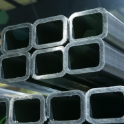
HSS are steel shapes characterized by hollow profiles, providing both strength and versatility. They are widely utilized in various construction and engineering fields due to their numerous advantages, including resistance to torsion, uniformity in strength, and aesthetic appeal.

Types of HSS

Square Sections: Offer equal dimensions on all sides, providing uniform structural strength.
Rectangular Sections: Provide versatility in design, accommodating various load requirements.
Circular Sections: Ideal for applications requiring rounded shapes, such as columns.

Advantages of HSS

High Strength-to-Weight Ratio
HSS structures can support significant loads while being lightweight, facilitating easier transportation and installation.
Uniform Strength
The hollow design provides consistent strength in all directions, making HSS suitable for dynamic loading scenarios.
Aesthetic Flexibility
HSS can be easily integrated into architectural designs, providing a modern look while serving structural purposes.
Corrosion Resistance
HSS can be treated to enhance resistance to environmental factors, making them ideal for outdoor and marine applications.

Applications of HSS

1. Infrastructure

In infrastructure projects, HSS is commonly used for:
Building Frames: Offering structural support for various types of buildings, from residential to commercial.
Bridges: Providing strength and minimizing weight, which is critical for structural integrity.

2. Marine Engineering

In marine environments, HSS proves beneficial due to:
Durability: Withstanding harsh conditions like saltwater exposure.
Piling and Foundations: Used extensively in the construction of docks, piers, and offshore platforms.

3. Green Energy

In the green energy sector, particularly in wind turbine applications, HSS is vital for:
Wind Turbine Towers: Supporting the weight of turbines while ensuring stability in high winds.
Foundations: Offering a robust base for turbines, essential for long-term reliability.

Relevant Material Standards

Understanding the standards associated with HSS is crucial for ensuring compliance and safety. Here are key standards and their relevant grades:

ASTM A500

Description: This standard covers cold-formed welded and seamless carbon steel structural tubing in round, square, and rectangular shapes.
Grades: Includes Grade A (minimum yield strength of 35 ksi), Grade B (minimum yield strength of 46 ksi), and Grade C (minimum yield strength of 50 ksi).

ASTM A1085

Description: This standard specifies cold-formed welded and seamless carbon steel structural tubing requirements, designed for improved performance.
Grades: It requires a minimum yield strength of 50 ksi and a minimum tensile strength of 65 ksi, suitable for demanding structural applications.

EN 10219-1

Description: This European standard covers the technical delivery conditions for cold-formed welded and non-welded structural hollow sections.
Grades: Various grades are defined based on yield strength, including S235JRH, S275J0H/J2H, and S355J0H/J2H, each offering different mechanical properties.

EN 10210-1

Description: This standard specifies the requirements for hot-finished structural hollow sections.
Grades: Similar to EN 10219, it includes grades such as S235JRH, S275J0H/J2H, and S355J0H/J2H, emphasizing the importance of yield strength in structural integrity.

Conclusion

Hollow Structural Sections are integral to modern construction and engineering, providing strength, versatility, and aesthetic appeal. Their applications span across infrastructure, marine engineering, and green energy, making them essential for sustainable and resilient design.

Understanding the relevant material standards, such as ASTM A500, ASTM A1085, EN 10219-1, and EN 10210-1, ensures that engineers and architects can select the appropriate HSS for their projects, meeting safety and performance requirements.

As you explore the possibilities of HSS in your next project, consider consulting with structural engineers to ensure optimal design and compliance with industry standards. This will not only enhance the integrity of your structures but also support sustainable development in various fields.

Pipe vs Tube

Pipe vs Tube: An In-depth Analysis of their Differences

Introduction

In various industries—especially oil and gas, petrochemicals, boilers, heat exchangers, mechanical, and industrial fields—pipes and tubes are crucial components. They may seem similar at first glance, but the differences between them are important when considering applications, design, and standards. Pipe vs Tube, understanding these distinctions ensures that you make the right choice for your specific needs, reducing maintenance costs, preventing failures, and optimizing performance. This guide explores the fundamental differences between pipes and tubes, providing insights into their key attributes, applications, and standards.

Understanding Pipes and Tubes: A Brief Overview

At the core, pipes and tubes are cylindrical hollow structures used to transport fluids (gases or liquids) or serve as structural members. The terms “pipe” and “tube” are often used interchangeably, but they have distinct meanings, driven by their design, manufacturing standards, and intended usage.
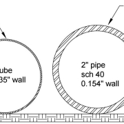
Pipes are primarily designed for transporting fluids, and their sizing focuses on internal diameter (ID), which dictates the flow rate. Tubes, on the other hand, are used where precision in dimensions is crucial—both inside and outside diameters (ID and OD) are specified for structural or critical applications.

Key Differences of Pipe vs Tube

Dimensional Tolerances
Pipes: Focus on the internal diameter (ID). The internal size is more critical as it impacts flow capacity. Wall thickness (denoted as schedule) varies based on pressure requirements.
Tubes: Emphasize both OD and ID. The wall thickness is tightly controlled, with specific dimensional tolerances. Tubes require higher precision, making them ideal for applications where strength, precision, and performance are paramount.
Measurement Systems
Pipes: Typically measured by the nominal pipe size (NPS) in North America and diameter nominal (DN) elsewhere, followed by the wall thickness (schedule). Common schedules are SCH 10, SCH 40, and SCH 80, with thicker schedules for higher-pressure applications.
Tubes: Measured by the outside diameter (OD) and wall thickness. Tube dimensions are more precise, and tolerances are tighter compared to pipes.
Manufacturing Standards
Pipes: Adhere to standards such as ASME B36.10M (for carbon steel pipes), ASME B36.19M (for stainless steel pipes), ASTM A53/A106 (for carbon steel pipes), and API 5L (for line pipes). These standards focus on dimensional flexibility to accommodate various fluid transport needs.
Tubes: Governed by stricter standards such as ASTM A213 (for seamless ferritic and austenitic steel boiler tubes), ASTM A269 (for seamless and welded austenitic stainless steel tubes), and ASTM A519 (for carbon and alloy steel mechanical tubing). These standards highlight tighter tolerances, mechanical properties, and strength.
Shape and Construction
Pipes: Almost always cylindrical and available in a wide range of diameters. The design can handle both high and low-pressure fluid flow.
Tubes: Available in a variety of shapes (round, square, rectangular, oval), offering greater versatility for structural and precision applications, including heat exchangers, mechanical systems, and architectural purposes.
Strength and Tolerance
Pipes: Typically possess lower strength-to-weight ratios. Their main focus is to withstand internal pressures, making the uniformity of the internal diameter a priority.
Tubes: Higher strength-to-weight ratios are critical, as tubes are often used in applications like hydraulic cylinders or precision instruments, where higher strength, rigidity, and consistency in dimension are vital.
End Finishes and Connections
Pipes: Available in multiple end types, including plain ends, beveled ends, and threaded ends, for easy joining using flanges, couplings, or welding.
Tubes: Typically come with smooth, plain, or threaded ends and often require specialized connections due to their precision.

Applications of Pipe vs Tube in Key Industries

Oil and Gas Industry
Pipes: In this sector, pipes are vital for transporting crude oil, natural gas, and refined products across long distances. Pipes like API 5L are designed for high-pressure environments, making them ideal for deepwater exploration, pipelines, and refineries.
Tubes: Tubes are often used in smaller-scale operations like hydraulic systems and instrumentation tubing, requiring high precision and reliability.
Petrochemicals
Pipes: Petrochemical plants rely heavily on pipes for chemical transfer and steam flow. Corrosion-resistant pipes like Alloy 825 and Hastelloy C276 are frequently used to handle aggressive chemical media.
Tubes: Heat exchangers in petrochemical plants require precision tubes to ensure efficient thermal transfer. Stainless steel tubes (ASTM A213) are widely used in heat exchangers and condensers for these purposes.
Boiler and Heat Exchanger Systems
Pipes: High-pressure steam transport relies on pipes, particularly carbon steel and alloy steel pipes like ASTM A335 (P11, P22). These pipes are designed to handle high temperatures and pressure in boilers.
Tubes: Tubes are essential in heat exchangers and condensers for transferring heat. Copper-nickel and stainless steel tubes are commonly used in these critical applications, where efficiency and reliability are paramount.
Mechanical and Industrial Fields
Pipes: Commonly used for fluid transport in mechanical systems. Steel pipes (ASTM A53, A106) are used in fire protection, plumbing, and process piping applications.
Tubes: Tubes are often used for precision structural components, hydraulic cylinders, and instrumentation. ASTM A519 and EN 10305 precision tubes are used in applications demanding high mechanical performance.

Choosing Between Pipes and Tubes: Key Considerations

Fluid Flow vs. Structural Needs
If your application involves moving fluids (gases or liquids), pipes are often the better choice because the internal diameter determines the flow rate.
If dimensional accuracy, mechanical strength, or structural integrity is essential, tubes are more suitable due to their tighter tolerances and higher strength-to-weight ratios.
Pressure and Temperature Conditions
In high-pressure and high-temperature environments, such as boilers or oil pipelines, pipes with thicker walls (high schedule) are preferred.
For heat exchangers or hydraulic systems, where precision and efficient thermal or hydraulic transfer are critical, tubes offer better performance.
Corrosion Resistance
In highly corrosive environments, stainless steel or alloy pipes and tubes (e.g., Alloy 625, 825, or Hastelloy) should be selected based on specific resistance requirements. Tubes may be used for specific equipment or systems requiring superior mechanical properties and corrosion resistance.
Cost Considerations
Pipes are generally less expensive than tubes due to their lower manufacturing precision requirements. For large-scale fluid transport, pipes are a cost-effective solution.

Tubes, due to their precision and strength, are more expensive but provide long-term value in precision applications, such as instrumentation or high-performance heat exchangers.

Conclusion: Pipe vs Tube, Making the Right Choice

Understanding the differences between pipes and tubes is crucial for ensuring the best performance in industrial applications. Pipes, with their focus on fluid flow and internal diameter, are ideal for transporting fluids in oil and gas, petrochemicals, and boiler systems. Tubes, on the other hand, excel in applications requiring precision, structural integrity, and strength, such as in heat exchangers, mechanical systems, and instrumentation.

When selecting between the two, consider factors such as dimensional precision, pressure and temperature requirements, corrosion resistance, and overall application demands. By doing so, you’ll ensure that your system operates efficiently, safely, and cost-effectively in the long term.

Non-Destructive Testing (NDT)

Nondestructive Testing (NDT): A Comprehensive Guide

Introduction

In industries where material integrity and safety are paramount, Nondestructive Testing (NDT) plays a crucial role. It allows engineers and technicians to inspect and evaluate materials, components, and structures without causing any damage. This means the tested item can continue to be used after inspection, ensuring both safety and efficiency.

What is NDT?

Nondestructive Testing (NDT) refers to a range of analysis techniques used to evaluate the properties of a material, component, or system without causing damage. NDT is crucial in industries like aerospace, construction, oil and gas, and manufacturing, where the failure of materials or structures can lead to catastrophic consequences. By using NDT, companies can ensure product integrity, quality, and safety while also preventing accidents.

Why is NDT Important?

Safety Assurance: In sectors like oil and gas, aerospace, and construction, safety is paramount. NDT helps detect potential flaws before they result in failures, protecting both workers and the public.
Cost-Efficiency: Since NDT does not damage the tested object, it eliminates the need for replacement or repair of the item post-testing. This leads to reduced downtime and lower inspection costs.
Quality Control: NDT helps maintain high-quality standards by ensuring that materials and components meet industry specifications and standards.
Compliance: Many industries are governed by strict regulatory standards. NDT is often a mandatory part of compliance, ensuring that components are safe and fit for purpose.

Common NDT Methods

There are several NDT techniques, each suitable for different types of materials and flaws. Here are some of the most commonly used methods:

1. Ultrasonic Testing (UT)

How It Works: Ultrasonic waves are transmitted into a material. Flaws or changes in material properties cause reflections, which are detected and analyzed.
Applications: Used for detecting internal defects in metals, plastics, and composites. Common in pipeline inspections, weld inspection, and metal thickness measurement.
Advantages: Can detect deep-seated flaws and provide accurate measurements.

2. Radiographic Testing (RT)

How It Works: X-rays or gamma rays are passed through a material, and the resulting image is captured on film or a digital detector. Flaws appear as variations in the image.
Applications: Ideal for inspecting welds, castings, and structural components.
Advantages: Can detect internal and surface defects in thick materials.

3. Magnetic Particle Testing (MT)

How It Works: A magnetic field is applied to a ferromagnetic material. Surface and near-surface defects disturb the magnetic field, causing magnetic particles to gather and form an indication.
Applications: Used for detecting surface and subsurface defects in ferromagnetic materials like steel.
Advantages: Quick and easy to apply, making it suitable for large areas.

4. Liquid Penetrant Testing (PT)

How It Works: A liquid penetrant is applied to the surface of a material. The liquid enters any surface-breaking defects. Excess penetrant is removed, and a developer is applied to draw the penetrant out of the defects, making them visible.
Applications: Commonly used for detecting cracks and other surface-breaking defects in metals, plastics, and ceramics.
Advantages: Simple, cost-effective, and can be applied to various materials.

5. Eddy Current Testing (ECT)

How It Works: An alternating current is passed through a coil, creating an electromagnetic field. When the coil is placed near a conductive material, eddy currents are induced. Changes in these currents indicate flaws.
Applications: Used for detecting surface and near-surface defects in conductive materials, especially in aerospace and automotive industries.
Advantages: Sensitive to small cracks and can be used on coated materials.

6. Visual Testing (VT)

How It Works: The most basic form of NDT, using the naked eye or optical instruments to examine the surface of a material.
Applications: Suitable for detecting visible defects like cracks, corrosion, and misalignment in welds and structural components.
Advantages: Simple, low-cost, and can provide immediate results.

Nondestructive Testing (NDT) and Relevant Standards

Nondestructive Testing (NDT) methods are governed by various standards to ensure consistency, reliability, and safety. These standards are set by organizations like the American Society for Testing and Materials (ASTM) and the European Committee for Standardization (EN). Here’s a breakdown of the EN and ASTM standards relevant to each NDT method.

1. Ultrasonic Testing (UT)

Ultrasonic Testing (UT) uses high-frequency sound waves to detect internal flaws in materials. It’s widely used in industries like pipeline inspection, metal thickness measurement, and weld inspection.
EN Standards:
EN 12668: This standard specifies the requirements for equipment used in ultrasonic testing, including probes, ultrasonic pulser/receivers, and cables.
EN ISO 16810: Covers general principles of ultrasonic testing.
EN 10160: Pertains to ultrasonic testing of steel flat products of thickness equal to or greater than 6 mm.
ASTM Standards:
ASTM E114: A guide for ultrasonic pulse-echo straight-beam examination by the contact method.
ASTM E164: A practice for ultrasonic contact examination of welds and other materials.
ASTM E2375: A practice for ultrasonic testing of wrought products.
ASTM A388: A practice for ultrasonic examination of steel forgings.

2. Radiographic Testing (RT)

Radiographic Testing (RT) uses X-rays or gamma rays to produce an image of the material’s interior, revealing internal defects such as cracks, voids, or inclusions.
EN Standards:
EN ISO 17636-1: Specifies the techniques for radiographic testing of fusion-welded joints in metallic materials.
EN ISO 11699-1: Defines the classification of film systems for industrial radiography.
EN 444: Addresses the examination of metallic materials by radiography.
ASTM Standards:
ASTM E94: A guide for radiographic examination.
ASTM E1032: A practice for radiographic examination of weldments.
ASTM E1742: A practice for radiographic examination using industrial X-ray film.
ASTM E747: A practice for designing image quality indicators (IQI) used in radiography.

3. Magnetic Particle Testing (MT)

Magnetic Particle Testing (MT) is used for detecting surface and near-surface flaws in ferromagnetic materials. It relies on magnetic fields and magnetic particles to identify defects.
EN Standards:
EN ISO 9934-1: Covers general principles for magnetic particle testing.
EN ISO 17638: Specifies the method for magnetic particle testing of welds.
EN 1369: Pertains to magnetic particle inspection of castings.
ASTM Standards:
ASTM E709: A guide for magnetic particle testing.
ASTM E1444: A practice for magnetic particle testing.
ASTM A275: A practice for magnetic particle examination of steel forgings.

4. Liquid Penetrant Testing (PT)

Liquid Penetrant Testing (PT) is used for detecting surface-breaking defects in non-porous materials. It involves applying a liquid penetrant to the surface and using a developer to draw out the penetrant from defects, making them visible.
EN Standards:
EN ISO 3452-1: Defines general principles for liquid penetrant testing.
EN ISO 3452-2: Specifies the testing materials for penetrant testing.
EN 1371-1: Pertains to the liquid penetrant inspection of castings.
ASTM Standards:
ASTM E165: A practice for liquid penetrant examination.
ASTM E1417: A practice for liquid penetrant testing.
ASTM E433: A reference photomicrographs for liquid penetrant inspection.

5. Eddy Current Testing (ECT)

Eddy Current Testing (ECT) is used for detecting surface and near-surface defects in conductive materials. It involves inducing eddy currents in the material and analyzing the resulting electromagnetic response.
EN Standards:
EN ISO 15548-1: Specifies the equipment used for eddy current testing.
EN 1711: Addresses the eddy current examination of welds.
EN 4050-1: Relates to the eddy current inspection of aerospace structures.
ASTM Standards:
ASTM E376: A practice for measuring coating thickness by eddy current.
ASTM E215: A practice for standardizing equipment for eddy current examination.
ASTM E243: A practice for the electromagnetic examination of seamless aluminum-alloy tube.

6. Visual Testing (VT)

Visual Testing (VT) is the simplest form of NDT, involving a visual examination of materials, components, or structures, often with the aid of optical instruments.
EN Standards:
EN ISO 17637: Specifies visual testing of fusion-welded joints.
EN 13018: Covers general principles of visual testing.
EN 970: Relates to visual examination of welds.
ASTM Standards:
ASTM E165: A practice for liquid penetrant examination (also applicable to visual examination).
ASTM E1316: A terminology for Nondestructive Examinations, including visual testing.
ASTM E337: A practice for making measurements on spectral plots for visual testing.

Choosing the Right NDT Method

Selecting the appropriate NDT method depends on various factors:
Material Type: Different materials respond differently to NDT methods. For example, Magnetic Particle Testing is suitable for ferromagnetic materials, while Eddy Current Testing works well with conductive materials.
Defect Type: The nature of the defect (surface-breaking, subsurface, internal) determines the best inspection method.
Accessibility: The accessibility of the test area can influence the choice of NDT method. Some methods require access to only one side of the material, while others need access to both.
Cost and Time: Each method varies in terms of cost, time, and equipment requirements. Balancing these factors against inspection needs is crucial.

Implementing NDT in Your Operations

If you’re considering integrating NDT into your operations, here are some steps to guide you:
Assess Your Needs: Identify the types of materials and components you work with and the types of defects you need to detect.
Consult Experts: NDT specialists can help you choose the most appropriate method and provide training for your team.
Invest in Quality Equipment: Ensure you use reliable and calibrated NDT equipment to obtain accurate results.
Train Your Personnel: NDT requires skilled technicians. Invest in proper training and certification for your personnel.
Regular Inspections: Implement a regular inspection schedule to ensure ongoing safety and compliance.

Common Challenges and Solutions in NDT

False Indications: NDT can sometimes produce false positives or negatives, leading to incorrect assessments. Solution: Use multiple NDT methods to cross-verify results and ensure personnel are well-trained.
Access Limitations: Some components may be difficult to access for testing. Solution: Use portable NDT equipment and techniques suitable for hard-to-reach areas.
Environmental Conditions: Factors like temperature, moisture, and lighting can affect certain NDT methods. Solution: Prepare the inspection area adequately and choose methods that are less sensitive to environmental conditions.

Conclusion

Nondestructive Testing (NDT) is an invaluable tool for ensuring the safety, reliability, and integrity of materials and structures across various industries. By selecting the right NDT method and implementing it effectively, companies can detect potential issues early, reduce maintenance costs, and ensure compliance with industry standards. Whether you’re in aerospace, construction, or oil and gas, NDT offers a solution to maintaining high-quality standards while preventing failures and accidents.