How to Select Materials: Material Selection Guidelines
Introduction
Material selection is a critical step in ensuring the reliability, safety, and performance of equipment across industries such as oil and gas, chemical processing, marine engineering, aerospace, and many more. The right material can prevent corrosion, withstand extreme temperatures, and maintain mechanical integrity in harsh environments. Steels and alloys such as carbon steels, alloy steels, stainless steels, nickel, titanium, and various high-performance superalloys like Inconel, Monel, and Hastelloy offer specific advantages that make them ideal for these demanding applications. This blog provides a comprehensive overview of material selection guidelines, focusing on key materials and their suitability based on corrosion resistance, mechanical properties, and temperature capabilities. By understanding these properties, engineers and decision-makers can optimize material selection to ensure long-term performance and operational efficiency.
Material Selection Guidelines: Table 1 – List of Abbreviations
| Abbreviations | |
| API | American Petroleum Institute |
| ASTM | American Society for Testing and Material |
| CA | Corrosion Allowance |
| CAPEX | Capital Expenditures |
| CO2 | Carbon Dioxide |
| CMM | Corrosion Monitoring Manual |
| CRA | Corrosion-Resistant Alloy |
| CRAS | Corrosion Risk Assessment Study |
| Cr Steel | Chrome Stainless Steel |
| 22Cr | Duplex Stainless Steel type 2205 (for example UNS S31803/S32205) |
| 25Cr | Super duplex stainless steel 2507 (for example UNS S32750) |
| CS | Carbon Steel |
| CTOD | Crack Tip Opening Displacement |
| DSS | Duplex Stainless Steels |
| ENP | Electroless Nickel Plating |
| EPC | Engineering, Procurement, and Construction |
| GRP | Glass Reinforced Plastic |
| HAZ | Heat Affected Zone |
| HV | Vickers Hardness |
| HIC | Hydrogen-Induced Cracking |
| H2S | Hydrogen Sulphide |
| ISO | International Organization of Standardization |
| LTCS | Low-Temperature Carbon Steel |
| MCA | Materials and Corrosion Audit |
| MSDs | Materials Selection Diagrams |
| MSR | Material Selection Report |
| N.A. | Not Applicable |
| NACE | National Association of Corrosion Engineers |
| OPEX | Operating Expenditures |
| PFDs | Process Flow Diagrams |
| pH | Hydrogen Number |
| PMI | Positive Material Identification |
| PREN | Pitting Resistance Equivalent Number = %Cr + 3.3 (%Mo+0.5 %W) + 16 %N |
| (C-)PVC | (Chlorinated) Polyvinyl Chloride |
| PWHT | Post-Weld Heat Treatment |
| QA | Quality Assurance |
| QC | Quality Control |
| RBI | Risk-based inspection |
| SAW | Submerged arc welded |
| SDSS | Super Duplex Stainless Steel |
| SOR | Statement of Requirement |
| SOW | Scope of Work |
| SS | Stainless Steel |
| WPQR | Welding Procedure Qualification Record |
| UFDs | Utility Flow Diagrams |
Material Selection Guidelines: Table 2 – Normative References
| Ref. | Document No. | Title |
| (1) | ASTM A262 | Standard practice for detecting susceptibility to intergranular attack |
| (2) | NACE MR0175 / ISO 15156 | Petroleum, petrochemical and natural gas industries – Materials for use in H2S-containing environments in oil and gas production |
| (3) | NACE SP0407 | Format, content, and guidelines for developing a materials selection diagram |
| (4) | ISO 21457 | Petroleum, petrochemical and natural gas industries – Materials selection corrosion control for oil and gas production systems |
| (5) | NACE TM0177 | Laboratory testing of metals for resistance to sulfide stress cracking and stress corrosion |
| (6) | NACE TM0316 | Four-point bend testing of materials for oil and gas applications |
| (7) | NACE TM0284 | Standard test method – evaluation of pipeline and pressure vessel steels for resistance to hydrogen-induced cracking |
| (8) | API 6DSS | Specification for subsea pipeline valves |
| (9) | API RP 945 | Avoiding environmental cracking in Amine units |
| (10) | API RP 571 | Damage mechanisms affecting fixed equipment in the refining industry |
| (11) | ASTM A263 | Standard specification for stainless chromium steel-clad plate |
| (12) | ASTM A264 | Standard specification for stainless chromium-nickel steel-clad plate |
| (13) | ASTM A265 | Standard specification for nickel and nickel-base alloy-clad steel plate |
| (14) | ASTM A578 | Standard specification for straight-beam ultrasonic examination of rolled steel plates for special applications |
| (15) | ASTM A153 | Standard Specification for Zinc coating (hot-dip) on iron and steel hardware |
| (16) | NACE MR0103/ISO 17945 | Petroleum, petrochemical and natural gas industries – Metallic materials resistant to sulfide stress cracking in corrosive petroleum refining environments |
| (17) | ASTM A672 | Standard specification for electric-fusion-welded steel pipe for high-pressure service at moderate temperatures |
| (18) | NACE SP0742 | Methods and controls to prevent in-service environmental cracking of carbon steel weldments in corrosive petroleum refining environments |
| (19) | API 5L | Specification for Line Pipe |
| (20) | NACE SP0304 | Design, installation, and operation of thermoplastic liners for oilfield pipelines |
| (21) | DNV RP O501 | Erosive wear in piping systems |
Material Selection Guidelines: Table 5 – Parameters Used for Corrosion Evaluation
| Parameter | Units |
| Design Life | Years |
| Operating Temperature Range | °C |
| Pipe Diameter | mm |
| Design Pressure | MPa |
| Dewpoint Temperature | °C |
| Gas to Oil Ratio (GOR) | SCF / SBO |
| Gas, Oil & Water Flow Rate | tonnes/day |
| CO2 Content & partial pressure | Mole % / ppm |
| H2S Content & partial pressure | Mole % / ppm |
| Water Content | % |
| pH | N.A. |
| Chloride Content | ppm |
| Oxygen | ppm/ppb |
| Sulfur | wt% / ppm |
| Mercury | wt% / ppm |
| Acetic Acid Concentration | mg/l |
| Bicarbonate Concentration | mg/l |
| Calcium Concentration | mg/l |
| Sand/Solid Particle Content (Erosion) | kg/hour |
| Potential for Microbially Induced Corrosion (MIC) | N.A. |
It is COMPANY policy to use Carbon Steel (CS) whenever possible for the construction of production systems, processing equipment and pipelines. A Corrosion Allowance (CA), adequate for the asset to achieve the required service life is provided to accommodate corrosion (Section 11.2), and wherever feasible, corrosion inhibition (Section 11.4) is supplied to reduce the risk of pitting and reduce the rate of corrosion.
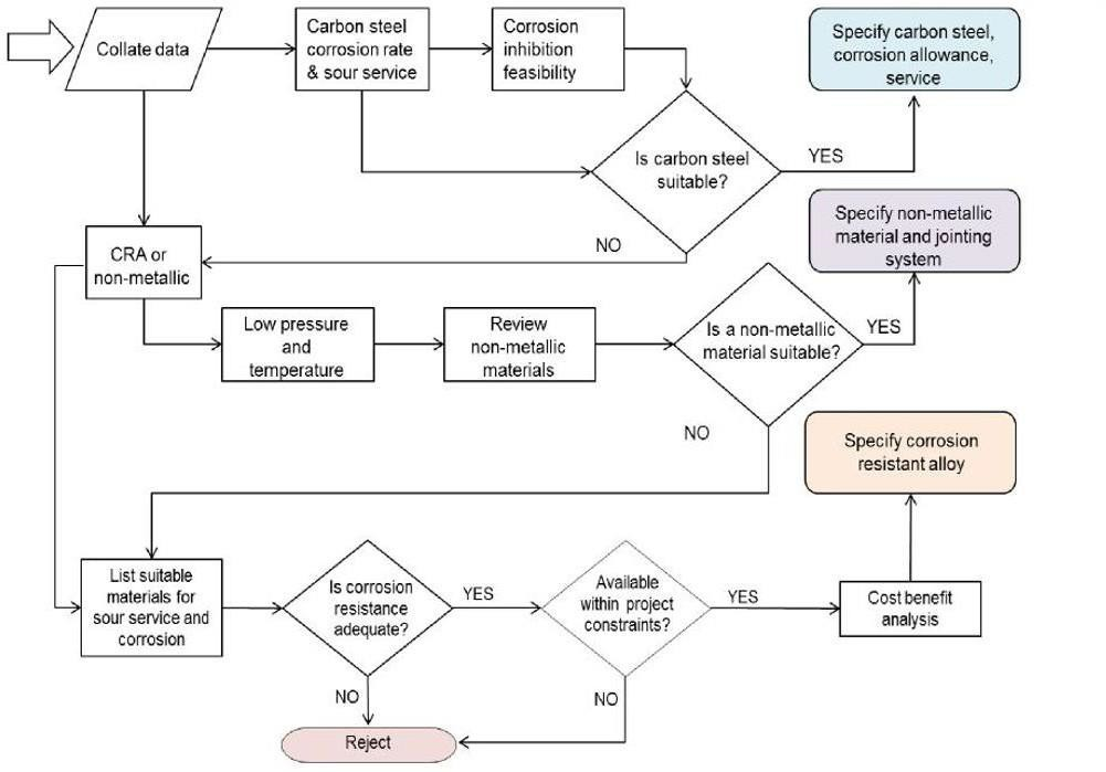
Where the use of CS is not a technical and economic option and/or where a failure by corrosion would pose an acceptable risk to personnel, the environment, or COMPANY assets, Corrosion Resistant Alloy (CRA) may be used. Alternatively, if the service life corrosion of CS with inhibitor treatment exceeds 6 mm, CRA will be selected (Solid or Clad CRA). Selection of a CRA should ensure that the optimum alloy is selected based on cost-performance criteria. A material selection flow diagram is shown in Figure 1 to outline the process by which material selection alternate to CS may be justified.
Figure 1 – Material Selection Flow Diagram
Material Selection Guidelines: Corrosion Allowance
CA, for CS, shall be specified based on anticipated corrosion rates or material degradation rates under the most severe combination of process parameters. Specifying CA should be properly engineered and justified noting that when short-term material performance or transient conditions are anticipated to increase general or localized corrosion risks, upset duration shall be estimated based on prorated corrosion rates. Based on these, extra corrosion allowances may be required. Therefore, the CRAS needs to be carried out at an early stage of the project.
The CA itself shall not be considered as an assured corrosion control measure. It shall be considered only as a measure to provide time to detect measure and assess the rate of corrosion.
Depending on the Project’s requirements and conditions, the permittable CA can be increased above 6 mm where the estimated corrosion rate exceeds 0.25 mm/y. However, this will be discussed on a case-by-case basis. When corrosion allowances are excessive, material upgrades shall be considered and evaluated. The selection of CRA should ensure that the optimum alloy is selected based on the cost-performance criterion.
The following guidelines shall be used to specify the level of CA:
- The CA is the product of multiplying the estimated corrosion rate of the selected material by the design life (including possible life extension), rounded to the nearest 3.0, 4.5 or 6.0 mm.
- Corrosion due to CO2 can be assessed using COMPANY-approved corrosion models such as ECE- 4 & 5, Predict 6.
- The corrosion rate used to estimate the CA shall be based on past plant experience and the available published data for process conditions which should include:
- Corrosivity of fluid, for example, the presence of water combined with hydrogen sulfide (sour corrosion), CO2 (sweet corrosion), oxygen, bacteriological activity, temperature and pressures;
- Velocity of fluid that determines the flow regime in the pipeline;
- Deposition of solids that may prevent adequate protection by inhibitors and create conditions for the growth of bacteria; and
- Conditions that may cause pipe wall
- CS and low alloy steel of pressure parts shall have a minimum of 3.0 mm. In special cases 1.5 mm may be specified with COMPANY approval; considering the design life of the item under consideration. Examples of mild or non-corrosive services, where 5 mm CA may be specified, are steam, deaerated boiler feed water (< 10 ppb O2), treated (non-corrosive, chloride controlled, bacteria free) fresh cooling water, dry compressed air, hydrocarbons containing no water, LPG, LNG, dry natural gas, etc. Nozzles and manhole necks shall have the same CA as specified for the pressure-containing equipment.
- Maximum CA shall be 6.0 mm. Depending on the Project’s requirements and conditions, the permittable CA can be increased above 6 mm where the estimated corrosion rate exceeds 0.25 mm/y. However, this will be discussed on a case-by-case basis. When corrosion allowances are excessive, a material upgrade shall be considered and the Selection of CRA should ensure that the optimum alloy is selected based on the cost-performance criterion.
- The layout of the installation and its effect on the flow rate (including dead legs).
- Failure probabilities, failure modes, and failure consequences for human health, environment, safety, and material assets, are all determined by carrying out a risk assessment not only for Materials but for other disciplines as well.
- Access to maintenance and
For the final materials selection, the following additional factors shall be included in the evaluation:
- Priority shall be given to materials with good market availability and documented fabrication and service performance, for example, weldability, and inspection ability;
- The number of different materials shall be minimized considering stock, costs, interchangeability, and availability of relevant spare parts;
- Strength to weight (for offshore); and
- Frequency of pigging/cleaning. No CA shall be required for:
- The backing material of items with alloy cladding or weld
- On the gasket facing of
- For CRAs. However, for CRAs in erosive service, a 1 mm CA shall be specified. This shall be addressed and supported by erosion modelling via DNV RP O501 [Ref. (e)(21)] (or similar models when approved for use by the COMPANY).
Note: When short-term or transient conditions are anticipated to increase general or localized corrosion risks, upset duration shall be estimated based on prorated corrosion rates. Based on these, higher corrosion allowances may be required. Additionally, CRA piping or CRA internally clad/lined piping shall be used for areas of high fluid velocity and expected erosion-corrosion.
Material Selection Guidelines: Metallic Cladding
To mitigate the risk of corrosion where corrosion rates are over a 6 mm CA, it may be suitable to specify a CS parent material with a layer of CRA cladding or weld overlay material. Where there is any doubt the specifier of materials shall seek advice from COMPANY. Where CRA cladding of vessels is specified or CRA cladding is applied by explosive weld bonding, metallic roll bonding, or weld overlay, SSC resistant quality base plate is required, but HIC resistant base plate is not required.
If explosion bonding or roll bonding is the selected option, a minimum thickness of 3 mm shall be achieved across 100% of the parent material. If overlay is the selected option, there should be a minimum of 2 passes and a minimum thickness of 3 mm shall be achieved. If there is a weldability issue, then explosive bonding can be considered.
Common cladding materials include:
- 316SS (type 317SS may be specified where there is a higher risk of chloride pitting);
- Alloy 904;
- Alloy 825 (limited to roll bonding as welding may result in inferior corrosion resistance in clad plate); and
- Alloy
Where the thickness of the vessel is relatively thin (up to 20 mm), a lifecycle cost analysis shall be used to decide whether a solid CRA material selection is more commercially viable. This shall be considered on a case-by-case basis.
Clad or lined pipe may be used for flowlines that transport highly corrosive fluids. The requirements of API 5LD apply. For economic reasons, these pipelines will be of modest diameter and short length. Clad pipe is formed from a steel plate that has a 3 mm layer of CRA bonded to its internal surface. The CRA clad can be either metallurgically bonded, co-extruded, or weld overlaid, or for subsea applications, process/mechanical bonding can be used when depressurizing risk is low. For welded pipe specification CRA cladded pipe is formed to the pipe and the seam is welded with CRA consumables.
The CONTRACTOR shall issue separate specifications based on existing COMPANY-specific specifications for alloy clad or weld overlay on CS, covering the requirements for the design, fabrication, and inspection of applied lining and integral cladding for pressure vessels and heat exchangers. The ASTM specifications A263, A264, A265, A578, and E164, and NACE MR0175/ISO 15156 may be used for reference.
Material Selection Guidelines: Application of Corrosion Inhibitor
Selection of corrosion inhibitor and evaluation shall be as per the Company’s Procedure. For design purposes, 95% corrosion inhibition efficiency shall be assumed for gas condensate and 90% for oil. Additionally, during design, the inhibitor availability shall be based on 90% availability, during the operational phase the minimum inhibitor availability shall be >90%. The inhibitor availability shall be specified during the FEED stage on a project-to-project basis. However, the use of corrosion inhibitors shall not act as a substitute for NACE MR0175/ISO 15156 sour service material selection requirements.
To enable the effectiveness of the inhibition system to be verifiable during operation, the following shall be included in the design:
- The locations of the highest potential corrosion
- Accessibility of high potential corrosion rate locations for wall thickness measurement during
- Ability to take samples for solids/debris
- Corrosion measurement equipment should be used to monitor the effectiveness of the inhibition
- Facilities to allow iron counts should be included in the design for monitoring inhibited
Provision shall be made in the design so that the following Key Performance Indicators (KPI) can be measured and trended for inhibited systems:
- The number of hours the inhibition system is not
- Actual injected concentration compared with target injection
- Inhibitor residual concentration compared to target
- Average corrosion rate as compared to target inhibited corrosion
- Changes in corrosion rate or dissolved iron levels as a function of
- Unavailability of corrosion monitoring
Material Selection Guidelines: Material for Sour Service
Materials selection for piping and equipment for use in H2S-containing environments shall comply with the latest COMPANY Specification for Materials in Sour Environments and be verified to NACE MR0175/ISO15156 for upstream processes and NACE MR0103/ISO 17945 for downstream processes.
316L SS shall be considered for most sour services except where higher temperatures >60 °C occur together with a high H2S and chloride content of the fluid, however, this will be considered on a case-by-case basis. For operating conditions outside of these limitations, higher alloy materials may be considered in compliance with NACE MR0175/ISO15156. Additionally, consideration should be given to vapor separation where the chloride content carryover will be reduced.
316L SS cladding may be considered for vessels when following the environmental and materials limits from Table A2 in ISO 15156, part 3. Vessels clad with 316L must be allowed to cool below 60 °C before opening as there is a risk of chloride stress cracking of the cladding when exposed to oxygen. For operating conditions outside of these limitations, higher alloy materials may be considered in compliance with NACE MR0175/ISO15156. Cladding shall be inspected to ensure that it is continuous over 100% of the complete surface including any nozzles and any other attachments.
Steel for sour service piping shall be HIC resistant have a sulfur content <0.01% and be secondary treated with calcium for inclusion shape control. Steel for longitudinally welded pipe shall have a sulfur content <0.003% and be secondary treated with calcium for inclusion shape control.
Specific guidelines for bolting in sour service environments can be found in the bolting section of this guideline; Section 12.8.
When sour service requirements are specified by the purchaser, the following shall apply:
- All materials shall be marked to ensure full traceability to melt and heat treatment
- Heat treatment For tempered conditions, tempering temperature shall be stated.
- The supplementary suffix ‘S’ shall be used to designate a material delivered in accordance with the MDS plus the additional supplementary requirements for sour service excluding HIC testing and UT examination.
- The supplementary suffix ‘SH’ shall be used to designate a material delivered in accordance with the MDS including the additional supplementary requirements for sour service plus HIC testing and UT
- The material manufacturer shall have a quality system certified in accordance with ISO 9001 or another quality requirements standard accepted by the purchaser.
- The inspection documents shall be issued in accordance with ISO 10474 /EN 10204 Type 1 and shall confirm compliance with this specification.
- Fully killed materials must be
- For sour service pipe, materials shall comply with the requirements of API 5L Annex H – PSL2. For severe sour service, low strength normalized grades are specified, limited up to X65 grades.
- Sour service testing is required on both base material and weldments and routine testing for SSC and HIC shall accord with NACE TM0177 and NACE TM0284. Testing for SOHIC and soft zone cracking may require full ring testing with the welds produced using the actual manufacturing weld Four-point bend testing shall be carried out in accordance with NACE TM0316.
- Hardness as per ISO 15156 for upstream, and NACE MR0173/NACE SP0742 for
Material Selection Guidelines: Specific Considerations
The following list contains specific material selection considerations that are not specific to any given system and shall be applied to all COMPANY Projects:
- The CONTRACTOR shall be fully responsible for the material selection made by any LICENSOR I in any packaged equipment. The CONTRACTOR shall provide for all information including MSDs, material selection philosophies, CRAS, RBI, and MCA in line with this specification for COMPANY approval. Any change of material will be warranted under the CONTRACTOR.
- Attention shall be given to the fracture toughness properties of pipe materials to prevent the possibility of brittle fracture.
- Aluminum bronze material shall not be used in welded parts because of poor weldability and maintenance problems.
- Electroless Nickel Plating (ENP) shall not be used unless approved by
- Material for the Lube and Seal Oil system shall be SS316L if its suitability is
- Rubber linings in water boxes of surface condensers and other exchangers shall not be used without COMPANY approval.
- Use of GRE/HDPE material for low-pressure oil and gas, water, oily, and stormwater, drains within acceptable service parameters and loading (when buried) limits by manufacturer is permitted with COMPANY’s approval.
- The design of any heat exchangers shall be based on their process requirements. Therefore, material selection is bespoke for all heat exchangers and cannot/should not be standardized.
- Stainless steel 304, 304L shall not be used as an external material application where it’s not suitable for the humid laden atmosphere of UAE.
FBE Coated Pipeline
Material Selection Guidelines: Specific Applications and Systems
This section gives material guidelines for specific systems that are present within the COMPANY’s range of facilities including its upstream (both onshore and offshore) and downstream (refinery) assets. An overview
of the units found within these facilities, the material options, potential damage mechanisms, and mitigation for such mechanisms are given in the following tables. Further detail for each unit is given throughout the remainder of this Section. For further details on the listed corrosion mechanisms, see API RP 571.
Note: Material options given in this section shall be taken as a guideline only. The CONTRACTOR shall be responsible for project-specific material selection throughout each phase of the Project through the deliverables specified in Section 10.
Material Selection Guidelines: Table 6 – Material Recommendations for Upstream Process Equipment and Piping
| Service | Material Options | Damage Mechanisms | Mitigation |
| Wellhead rigid spools/Jumper and Manifolds | CS+CRA Cladding, CRA, CS+CA | CO2 corrosion, Wet H2S Damage, Chloride Stress Corrosion Cracking (CSCC) | Material Selection. (When Corrosion Inhibition is deemed ineffective at such locations/highly corrosive service/CRA clad option recommended) Design for sour service. UNS N06625/UNS N08825 clad option. NACE MR0175/ISO 15156 sour service requirements apply for sour service. |
| Pipeline/Flowline | CS+CA | Hydrogen embrittlement, CO2 corrosion, Wet H2S Damage, CSCC, MIC | Cathodic protection and coating to protect buried metallic section. Use of biocide corrosion inhibitor, and pig/scrapper. Periodic Inline Inspection (Intelligent Pigging) to measure wall thickness and periodic cleaning using appropriate cleaning pig. |
| Wet Hydrocarbon Gas | CS+CA (+CA/CRA Cladding), 316SS, DSS, SDSS |
CO2 corrosion, Wet H2S Damage, CSCC, chloride pitting, | Material Selection Design for sour service TOL corrosion is to be assessed, and mitigation is to specify CRA clad when corrosion allowance exceeds 6mm. Use of corrosion inhibitor NACE MR0175 /ISO 15156 sour service requirements apply for sour service. Selection at the inlet is predominantly based on sour service requirements |
| Dry Hydrocarbon Gas | CS+CA (+CRA Cladding), 316SS | CO2 corrosion, Wet H2S Damage. | Material Selection Ensure operation is within specified conditions envelope Corrosion monitoring is vital to ensure gas remains dry. CA may be required if periods of wetness are possible. |
| Stabilized Condensate | CS+CA | CO2 corrosion, Wet H2S Damage, MIC | Material Selection Monitoring of bacterial activity |
| Produced Water | CS+CA, 316SS, DSS, SDSS. CS+CRA liner, CS+CRA (metallurgical bonded) | CO2 Corrosion, Wet H2S Damage, CSCC, MIC, O2 corrosion | Material selection Design to prevent oxygen ingress Use of biocide, O2 scavenger, and corrosion inhibitor CS + internal lining may be selected for vessels. Specification of pipe material is highly dependent on process/fluid conditions. NACE MR0175 /ISO 15156 sour service requirements apply for sour service. |
| Export Oil/Gas Export/Feed Gas | CS+CA | CO2 corrosion, Wet H2S Damage, MIC | Material Selection For Gas export Dew point temperature monitoring If gas export is considered ‘wet’, an upgrade to CRA (clad /solid) material may be required based on corrosion assessment results. |
| Gas Dehydration (TEG) | CS+CA, 316SS, CS+CRA | Corrosion from acid condensation in still column overheads | Material selection is licensor-driven; however, the responsibility lies with the CONTRACTOR. |
| Injection Chemicals (for example corrosion inhibitors) | CS(+CA), 316SS, C-PVC | Chemical compatibility, corrosion. | Materials selection shall be discussed with VENDOR/SUPPLIER in terms of chemical compatibility. |
| Mercury Removal | CS+CA | CO2 corrosion, Wet H2S Damage, CSCC, chloride pitting *Liquid metal embrittlement |
Material selection *Aluminium or copper-bearing titanium alloys shall not be used where there is a risk of liquid mercury. |
| Amine | CS+CA/CRA Cladding, 316SS | CO2 corrosion, wet H2S damage, Amine Stress Corrosion Cracking (ASCC), amine corrosion, erosion (from heat-stable salts) | Suitable operation velocities, temperatures for the designed system, and regular sampling to check for amine salts. Rich amine shall be 316SS. The vessel’s internal shall be 316SS. Velocity limits. PWHT shall be specified for CS to prevent ASCC when the design temperature is > 53°C. PWHT temperature to be used shall be as per API RP945. |
| Flare | CS+CA, 316SS *310SS, 308SS, Alloy 800, Alloy 625 |
Low-temperature fracture, atmospheric corrosion, creep rupture (thermal fatigue), CSCC. |
CS + lining is an option for flare drums Design for both minimum and maximum design temperature Issue of low-temperature brittle fracture to be addressed. Internal corrosion mechanisms are more likely in marine environments. * materials for flare tip. |
| PLR (PIG Launcher Receiver) | CS+Weld overlay for sealing surface | CO2 corrosion, Wet H2S Damage, under-deposit corrosion, MIC, Dead Leg Corrosion |
Material selection Periodic Inspection Use of biocide and corrosion inhibitor. |
Table 7 – Material Recommendations for Downstream Process Equipment and Piping
| Service | Material Options | Damage Mechanisms | Mitigation |
| Crude Oil Unit | CS, 5Cr-1/2 Mo, 9Cr-1Mo, 12Cr, 317L, 904L, or other alloys with higher Mo (to avoid NAC), CS+SS Clad | Sulfur attack, Sulfidation, naphthenic acid corrosion (NAC), wet H2S damage, HCL corrosion | Material Selection Desalting Flow velocity limit. Use of corrosion inhibitor |
| Fluid Catalytic Cracking | CS + CA, 1Cr-1/2Mo, 2-1/4Cr-1Mo, 5Cr and 9Cr Steels, 12Cr SS, 300 series SS, 405/410SS, alloy 625 Internal erosion/insulating refractory linings |
Catalyst Erosion High-Temperature Sulfidation, High-Temperature Carburisation, Creep, Creep embrittlement, Ploythionic Acid Stress corrosion cracking. High-temperature graphitization, High-temperature oxidation. 885°F Embrittlement. |
Material selection Erosion-resistant lining Design minimum turbulence of catalyst and catalyst carryover |
| FCC Light End Recovery | CS + CA (+ 405/410SS Cladding), DSS, alloy C276, alloy 825 | Corrosion caused by the combination of aqueous H2S, ammonia, and hydrogen cyanide (HCN), Wet H2S damage-SSC, SOHIC, HIC ammonium stress corrosion cracking, carbonate stress corrosion cracking |
Material selection Polysulfide injection into wash water to lower HCN content. Velocity limit Corrosion inhibitor injection. Prevention of oxygen ingress |
| Sulphuric Acid Alkylation |
CS + CA, Low Alloy Steel, alloy 20, 316SS, C-276 | Sulphuric acid corrosion, Hydrogen grooving, acid dilution, fouling, CUI. | Material selection – however higher alloys are uncommon Velocity control (CS- 0.6m/s – 0.9m/s, 316L limited to 1.2m/sec) Acid Tanks as per NACE SP0294 Antifouling injection |
| Hydro-processing | CS, 1Cr-1/2Mo, 2-1/4Cr-1Mo, 18Cr-8Ni SS, 316SS, 321, 347SS, 405/410SS, alloy 20, alloy 800/825, Monel 400 | High-Temperature Hydrogen Attack (HTHA), Sulfidation by Hydrogen-H2S mixtures, Wet H2S damage, CSCC, naphthenic acid corrosion, ammonium bisulfide corrosion. | Material selection as per API 941- HTHA. Velocity control (high enough to maintain fluid distribution) PWHT as per ASME VIII / B31.3 |
| Catalytic Reforming | 1-1/4Cr-0.5Mo, 2-1/4Cr-0.5Mo, | Creep cracking, HTHA, SSC- Ammonia, SSC- chlorides, hydrogen embrittlement, ammonium chloride corrosion, creep rupture | Material selection as per API 941- HTHA. Hardness control, PWHT |
| Delayed Coker | 1-1/4Cr-.0.5Mo clad with 410S or 405SS, 5Cr-Mo or 9Cr-Mo steels, 316L, 317L | High-temperature sulfur corrosion, naphthenic acid corrosion, High-Temperature oxidation/carburization/sulfidation, Erosion- corrosion, Aqueous corrosion (HIC, SOHIC, SSC, Ammonium chloride/ bisulfite, CSCC), CUI, Thermal Fatigue (thermal cycling) | Minimise stress raisers, Cr-Mo steel of Fine grain, Good toughness properties. |
| Amine | CS + CA / CS+ 316L Cladding, 316SS |
CO2 corrosion, wet H2S damage, Amine Stress Corrosion Cracking (ASCC), rich amine corrosion, erosion (from heat-stable salts) | See Amine in Table 6. |
| Sulphur Recovery (Licensed Units) |
CS, 310SS, 321SS, 347SS, | Sulfidation of carbon steel, Wet H2S damage/ cracking, (SSC, HIC, SOHIC), weak acids corrosion, | Operating piping above dew point temperature to avoid severe corrosion of CS. PWHT of welds to avoid cracking Hardness control HIC-resistant steel. |
Pipelines
Pipeline material will be in accordance with existing COMPANY-specific Pipeline Material Specifications. Carbon steel + corrosion allowance shall be the default material. The corrosion allowance shall be as high as possible as consideration for operation well beyond the design life and will be decided on a case-by-case basis on each Project. Pipeline coatings are specified in AGES-SP-07-002, the External Pipeline Coatings Specification.
The use of corrosion inhibitors in hydrocarbon pipeline systems with condensed water is recommended and shall be the default option for sub-sea pipelines. i.e. CS + CA + Corrosion Inhibitor. Additional corrosion management techniques such as Pigging, CP, etc. shall be considered. Selection and evaluation of corrosion inhibitors shall be as per the Company’s procedure.
The selection of a CRA option for the pipeline must be evaluated thoroughly via Life Cycle Costing analysis. HSE considerations of cost of chemicals and corrosion management techniques, logistics of transporting and handling chemicals, shall all be built into the analysis, as well as inspection requirements.
Hydrocarbon Piping
Material selection for process piping shall be performed by the CONTRACTOR as per the requirements of Section 11. Material guidelines per service are given for both upstream and downstream facilities in the prior table 6 and 7, respectively. All welds and acceptance criteria shall be conducted according to the requirements of ASME B31.3. Piping material shall be specified by piping in conformance to ADNOC piping material specification AGES-SP-09-002.
Particular and separate material selection may be required for dead legs whereas a CRA or CRA cladding may be required for corrosion control in areas of stagnant flow. However, the piping design should consider avoiding dead legs to reduce the probability and severity of corrosion. Where dead legs cannot be avoided, internal coating, dosing with inhibitors and biocides, and periodic corrosion monitoring are recommended. This is also applicable to static equipment.
During design, care shall be taken, particularly by piping discipline, not to have SS in contact with galvanized parts, to avoid zinc embrittlement. This is a concern at temperatures where Zn can diffuse, such as in welding operations.
Utility Systems
Material Selection Guidelines: Table 8 – Material Selection Guidelines for Utility Services
| Service | Material Options | Damage Mechanisms | Mitigation |
| Fuel Gas | CS, 316SS | If fuel gas is wet: CO2 corrosion, chloride pitting, CSCC, wet H2S damage | Material Selection Controlled operation conditions during start-up when alternate fuel gas may be used. |
| Inert Gas | CS + min. CA | General contaminants from fuel gas product | Material selection (level corrosion is dependent on what inert gas is used, for example, fuel gas from exhaust.) |
| Diesel Fuel | CS + CA, 316SS,CS + CA+ Lining *Cast Iron |
Risk of contaminants | CS + Lining is suitable for tanks *Pumps shall be cast iron. |
| Instrument/Plant Air | Galvanized CS, 316 SS | Atmospheric corrosion | Controlled filtration |
| Nitrogen | Galvanized CS, 316SS | None, corrosion may come from O2 ingress during blanketing operations | Upgrade spec where ingress is more likely, or cleanliness is required |
| Hypochlorite | CS + PTFE lining, C-PVC, C-276, Ti | Crevice corrosion, oxidization | Material selection Dosing/temperature control |
| Sewage | 316 SS, GRP | Chloride Pitting, CSCC, CO2 corrosion, O2 corrosion, MIC | Material selection |
| Fresh Water | Epoxy-coated CS, CuNi, Copper, Non-metallic | O2 corrosion, MIC | Cleanliness monitoring/use of biocide if not used for potable water |
| Cooling Water | CS + CA, Non-metallic | Cooling water corrosion | Use of O2 scavenger and corrosion inhibitor Mixed glycol-water cooling systems in contact with CS components are known to cause corrosion. Glycol should be mixed with a corrosion inhibitor. |
| Seawater | CS + lining, SDSS, Alloy 625, Ti, CuNi, GRP | Chloride Pitting, CSCC, O2 corrosion, crevice corrosion, MIC | Material selection Temperature control |
| Demineralized Water | Epoxy-coated CS, 316SS, Non-metallic | O2 corrosion | Material selection |
| Potable Water | Non-metallic (for Example C-PVC/HDPE), Cu, CuNi, 316 SS | MIC | Sacrificial anodes shall not be used in potable water systems. |
| Firewater | CuNi, CS+3mmCA(minimum)+internal coating, GRVE, GRE, HDPE | Chloride Pitting, CSCC, O2 corrosion, crevice corrosion, MIC | Corrosion mechanisms dependent on firewater medium. The non-metallic option needs to consider fire hazard risk |
| Open Drains | Non-metallic CS + epoxy lining |
Chloride Pitting, CSCC, O2 corrosion, crevice corrosion, MIC, atmospheric corrosion | Piping from clad vessels shall be CRA. |
| Closed Drains | CS + CA, 316SS, DSS, SDSS, CS +CRA Clad | CO2 corrosion Wet H2S Damage, CSCC, crevice corrosion, O2 corrosion, ASCC, MIC | Material selection |
- Fuel Gas
Fuel gas is either supplied as dried gas from downstream of the dehydration columns, like export gas, or as separated low-pressure gas that is not completely dried and may be heated to prevent water condensation in the delivery piping.
Dried gas will be transported in CS pipes with a nominal CA of 1 mm and will not be inhibited. Depressurization temperature must be analyzed, and if it is lower than -29 °C, low-temperature CS must be specified. Undried fuel gas should be treated similarly to produced wet gas (anything <10 °C above the dewpoint). If cleanliness is required, then 316 SS should be specified.
- Inert Gas
Considered noncorrosive. See Table 8.
- Diesel Fuel
Considered non-corrosive and CS is suitable, however, may contain some contamination depending on diesel quality. In such cases, diesel storage tanks fabricated in CS with a 3 mm CA shall be required to be internally coated to prevent corrosion and precipitation of corrosion products into the diesel that may interfere with equipment. The complete tank should be coated as condensation on the upper surface can also produce corrosion products. The alternative is to use tanks fabricated from a non-metallic such as GRP.
- Instrument/Plant Air & Nitrogen
Galvanized CS is commonly used for high-quality air and nitrogen systems for larger-diameter piping and 316 SS for smaller-diameter piping, despite its non-corrosiveness. Where ingress of moisture may be present, or cleanliness is required downstream of any filters, the alternative option of 316 SS shall be considered throughout. DSS connectors and fittings should be used.
- Fresh Water
If treated (as defined in Section 11.2), CS with a CA is allowable. If untreated, freshwater systems should be upgraded to a suitable CRA or CS with CRA cladding.
Potable water should be stored in CS tanks that are internally coated with a coating acceptable to health standards or in tanks fabricated from GRP. When GRP tanks are used the tanks must be externally coated to prevent light entry into the tanks and algal growth in the stored water. To prevent from degradation of the external coating, UV-resistant grades must be specified. Piping should be non-metallic materials and conventional copper piping when of the appropriate diameter. Alternatively, 316 SS may be specified for cleanliness reasons.
- Seawater
Material selection for seawater systems is highly dependent on temperature and should be selected with reference to ISO 21457. Recommended materials are included in Table 8. CS with internal lining shall only be selected for de-aerated seawater systems as per API 15LE and NACE SP0304.
For firewater systems using seawater as a medium, see Section 12.3.8.
- Demineralized Water
Demineralized water is corrosive to CS; hence these systems should be 316 SS. A non-metallic may be selected with input from the material MANUFACTURER and approval from the COMPANY is given. Tanks may be CS with a CA and a suitable internal lining.
- Firewater
For most permanently wetted firewater systems with seawater as the medium, the material recommendation is 90/10 CuNi or titanium (refer to the Utility Table 8 in ISO 21457).
Firewater systems may contain, and transport aerated fresh water. The above-ground mains may be constructed from 90/10CuNi and the underground mains may be constructed from GRVE (Glass Reinforced Vinyl Esther) which does not require coating or cathodic protection. Larger valves should be CS with CRA clad for internal wetted surfaces and CRA trim. Critical valves will require to be fully fabricated from CRA materials. To avoid galvanic corrosion issues isolation spools shall be specified wherever electrical isolation between dissimilar materials is required.
NiAl bronze valves are compatible with 90/10CuNi piping, however, NiAl Bronze and CuNi are unsuitable for sulfide-polluted water.
The selection of material will depend on the quality of the water and its temperature. Black body temperature must be considered in the design.
Internally epoxy-coated carbon steel piping for the firewater system is subject to COMPANY approval.
- Open Drains
Material selection for open drains equipment shall be CS with an internal lining. The recommendation for piping is an appropriate non-metallic pending COMPANY approval. Alternatively, CS with a 6 mm CA may be specified when the service has low criticality. Open drain tanks shall be internally lined by a qualified organic coating system and supplemented with a Cathodic Protection system.
- Closed Drains
Material selection for closed drains shall consider the conditions of any potential hydrocarbons within the system. Where closed drains receive sour hydrocarbon, the requirements for sour service (as per Section 11.5) shall apply. The design of the blanketing system for all drums and tanks shall consider the possibility of residual oxygen, and therefore be considered within the material selection.
Valves
Material selection for valves shall be appropriate for the piping class that they are classified within and in accordance with the requirements of ASME B16.34. Further details on valve materials may be found in AGES- SP-09-003, the Piping & Pipeline Valve Specification.
Valves for subsea applications will be selected in accordance with API 6DSS. Valves shall be selected in conformance with ADNOC specification AGES-SP-09-003.
Static Equipment
Material guidelines for pressure vessels are given in Tables 6 and 7 above. This is commonly CS with an internal lining or CRA cladding. The guidelines for selection between CS with cladding versus a solid CRA option are given in Section 11.3 but should be considered on a case-by-case basis. Welds and acceptance requirements shall be as per ASME IX.
Where sour service material selection applies for vessels, refer to Section 11.5. Where outside of the NACE MR0175 / ISO 15156-3 limits for 316 SS, vessels shall be internally cladded/weld overlaid with Alloy 625.
As mentioned in Section 11.6, the design, and therefore material selection, of heat exchangers is dependent on their service requirements. However, in all cases, materials shall follow these guidelines:
- The material to be selected to meet the design life requirements of the
- The material selection shall be driven by the design
- Titanium ASTM B265 Grade 2 is the recommended grade for heat exchanger applications containing seawater and rich glycol. The potential for titanium hydriding shall be considered in the design of all titanium heat exchangers, ensuring conditions do not exceed 80 °C, a pH is either below 3 or above 12 (or above 7 with high H2S content), and there is no mechanism available for generating hydrogen; for example, galvanic coupling.
- CA should not generally be available for CS in heat exchangers; therefore, it may require an upgrade in specification to a suitable CRA.
- If using CuNi for tubes in a shell and tube design, the minimum and maximum velocities in Table 9 shall be adhered However, these values will change with pipe diameter and shall be designed on a case-by-case basis.
Material Selection Guidelines: Table 9 – Maximum and Minimum Flow Velocities for CuNi Heat Exchanger Tubes
| Tube Material | Velocity (m/s) | |
| Maximum | Minimum | |
| 90/10 CuNi | 2.4 | 0.9 |
| 70/30 CuNi | 3.0 | 1.5 |
Further detail on design may be found in AGES-SP-06-003, the Shell and Tube Heat Exchanger Specification. Rotating Equipment/Pumps
Selection of pump material class shall be made by the CONTRACTOR on a case-by-case basis for any COMPANY Project using AGES-SP-05-001, the Centrifugal Pumps (API 610) Specification. Below in Table 10, guidelines are given on the selection of material class for pumps per system. Further material details, including when an upgrade to the specification is required for specific operating conditions, may be found in AGES-SP-05-001.
Material Selection Guidelines: Table 10 – Material Classification for Pumps
| Service | Material Class |
| Sour Hydrocarbon | S-5, A-8 |
| Non-corrosive hydrocarbon | S-4 |
| Corrosive Hydrocarbon | A-8 |
| Condensate, non-aerated | S-5 |
| Condensate, aerated | C-6, A-8 |
| Propane, butane, liquefied petroleum gas, ammonia, ethylene, low-temperature services | S-1, A-8 |
| Diesel oil, gasoline, naphtha, kerosene, gas oils, light, medium and heavy lubricating oils, fuel oil, residuum, crude oil, asphalt, synthetic crude bottoms | S-1, S-6, C-6 |
| Xylene, toluene, acetone, benzene, furfural, MEK, cumene | S-1 |
| Oil products containing sulfur compounds | C-6, A-8 |
| Oil products containing a corrosive aqueous phase | A-8 |
| Liquid sulphur | S-1 |
| Liquid Sulphur Dioxide, dry (max. 0.3% weight H2O), with or without hydrocarbons | S-5 |
| Aqueous Sulphur Dioxide, all concentrations | A-8 |
| Sulfolane (Shell proprietary chemical solvent) | S-5 |
| Short residue containing naphthenic acids (acid number above 0.5 mg KOH/g) | C-6, A-8 |
| Sodium carbonate | I-1 |
| Sodium hydroxide, < 20% concentration | S-1 |
| Glycol | Specified by Licensor |
| DEA, MEA, MDEA, TEA, ADIP, or Sulfinol solutions containing either H2S or CO2 with more than 1% H2S | S-5 |
| DEA, MEA, MDEA, TEA, ADIP, or Sulfinol solutions, fat, containing CO2 with less than 1% H2S or ≥120 °C | A-8 |
| Boiling and processing water | C-6, S-5, S-6 |
| Boiler Feed Water | C-6, S-6 |
| Foul water and reflux drum water | C-6, S-6 |
| Brackish water | A-8, D-2 |
| Seawater | Case by case basis |
| Sour water | D-1 |
| Freshwater, aerated | C-6 |
| Drain water, slightly acidic, non-aerated | A-8 |
Instrument Tubing and Fittings
In general, small tubing less than 1’ NO for Instrumentation I chemicals I Lube/seal oil systems shall be made of 904L material if not specified otherwise.
Instrument tubing/ fitting in utility services with no sour service requirements (instrument air, hydraulic fluid, lube oil, seal oil etc.) for onshore facilities, shall be 316L SS.
For process gas medium involving sour service, application of a CRA material (316L/ 6Mo / Inconel 825) for the Instrument tubing shall be selected in conformance to NACE MR0175 / ISO 15156-3 material limits considering chlorides, H2S partial pressure, pH, and design temperature, or in conformance to NACE MR0103/ ISO 17495 for instrument tubing used in refining environment.
Instrument tubing material selection shall also consider the risk of external chloride-induced stress corrosion cracking and the risk of external pitting and crevice corrosion, especially in chloride-bearing environments. Hence Instrument tubing in offshore facilities (irrespective of services) PVC coated (2 mm thick) 316 SS tube should be considered for exposed marine environments on a case-by-case basis. Alternatively, 6Mo austenitic SS are deemed suitable up to 120 °C in marine environments, the use of which shall be decided upon on a case-by-case basis.
Bolting
All bolts and nuts shall be supplied with certification according to EN 10204, Type 3.1, as a minimum, and Type 3.2 for low-temperature service.
Bolting materials shall comply with bolting tables for ferrous metals, unalloyed and alloyed, provided in Appendix 1– Metallic Materials Selected Standards. Bolting suitable for defined temperature ranges may be found in Table 11, below
Material Selection Guidelines: Table 11 – Material Specification for Bolting Temperature Ranges
| Temperature Range (°C) | Material Specification | Size Constraints | |
| Bolts | Nuts | ||
| -100 to +400 | A320 Grade L7 | A194 Grade 4/S3 or grade 7/S3 | ≤ 65 |
| A320 Grade L43 | A194 Grade 7/S3 or A194 grade 4/S3 | < 100 | |
| -46 to + 4004 | A193 Grade B7 | A194 Grade 2H | All |
| -29 to + 5404 | A193 Grade B161 | A194 Grade 7 | All |
| -196/+ 540 | A193 Grade B8M2 | A194 Grade M/8MA3 | All |
Notes:
- This grade should not be used for permanently immersed equipment. Grade B16 is intended for high-temperature service, outside the temperature range for Grade B7.
- Type 316 bolts and nuts shall not be used at a temperature above 60°C if exposed to a wet saline
- Use 8MA with class 1
- The lower temperature limits are subject to interpretation and shall be clarified for each
CS and/or low alloy bolting material shall be hot dip galvanized to ASTM A153 or have similar reliable corrosion protection. For LNG service great care must be taken for the possibility of SS being in contact with galvanized items.
For applications, where dissolution of a thick zinc layer may cause loss of bolt pretension, phosphating shall be used. Bolts coated with poly-tetra-fluoro-ethylene (PTFE) for example Takecoat & Xylan or equivalent can be used but where these bolts rely on cathodic protection then they shall only be used provided electrical continuity is verified by measurements. Cadmium-plated bolts shall not be used.
Where external bolts, nuts, and spacers are to be protected by non-metallic coating, they shall be coated with a PTFE coating that passes a 6,000-hour salt spray test carried out in an ISO 17025 accredited third-party laboratory for these tests. Samples shall be taken from the Applicator facility, not from the paint manufacturer.
Bolting for potential non-metallic coating is applicable to:
- All external flanged connections (shop and field assembled), including insulated flange bolting where the service temperature is less than 200 °C.
- Equipment bolting that requires removal for scheduled maintenance and inspection. Non-metallic coatings on bolting is not applicable for:
- All structural bolting;
- Fasteners/bolting used in the assembly of various components within a SUPPLIER package or a MANUFACTURER’s standard equipment, miscellaneous standard value assemblies, and instrumentation. The CONTRACTOR shall review SUPPLIER / MANUFACTURER’s standard coatings for their suitability on a case-by-case basis;
- Alloy fasteners;
- Bonnet bolts and Gland bolts for Valves;
- Bolts for blow-off connection of Strainers;
- Bolts for MANUFACTURER’s standard piping speciality items (Sight Glasses, Level Gauges, and Silencers).
Bolting materials for sour service shall meet the requirements of Table 12.
Material Selection Guidelines: Table 12 – Bolting Materials for Sour Service
| Service Conditions | Materials | Material Specification | Comments | |
| Bolts | Nuts | |||
| Medium and High temperature > -29 °C | Alloy steel | ASTM A193, Grade B7M | ASTM A194 Grade 2, 2H, 2HM | Due to the danger of hydrogen embrittlement caused by cathodic protection, controlled hardness bolts & nuts are required hence the ‘M’ grades are also specified. |
| Low temperature (-100°C to -29 °C) | Alloy steel | ASTM A320, Grades L7M or L43 | ASTM A194, Grade 4 or 7 | |
| Medium and High down to -50 °C | DSS and SDSS | ASTM A276; ASTM A479 | ASTM A194 | |
| Medium and high down to -196 °C Low-pressure applications only | Austenitic SS (316) | ASTM A193 B8M Class 1 (Carbide solution treated and hardness controlled 22HRC max) | ASTM A194 Grade 8M, 8MA (Hardness controlled to 22HRC max) | |
| Medium and high down to -196 °C | Super Austenitic SS | (6%Mo 254 SMO) ASTM A276 |
ASTM A194 | |
| Nickel base alloy | ASTM B164 ASTM B408 (Monel K-500 or Incoloy 625, Inconel 718, Incoloy 925) | Monel K-500 or Incoloy 625, Inconel 718, Incoloy 925 | ||
Specifications OF Materials
Materials standards identified on drawings, requisition sheets, or other documents shall be specified fully in accordance with the guidance given in Sections 10, 11, and 12, including all additional requirements applicable to the standard. For materials identified with a Materials and Equipment Standards Code (MESC) number, the additional requirements stated therein shall also be met.
The latest issue of the selected materials standard shall be used. As this latest issue (including amendments) always prevails, the year of issue of the standard need not be shown.
Metal Temperature Limits
The temperature limits shown in Table A.1 show the minimum limits allowed for the average temperature through the cross-section of the construction material during normal operation.
Table A.1 – Minimum Temperature Limits for Piping and Equipment Steels
| Temperature (°C) | Item | Material |
| Up to -29 | Piping/ Equipment | CS |
| -29 to -46 | Piping/ Equipment | LTCS |
| < -46 | Piping | Austenitic SS |
| Up to -60 | Pressure Vessel | LTCS (WPQR weldment, HAZ specimen to be impact tested at min design temperature. Acceptance criteria minimum 27J. In addition, LTCS with CTOD and engineering criticality assessment to be carried out.) |
| < -60 | Pressure Vessel | Austenitic SS |
| -101°C to -196°C | Piping/Equipment | Austenitic SS/Ni steel with impact testing |
It should be noted that the indicated temperature limits do not necessarily exclude the application of the materials beyond these limits, especially for non-pressure-retaining parts such as internal parts of columns, baffles of heat exchangers, and supporting structures.
Maximum temperature limits are presented in sections 2, 3, and 4, temperatures shown in brackets, for example (+400), are unusual for the indicated application but are allowable from a materials point of view, if so required.
Special attention should be given to the specification and application of metals for service at low temperatures. For low-temperature applications, refer to the appendices of Specifications ‘Welding, NDE and Prevention of Brittle Fracture of Pressure Vessels and Heat Exchangers’ and ‘Welding, NDE and Prevention of Brittle Fracture of Piping.’
Categories of Metals
The following categories of metals are covered by this specification:
- Ferrous metals – unalloyed
- Ferrous metals – alloyed
- Nonferrous metals
In each category the following products are dealt with:
- Plates, sheets and strip;
- Tubes and tubing;
- Pipe;
- Forgings, flanges and fittings;
- Castings;
- Bars, sections and wire;
Sequence of Materials
The sequence of materials in the column ‘Designation’ in Sections 2, 3, and 4 is generally such that the subsequent number indicates a material with an increase in the content and/or number of the alloying elements.
Chemical Composition
Chemical composition requirements shown in Sections 2, 3, and 4 relate to product analyses. Percentage compositions listed in Sections 2, 3, and 4 are by mass.
Additional Limits on Materials
The following requirements shall be met unless COMPANY approval for deviations is obtained:
- No grade 70 carbon steels shall be used, except SA-516 Grade 70 (subject to COMPANY approval for the particular application, the conditions applicable to Grade 65, and the additional conditions a and b listed below), ASTM A350 LF2, where specified, and ASTM A537 Cl.1 for tanks. Any other grade 70 materials or applications require COMPANY approval except for standard carbon steel forgings and castings for example ASTM A105, A216 WCB, A350 LF2, and A352 LCC.
- Steelmaker to provide weldability data for SA-516, Grade 70 used on previous successful projects
- Heat treatment condition: Normalised, regardless of
- The carbon equivalent and maximum carbon content for all carbon steel components in non-sour service shall be in accordance with the following table:
Table A.2 – Maximum Carbon Content and Equivalents for Steel Components
| Components |
Max. Carbon Content (%) |
Max. Carbon Equivalent (%) |
| Pressure-containing plates, sheets, strips, pipes, wrought fittings | 0.23% | 0.43% |
| Non-pressure containing plates, bars, structural shapes, and other components to be welded | 0.23% | N/A |
| Pressure-containing forgings and castings | 0.25% | 0.43% |
Notes:
- Various services and materials require supplemental requirements of normalizing and/or These are covered by the equipment and piping specifications, or by reference to Specification DGS-MW-004, ‘Materials and Fabrication Requirements for Carbon Steel Piping and Equipment in Severe Service.’
- All 300 series, chemically stabilized stainless steel materials to be used in applications with operating temperatures above 425°C shall be given a stabilization heat treatment at 900°C for 4 hours subsequent to solution heat treatment.
- Rubber linings in water boxes of surface condensers and other exchangers shall not be used without COMPANY approval.
- 300 series stainless steel tubing shall not be used for steam generating or steam superheating
- Cast iron shall not be used in seawater
- Whenever ‘SS’ or ‘Stainless Steel’ is indicated in specifications or other Project documents without reference to a specific grade it shall mean 316L SS.
- Substitution of 9Cr-1Mo-V, grade ‘91’ materials for applications where 9Cr-1Mo, grade ‘9’ has been specified is not permitted.
- All SS pipe and fittings, especially dual certified 316/316L and 321 shall be standardized as seamless up to 6’ NPS (ASTM A312) and welded class 1 for 8’ NPS and above (ASTM A358 Class 1).
How to choose materials, what materials to choose, why to choose this material and other such questions have always troubled us. The Material Selection Guidelines is a comprehensive assistant that can help you correctly and efficiently select pipes, fittings, flanges, valves, fasteners, steel plates, bars, strips, rods, forgings, castings and other materials for your projects. Let’s use the Material Selection Guidelines to select the right materials for you from ferrous and non-ferrous metal materials for your use in oil and gas, petrochemical, chemical processing, marine and offshore engineering, bioengineering, pharmaceutical engineering, clean energy and other fields.
Material Selection Guidelines: Ferrous Metals – Unalloyed
Plates, Sheet and Strip
| Designation | Metal Temp. (°C) | ASTM | Remarks | Added Requirements |
| Carbon steel sheets of structural quality, galvanized | 100 | A 446 – A/ G165 | For general use | C content 0.23% max. |
| Carbon steel plates of structural quality | (+350) | A 283 – C | For non-pressure-retaining parts for up to 50 mm thickness | To be killed or semi-killed |
| Carbon steel plates (killed or semi-killed) | 400 | A 285 – C | For pressure-retaining parts. For up to 50 mm thickness (Use subject to specific COMPANY approval) | C content 0.23% max. |
| Carbon steel plates (Si-killed) – low/medium strength | 400 | A 515 – 60/65 | For pressure-retaining parts (Use subject to specific COMPANY approval) | C content 0.23% max. |
| C-Mn steel plates (Si-killed) – medium/high strength | 400 | A 515 -70 | For tube sheets not welded to shell and/or tubes. For tube sheets to be welded to shell, see 8.4.3. | |
| C-Mn steel plates (killed or semi-killed) – high strength | 400 | A 299 | For pressure-retaining parts and for tube sheets to be welded to tubes | C content 0.23% max. Mn content 1.30% max. |
| Fine-grained C-Mn steels – low strength | 400 | A 516 55/60, A 662 – A | For pressure-retaining parts also at low temperatures | C content 0.23% max. Specify V+Ti+Nb<0.15% |
| Fine-grained C-Mn steels – medium strength | 400 | A 516 – 65/70 | For pressure-retaining parts also at low temperatures | C content 0.23% max. Specify V+Ti+Nb<0.15% |
| Fine-grained C-Mn steels – low strength (normalized) | 400 | A 537 – Class 1 | For pressure-retaining parts also at low temperatures (Use subject to specific approval) | Specify V+Ti+Nb<0.15% |
| Fine-grained C-Mn steels – very high strength (Q+T) | 400 | A 537 – Class 2 | For pressure-retaining parts (Use subject to specific approval) | Specify V+Ti+Nb<0.15% |
| Carbon steel sheet and strip | — | A1011/A1011M | For structural purposes | |
| Steel floor plate | — | A 786 | For structural purposes |
Tubes and Tubing
| Designation | Metal Temp. (°C) | ASTM | Remarks | Added Requirements |
| Electric-resistance-welded carbon steel tubes | 400 | A 214 | For unfired heat transfer equipment | To be killed. A non-destructive electric test in accordance with ASTM A450 or equivalent shall be carried out in addition to the hydrostatic test. |
| Seamless cold-drawn carbon steel tubes | 400 | A 179 | For unfired heat transfer equipment | To be killed. Only for ASME VIII – Div 1 Application. |
| Electric-resistance-welded carbon steel tubes | 400 | A 178 – A | For boilers and superheaters tubes up to and including 102 mm external diameter. | A non-destructive electric test in accordance with ASTM A450 or equivalent shall be carried out in addition to the hydrostatic test. To be killed or semi-killed. Elevated temperature properties (Yield strength as per ASME II Part-D). |
| Electric-resistance-welded carbon steel tubes (Si-killed) | 400 | A 226 | For boilers and superheaters tubes at high working pressures up to and including 102 mm external diameter. | A non-destructive electric test in accordance with ASTM A450 or equivalent shall be carried out in addition to the hydrostatic test. Elevated temperature properties (Yield strength as per ASME II Part-D). |
| Seamless carbon steel tubes (Si-killed) | 400 | A 192 | For air coolers, boilers, and superheaters at high working pressures. | A non-destructive electric test in accordance with the material specification shall be carried out in addition to the hydrostatic test. Elevated temperature properties (Yield strength as per ASME II Part-D). |
| Seamless carbon steel tubes (Si-killed) | 400 | A 334-6 (Seam-less) | For unfired heat transfer equipment operating at low service temperatures. | C content 0.23% max. A non-destructive electric test in accordance with the material specification shall be carried out in addition to the hydrostatic test. |
| Seamless carbon steel tubes (Si-killed) | 400 | A 210 Grade A-1 | For air coolers, boilers, and superheaters at high working pressures. | C content 0.23% max. For boilers and superheaters elevated temperature properties (Yield strength shall meet the requirements of ASME II Part-D). |
Pipe
| Designation | Metal Temp. (°C) | ASTM | Remarks | Added Requirements |
| Seamless or Arc Welded Carbon steel pipe | 400 | API 5L-B | For air and water lines only. Galvanized pipe with screwed connections only. | Specify seamless API 5L-B pipe with NPT threaded couplings, galvanized to ASTM A53, para 17. Seamless pipe to be normalized or hot finished. SAW pipe to be normalized or PWHT after welding. |
| Electric-fusion-welded carbon steel pipe | 400 | A 672 – C 65 Class 32/22 | For inside plot product lines. For sizes larger than NPS 16. | C content 0.23% max. |
| Seamless carbon steel pipe | 400 | ASTM A106 grade B | For most inside plot utility lines. Seamless usually not obtainable in sizes larger than NPS 16. | C content 0.23% max. Mn may be increased to 1.30% max. To be killed or semi-killed. |
| Seamless C-Mn steel pipe (Si-killed) | 400 | A 106-B | For most inside plot process piping, including hydrocarbon + hydrogen, hydrocarbon + sulfur compounds. | C content 0.23% max. Mn may be increased to 1.30% max. |
| Seamless fine-grained C-Mn steel pipe (Si-killed) | (+400) | A 333 – Grade 1 or 6 | For process lines at low service temperatures. Seamless usually not obtainable in sizes larger than NPS 16. | C content 0.23% max. Mn may be increased to 1.30% max. Specify V+Ti+Nb < 0.15%. |
| Electric-fusion-welded fine-grained C-Mn steel pipe (Si-killed) | (+400) | A 671 C65 Class 32 | For process lines at moderate or low service temperatures with sizes larger than NPS 16. | C content 0.23% max. Mn may be increased to 1.30% max. Specify V+Ti+Nb < 0.15%. |
| Carbon steel pipe | — | A 53 | For structural use only as handrails. |
Forgings, Flanges and Fittings
| DESIGNATION | Metal Temp. (°C) | ASTM | REMARKS | ADDED REQUIREMENTS |
| Carbon steel butt-welding pipe fittings | 400 | A 234 – WPB or WPBW | For general use. Sizes up to NPS 16 incl. shall be seamless. Sizes greater than NPS 16 may be either seamless or welded. | C content 0.23% max. Mn may be increased to 1.30% max. Normalized or hot finished. Plate material for A 234 WPB-W to meet sour service requirement: C content 0.23% max, Carbon Equivalent 0.43 max. |
| Carbon steel butt-welding pipe fittings | (+400) | A 420 – WPL6 or WPL6W | For low service temperature. Sizes up to NPS 16 incl. shall be seamless. Sizes greater than NPS 16 may be either seamless or welded. | C content 0.23% max. Mn may be increased to 1.30% max. |
| Carbon steel forgings | 400 | A 105 | For piping components, including flanges, fittings, valves, and other pressure-retaining parts and also for tube sheets to be welded to shell. | C content 0.23% max. Mn may be increased to 1.20% max. Shall be normalized in wet H2S, amine, caustic and Criticality 1 services. Heat treatment required by ASTM specification based on rating. |
| Carbon steel forgings | 400 | A 266 – Class 2 | For pressure vessel components and associated pressure-retaining equipment, including tube sheets. | C content 0.25% max. |
| Carbon-manganese steel forgings | (+400) | A 350 – LF2 Class 1 | For piping components, including flanges, fittings, valves, and other pressure-retaining parts at low service temperatures. | C content 0.23% max. Normalized. |
| Carbon-manganese steel forgings | 350 | A 765 – Grade II | For pressure vessel components and associated pressure-retaining equipment, including tube sheets, at low service temperatures. | C content 0.23% max. |
Castings
| DESIGNATION | Metal Temp. (°C) | ASTM | REMARKS | ADDED REQUIREMENTS |
| Grey iron castings | 300 | A 48 – Class 30 or 40 | For non-pressure-retaining (internal) parts. | |
| Grey iron castings | 650 | A 319 – Class II | For non-pressure-retaining (internal) parts at elevated temperatures. | |
| Grey iron castings | 350 | A 278 – Class 40 | For pressure-retaining parts and cooler channels. Cast iron is not to be used in hazardous service or above 10 bar. | |
| Ductile iron castings | 400 | A 395 | For pressure-retaining parts including fittings and valves. | Metallographic examination in accordance with ASTM A395 shall be made in addition to the tensile test. |
| Steel castings | (+400) | A 216 – WCA, WCB*, or WCC | For pressure-retaining parts. | *C content 0.25% max. |
| Steel castings | (+400) | A 352 – LCB* or LCC | For pressure-retaining parts at low service temperatures. | *C content 0.25% max. |
Bars, Section and Wire
| DESIGNATION | Metal Temp. (°C) | ASTM | REMARKS | ADDED REQUIREMENTS |
| Carbon steel bars, sections and raised-tread plates of structural quality | 350 | A 36 | For general structural purposes. | C content 0.23% max. For non-welded items, and for items that will not be welded, restriction on C content may be disregarded. To be killed or semi-killed. |
| Low-carbon steel bars | 400 | A 576 – 1022 or 1117 | For machined parts. | To be killed or semi-killed. Where free-machining quality is required, specify Grade 1117. |
| Medium-carbon steel bars | 400 | A 576 – 1035, 1045, 1055, 1137 | For machined parts. | To be killed or semi-killed. Where free-machining quality is required, specify Grade 1137. |
| High-carbon steel bars | 230 | A 689/A 576 – 1095 | For springs. | To be killed or semi-killed. |
| Music spring quality steel wire | 230 | A 228 | For springs. | |
| Carbon steel bars and sections | (+230) | A 36 | For lifting lugs, sliding bars etc. | C content 0.23% max. For non-welded items, and for items that will not be welded, restriction on C content may be disregarded. |
| Steel welded wire, fabric | — | — | ||
| Carbon steel structural tubing | — | A 500 | For structural use only. | |
| Steel bars | — | A 615 | For concrete reinforcement. |
Bolting
| DESIGNATION | Metal Temp. (°C) | ASTM | REMARKS | ADDED REQUIREMENTS |
| Carbon steel bolts | 230 | A 307 – B | For structural purposes. Approved free machining quality acceptable. | |
| Carbon steel nuts | 230 | A 563 – A | For bolts specified under 8.7.1 | |
| Medium-carbon steel nuts | 450 | A 194 – 2H | For bolting specified under 8.7.1 | |
| High-strength structural bolts | — | ASTM F3125 | For structural purposes. | |
| Heat-treated steel structural bolts | — | A 490 | For structural purposes. | |
| Hardened steel washers | — | F 436 | For structural purposes. |
Plates, Sheets and Strip
| DESIGNATION | Metal Temp. (°C) | ASTM | REMARKS | ADDED REQUIREMENTS |
| 1 Cr – 0.5 Mo steel plates | 600 | A387 – 12 Class 2 | For high service temperatures and/or resistance to hydrogen attack. | Specify to be normalized and tempered or quenched and tempered. |
| 1.25 Cr – 0.5 Mo steel plates | 600 | A 387 – 11 Class 2 | For high service temperatures and/or resistance to hydrogen attack. | Specify to be normalized and tempered or quenched and tempered. Specify P 0.005% max. Plates to be solution annealed. |
| 2.25 Cr – 1 Mo steel plates | 625 | A 387 – 22 Class 2 | For high service temperatures and/or resistance to hydrogen attack. | Specify to be normalized and tempered or quenched and tempered. |
| 3 Cr – 1 Mo steel plates | 625 | A 387 – 21 Class 2 | For high service temperatures require optimum creep resistance and/or resistance to hydrogen attack. | Specify to be normalized and tempered or quenched and tempered. |
| 5 Cr – 0.5 Mo steel plates | 650 | A 387 – 5 Class 2 | For high service temperatures and/or resistance to sulfur corrosion. | Specify to be normalized and tempered or quenched and tempered. Plates to be solution annealed. |
| 3.5 Ni steel plates | (+400) | A 203 – D | For pressure-retaining parts at low service temperatures. | Specify: C 0.10% max., Si 0.30% max., P 0.002% max., S 0.005% max. |
| 9 Ni steel plates | -200 | A 353 | For pressure-retaining parts at low service temperatures. | Specify: C 0.10% max., Si 0.30% max., P 0.002% max., S 0.005% max. |
| 13 Cr steel plates, sheets and strip | 540 | A 240 – Type 410S or 405 | For cladding of pressure-retaining parts under certain corrosive conditions. Type 405 shall not be used above 400°C. | |
| 18 Cr-8 Ni steel plates, sheets and strip | -200 (+400) | A 240 – Type 304 or 304N | For non-welded, pressure-retaining parts at low service temperatures or to prevent product contamination. | The material shall be capable of passing the Practice E intergranular corrosion test specified in ASTM A262. Plates to be solution annealed. |
| 18 Cr-8 Ni steel plates, sheets and strip | -0.4 | A 240 – Type 304L | For pressure-retaining parts under certain corrosive conditions and/or low and moderate service temperatures. | The material shall be capable of passing the Practice E intergranular corrosion test as specified in ASTM A262. |
| 18 Cr-8 Ni steel plates, sheets and strip | (-100) / +600 | A 240 – Type 321 or 347 | For pressure-retaining parts under certain corrosive conditions and/or high service temperatures. | For optimum resistance to intergranular corrosion when operating temperatures will be >426°C, apply a stabilization heat treatment at 900°C for 4 hours, subsequent to solution heat treatment. The material shall be capable of passing the Practice E intergranular corrosion test as specified in ASTM A262. |
| 18 Cr-10 Ni-2 Mo steel plates, sheets and strip | -0.4 | A 240 – Type 316 or 316L | For pressure-retaining parts under certain corrosive conditions and/or high service temperatures. | Type 316L shall be used for all welded components. The material shall be capable of passing the Practice E intergranular corrosion test as specified in ASTM A262. Plates to be solution annealed. |
| 18 Cr-10 Ni-2 Mo stabilized steel plates, sheets and strip | (-200) / +500 | A 240 – Type 316Ti or 316Cb | For pressure-retaining parts under certain corrosive conditions and/or high service temperatures. | For optimum resistance to intergranular corrosion, specify a stabilization heat treatment at 900°C for 4 hours, subsequent to solution heat treatment. The material shall be capable of passing the Practice E intergranular corrosion test as specified in ASTM A262. |
| 18 Cr-10 Ni-3 Mo steel plates, sheets and strip | (-200) / +500 | A 240 – Type 317 or 317L | For pressure-retaining parts under certain corrosive conditions and/or high service temperatures. | The material shall be capable of passing the Practice E intergranular corrosion test as specified in ASTM A262. |
| 25 Cr-20 Ni steel plates, sheets and strip | 1000 | A 240 – Type 310S | For pressure-retaining parts under certain corrosive conditions and/or extreme service temperatures. | |
| 18 Cr-8 Ni steel plates, sheets and strip | 700 | A 240 – Type 304H | For pressure-retaining parts at extreme service temperatures under certain corrosive conditions. | Specify C 0.06% max. and Mo+Ti+Nb 0.4% max. |
| 22 Cr-5 Ni-Mo-N steel plates, sheets and strip | (-30) / +300 | A 240 – S31803 | For pressure-retaining parts under certain corrosive conditions. | Specify N 0.15% min. Specify ferric chloride test in accordance with ASTM G 48 Method A. Plates to be solution heat treated and water cooled. |
| 25 Cr-7 Ni-Mo-N steel plates, sheets and strip | (-30) / +300 | A 240 – S32750 | For pressure-retaining parts under certain corrosive conditions. | Specify ferric chloride test in accordance with ASTM G 48 Method A. Plates to be solution heat treated and water cooled. |
| 20 Cr-18 Ni-6 Mo-Cu-N steel plates, sheets and strip | -0.5 | A 240 – S31254 | For pressure-retaining parts under certain corrosive conditions. | Plates to be solution heat treated and water cooled. |
| Carbon steel or low-alloy steel plates with ferritic stainless steel cladding | — | A 263 | For high service temperatures and/or certain corrosive conditions. | Specify base metal and cladding. |
| Carbon steel or low-alloy steel plates with austenitic stainless steel cladding | 400 | A 264 | For high service temperatures and/or certain corrosive conditions. Specify base metal and cladding. | |
| Seamless 25Cr – 5 Ni Mo-N steel tubes for certain corrosive services | To be annealed and water cooled. To be chemically passivated. Specify ferric chloride test in accordance with ASTM G 48 Method. |
Tubes and Tubing
| Designation | Metal Temp. (°C) | ASTM | Remarks | Added Requirements |
| Seamless 1 Cr-0.5 Mo steel tubes | 600 | A 213 – T12 | For boilers, superheaters and unfired heat transfer equipment at high service temperatures and/or requiring resistance to hydrogen attack. | Specify to be normalized and tempered or quenched and tempered. For resistance to hydrogen attack refer API 941. |
| Seamless 1.25 Cr-0.5 Mo steel tubes | 600 | A 213 – T11 | For boilers, superheaters and unfired heat transfer equipment at high service temperatures and/or requiring resistance to hydrogen attack. | Specify to be normalized and tempered or quenched and tempered. Specify P 0.005% max. |
| Seamless 2.25 Cr-1 Mo steel tubes | 625 | A 213 – T22 | For boilers, furnaces, super-heaters and unfired heat transfer equipment at high service temperatures requiring optimum creep resistance and/or resistance to hydrogen attack. | Specify to be normalized and tempered or quenched and tempered. |
| Seamless 5 Cr-0.5 Mo steel tubes | 650 | A 213 – T5 | For high service temperatures and/or resistance to sulfur corrosion, for example furnace tubes. | Specify to be normalized and tempered or quenched and tempered. |
| Seamless 9 Cr-1 Mo steel tubes | 650 | A 213 – T9 | For high service temperatures and/or resistance to sulfur corrosion, for example furnace tubes. | Specify to be normalized and tempered or quenched and tempered. |
| Seamless 3.5 Ni steel tubes | (+400) | – | For low service temperatures. | – |
| Seamless 9 Ni steel tubes | -200 | – | For low service temperatures. | – |
| Seamless 12 Cr steel tubes | 540 | A 268 – TP 405 or 410 | For unfired heat transfer equipment under certain corrosive conditions. | TP 405 not to be used above 400°C. TP 410 shall be specified with C 0.08 max. |
| Seamless and welded 18 Cr-10 N-2Mo steel tubes | (-200) +500 | A 269 – TP 316 or TP 316L or TP 317 or TP 317L | For certain general applications. | For tubes intended for use with compression fittings, hardness shall not exceed 90 HRB. For tubes to be welded, bent, or stress relieved, TP316L or TP 317L shall be used. |
| Welded 18 Cr-8 Ni steel tubes | -200 (+400) | A 249 – TP 304 or TP 304L | For superheaters and unfired heat transfer equipment to prevent product contamination or for low service temperatures. | Since the tubes are welded without the addition of filler metal, the inside diameter and the wall thickness of the tubes shall be restricted to NPS 4 max. and 5.5 mm max., respectively. |
| Welded 18 Cr-8 Ni stabilized steel tubes | (-100) +600 | A 249 – TP 321 or TP 347 | For superheaters and unfired heat transfer equipment under certain corrosive conditions. | Since the tubes are welded without the addition of filler metal, the inside diameter and the wall thickness of the tubes shall be restricted to NPS 4 max. and 5.5 mm max., respectively. A nondestructive electric test in accordance with ASTM A450 shall be carried out in addition to the hydrostatic test. The material shall be capable of passing the Practice E intergranular corrosion test as specified in ASTM A262. |
| Welded 18 Cr-10 Ni-2 Mo steel tubes | 300 | A 249 – TP 316 or TP 316L | For superheaters and unfired heat transfer equipment under certain corrosive conditions. | Since the tubes are welded without the addition of filler metal, the inside diameter and the wall thickness of the tubes shall be restricted to NPS 4 max. and 5.5 mm max., respectively. A nondestructive electric test in accordance with ASTM A450 shall be carried out in addition to the hydrostatic test. The material shall be capable of passing the Practice E intergranular corrosion test as specified in ASTM A262. |
| Welded 20 Cr-18 Ni-6 Mo Cu-N steel tubes | (-200) (+400) | A 249 – S31254 | For superheaters and unfired heat transfer equipment under certain corrosive conditions. | Since the tubes are welded without the addition of filler metal, the inside diameter and the wall thickness of the tubes shall be restricted to NPS 4 max. and 5.5 mm max., respectively. A nondestructive electric test in accordance with ASTM A450 shall be carried out in addition to the hydrostatic test. |
| Seamless 18 Cr-8 Ni steel tubes | 200 | A 213 – TP 304 or TP 304L | For unfired heat transfer equipment to prevent product contamination or for low service temperatures. | The material shall be capable of passing the Practice E intergranular corrosion test as specified in ASTM A262. |
| Designation | Metal Temp. (°C) | ASTM | Remarks | Added Requirements |
| Seamless 18 Cr-8 Ni stabilized steel tubes | (-100) +600 | A 213 – TP 321, TP 347 | For superheaters and unfired heat transfer equipment under certain corrosive conditions and/or at high service temperatures. | The material shall be capable of passing the Practice E intergranular corrosion test as specified in ASTM A262. For optimum resistance to intergranular corrosion, specify a stabilization heat treatment subsequent to solution heat treatment. |
| Seamless 18 Cr-8 Ni steel tubes | 815 | A 213 – TP 304H | For boilers, superheaters, and unfired heat transfer equipment at extreme service temperatures under certain corrosive conditions. | Specify C 0.06% max. and Mo+Ti+Nb 0.4% max. |
| Seamless 18 Cr-8 Ni stabilized steel tubes | 815 | A 213 – TP 321H or TP 347H | For boilers, superheaters, and unfired heat transfer equipment at extreme service temperatures under certain corrosive conditions. | Specify C 0.06% max. and Mo+Ti+Nb 0.4% max. |
| Seamless 18 Cr-10 Ni-2 Mo steel tubes | 300 | A 213 – TP 316 or TP 316L | For superheaters and unfired heat transfer equipment under certain corrosive conditions and/or at high service temperatures. | TP 316 shall be used only for non-welded items. The material shall be capable of passing the Practice E intergranular corrosion test as specified in ASTM A262. |
| Seamless 18 Cr-8 Ni steel tubes | 815 | A 271 – TP 321H or TP 347H | For furnaces under certain corrosive conditions with a maximum wall thickness of 25mm. | – |
| Seamless 25 Cr-5 Ni-Mo steel tubes | 300 | A 789 – S31803 | For certain corrosive conditions. | Specify seamless. |
| Seamless 25 Cr-7 Ni-Mo-N steel tubes | 300 | A 789 – S32750 | For certain corrosive conditions. | Specify seamless. |
| Seamless 20 Cr-18 Ni-6 Mo-Cu-N steel tubes | (-200) (+400) | A 269 – S31254 | For certain corrosive conditions. | Specify seamless. |
| Seamless 25 Cr-5 Ni Mo-N steel tubes | 300 | A 789 – S32550 | For certain corrosive services. | Specify seamless. |
Pipe
| Designation | Metal Temp. (°C) | ASTM | Remarks | Added Requirements |
| Electric-fusion-welded 1 Cr-0.5 Mo steel pipe in sizes NPS 16 and larger | 600 | A 691 1Cr Class 22 or 42 | For high service temperatures, requiring optimum creep resistance and/or resistance to hydrogen attack | For Class 22, base material to be in N & T or Q&T condition, with tempering at 730°C min. Welds to be PWHT in range 680-780°C. For Class 42, tempering temperature to be 680°C min. Specify P 0.01% max |
| Electric-fusion-welded 1.25 Cr-0.5 Mo steel pipe in sizes NPS 16 and larger | 600 | A 691 – 1.25Cr Class 22 or 42 | For high service temperatures, requiring optimum creep resistance and/or resistance to hydrogen attack | For Class 22, base material to be in N & T or Q&T condition, with tempering at 730°C min. Welds to be PWHT in range 680-780°C. For Class 42, tempering temperature to be 680°C min. Specify P 0.01% max. |
| Electric-fusion-welded 2.25 Cr steel pipe in sizes NPS 16 and larger | 625 | A 691 – 2.25 Cr Class 22 or 42 | For high service temperatures, requiring optimum creep resistance and/or resistance to hydrogen attack | For Class 22, base material to be in N & T or Q&T condition, with tempering at 730°C min. Welds to be PWHT in range 680-780°C. For Class 42, tempering temperature to be 680°C min. Specify P 0.01% max. |
| Electric-fusion-welded 5 Cr-0.5 Mo steel pipe in sizes NPS 16 and larger | 650 | A 691 – 5 Cr Class 22 or 42 | For high service temperatures and/or resistance to sulfur corrosion | For Class 22, base material to be in N & T or Q&T condition, with tempering at 730°C min. Welds to be PWHT in range 680-780°C. For Class 42, tempering temperature to be 680°C min. Specify P 0.01% max. |
| Electric-fusion-welded 18 Cr-8 Ni steel pipe in sizes above NPS 12 | -200 to +400 | A 358 – Grade 304 or 304L Class 1 | For certain corrosive conditions and/or high service temperatures | The material shall be capable of passing the Practice E intergranular corrosion test as specified in ASTM A262. |
| Electric-fusion-welded 18 Cr-8 Ni stabilized steel pipe in sizes above NPS 12 | -100 to +600 | A 358 – Grade 321 or 347 Class 1 | For certain corrosive conditions and/or high service temperatures | For optimum resistance to intergranular corrosion, specify a stabilization heat treatment at 900°C for 4 hours after solution heat treatment, as detailed in ASTM A358. Supplementary Requirement S6. The material shall be capable of passing the Practice E intergranular corrosion test as specified in ASTM A262. |
| Electric-fusion-welded 18 Cr-10 Ni-2 Mo steel pipe in sizes above NPS 12 | -200 to +500 | A 358 – Grade 316 or 316L Class 1 | For certain corrosive conditions and/or high service temperatures | The material shall be capable of passing the Practice E intergranular corrosion test as specified in ASTM A262. |
| Electric-fusion-welded 18 Cr-8 Ni steel pipe in sizes above NPS 12 | -200 to +500 | A 358 – Grade 304L Class 1 | For certain corrosive conditions and/or high service temperatures | Specify C 0.06% max and Mo+Ti+Nb 0.04% max. |
| Seamless 0.3 Mo steel pipe | 500 | NOT for hydrogen service. For high service temperatures | Specify total Al content 0.012% max. | |
| Seamless 0.5 Mo steel pipe | 500 | A 335 – P1 | NOT for hydrogen service. For high service temperatures | Specify total Al content 0.012% max. |
| Seamless 1 Cr-0.5 Mo steel pipe | 500 | A 335 – P12 | For high service temperatures and/or resistance to hydrogen attack | Specify to be normalized and tempered. For resistance to hydrogen attack refer API 941. Purchaser to advise the manufacturer if the service temperature is to be over 600°C |
| Seamless 1.25 Cr-0.5 Mo steel pipe | 600 | A 335 – P11 | For high service temperatures and/or resistance to hydrogen attack Seamless is usually not obtainable in sizes larger than NPS 16. For larger sizes use ASTM A691 – 1.25 CR-Class 22 or 42 (9.3.2). |
Specify to be normalized and tempered. Specify P 0.005% max. For resistance to hydrogen attack refer API 941 Purchaser to advise the manufacturer if the service temperature is to be over 600°C |
| Seamless 2.25 Cr-1 Mo steel pipe | 625 | A 335 – P22 | For high service temperatures, requiring optimum creep resistance and/or resistance to hydrogen attack Seamless is usually not obtainable in sizes larger than NPS 16. For larger sizes use ASTM A691 – 2.25 Cr-Class 22 or 42 (see 9.3.3). |
Specify to be normalized and tempered. For resistance to hydrogen attack refer API 941. Purchaser to advise the manufacturer if the service temperature is to be over 600°C |
| Seamless 5 Cr-0.5 Mo steel pipe | 650 | A 335 – P5 | For high service temperatures and/or resistance to sulfur corrosion Seamless is usually not obtainable in sizes larger than NPS 16. For larger sizes use ASTM A691 – 5 Cr-Class 22 or 42 (see 9.3.4). |
Specify to be normalized and tempered or quenched and tempered. |
| Seamless 9 Cr-1 Mo steel pipe | 650 | A 335 – P9 | For high service temperatures and/or resistance to sulfur corrosion | Specify to be normalized and tempered. Purchaser to advise the manufacturer if the service temperature is to be over 600°C |
| Seamless 3.5 Ni steel pipe | 400 | A 333 – Grade 3 Seamless | For low service temperatures | |
| Seamless 9 Ni steel pipe | -200 | A 333 – Grade 8 Seamless | For low service temperatures | Specify: C 0.10% max. S 0.002% max. P 0.005% max. |
| Seamless and welded 18 Cr-8 Ni steel pipe in sizes to NPS 12 incl. | -200 to +400 | A 312 – TP 304 | For low service temperatures or to prevent product contamination | Welded pipe may be used up to and including 5.5 mm wall thickness. The materials shall be capable of passing the Practice E intergranular corrosion test as specified in ASTM A 262 |
| Seamless and welded 18 Cr-8 Ni steel pipe in sizes to NPS 12 incl. | -200 to +400 | A 312 – TP 304L | For certain corrosive conditions and/or high service temperatures | Welded pipe may be used up to and including 5.5 mm wall thickness. The materials shall be capable of passing the Practice E intergranular corrosion test as specified in ASTM A 262 |
| Seamless and welded 18 Cr-8 Ni stabilized steel pipe in sizes to NPS 12 incl. | -100 to +600 | A 312 – TP 321 or TP 347 | For certain corrosive conditions and/or high service temperatures | Welded pipe may be used up to and including 5.5 mm wall thickness. For optimum resistance to intergranular corrosion, specify a stabilization heat treatment at 900°C for 4 hours subsequent to solution heat treatment, as detailed in ASTM A358 Supplementary Requirement S5 The materials shall be capable of passing the Practice E intergranular corrosion test as specified in ASTM A 262 |
| Seamless and welded 18 Cr-8 Ni stabilized steel pipe in sizes to NPS 12 incl. | 815 | A 312 – TP 321H or TP 347H | For certain corrosive conditions and/or extreme service temperatures | Welded pipe may be used up to and including 5.5 mm wall thickness. |
| The use of this grade is subject to the agreement of the Company. | ||||
| Seamless and welded 18 Cr-10 Ni-2 Mo steel pipe in sizes to NPS 12 incl. | -200 to +500 | A 312 – TP 316 or TP 316L | For certain corrosive conditions and/or high service temperatures | Welded pipe may be used up to and including 5.5 mm wall thickness. |
| The material shall be capable of passing the Practice E intergranular corrosion test as specified in ASTM A262. | ||||
| Seamless and welded 18 Cr-8 Ni steel pipe in sizes to NPS 12 incl. | +500 (+815) | A 312 – TP 304H | For certain corrosive conditions and/or high service temperatures | Specify C 0.06% max. and Mo+Ti+Nb 0.4% max. |
| Seamless and welded 22 Cr-5 Ni- Mo-N steel pipe | 300 | A 790 – S 31803 | For certain corrosive conditions | Specify N 0.15% min. |
| Welded pipe may be used up to and including 5.5 mm wall thickness. | ||||
| Specify in solution annealed and water-quenched condition. | ||||
| Seamless and welded 25 Cr-7 Ni-Mo-N steel pipe | 300 | A 790 – S 32750 | For certain corrosive conditions | Specify N 0.15% min. |
| Welded pipe may be used up to and including 5.5 mm wall thickness. | ||||
| Specify in solution annealed and water-quenched condition. | ||||
| Seamless and welded 20 Cr-18 Ni-6 Mo-Cu-N steel pipe | -200 (+400) | A 312 – S31254 | For certain corrosive conditions | Welded pipe may be used up to and including 5.5 mm wall thickness. |
Forgings, Flanges and Fittings
| Designation | Metal Temp. (°C) | ASTM | Remarks | Added Requirements |
| 0.5 Mo steel butt-welding fittings | 500 | A 234 – WP1 or WP1W | NOT for hydrogen service.For high service temperatures. | Sizes up to NPS 16 incl. shall be seamless. Larger sizes may be either seamless or welded. Specify total Al content 0.012% max. |
| 1 Cr-0.5 Mo steel butt-welding fittings | 600 | A 234 – WP12 Class 2 or WP12W Class 2 | For high service temperatures and/or resistance to hydrogen attack. | Sizes up to NPS 16 incl. shall be seamless. Larger sizes may be either seamless or welded. Specify to be normalized and tempered or quenched and tempered. Specify P 0.005% max. For resistance to hydrogen attack refer API 941. |
| 1.25Cr-0.5Mo steel butt-welding fittings | 600 | A 234 – WP11 Class 2 or WP11W Class 2 | For high service temperatures and/or resistance to hydrogen attack. | Sizes up to NPS 16 incl. shall be seamless. Specify P 0.005% max. For well metal, specify 10P+55Pb+5Sn+As (1400 ppm). |
| 2.25 Cr-1 Mo steel butt-welding fittings | 625 | A 234 – WP22 Class 3 or WP22W Class 3 | For extreme service temperatures and/or resistance to sulfur corrosion. | Sizes up to NPS 16 incl. shall be seamless. Larger sizes may be either seamless or welded. Specify to be normalized and tempered or quenched and tempered. For resistance to hydrogen attack refer API 941. |
| 5 Cr-0.5 Mo steel butt-welding fittings | 650 | A 234 – WP5 or WP5W | For high service temperatures and/or resistance to sulfur corrosion. | Sizes up to NPS 16 incl. shall be seamless. Larger sizes may be either seamless or welded. Specify to be normalized and tempered or quenched and tempered. |
| 3.5 Ni steel butt-welding fittings | (+400) | A 420 – WPL3 or WPL3W | For low service temperatures. | Sizes up to NPS 16 incl. shall be seamless. Larger sizes may be either seamless or welded. Specify to be normalized. |
| 9 Ni steel butt-welding fittings | -200 | A 420 – WPL8 or WPL8W | For low service temperatures. | Sizes up to NPS 16 incl. shall be seamless. Larger sizes may be either seamless or welded. Specify to be double normalized or quenched and tempered. Specify C 0.10% max., S 0.002% max., P 0.005% max. |
| 18 Cr-8 Ni steel butt-welding fittings | -200 to +400 | A 403 – WP304-S/WX/WU | For low service temperatures or to prevent product contamination. | Sizes up to NPS 16 incl. shall be seamless. Larger sizes may be either seamless or welded. Material must pass the Practice E intergranular corrosion test as specified in ASTM A262. Test all seam welds of austenitic stainless steel. |
| 18 Cr-8 Ni steel butt-welding fittings | -200 to +400 | A 403 – WP304L-S/WX/WU | For certain corrosive conditions and/or high service temperatures. | Sizes up to NPS 16 incl. shall be seamless. Larger sizes may be either seamless or welded. The material shall be capable of passing the Practice E intergranular corrosion test as specified in ASTM A262. |
| 18 Cr-8 Ni steel butt-welding fittings | 815 | A 403 – WP304H-S/WX/WU | For certain corrosive conditions and/or extreme service temperatures. | Sizes up to NPS 16 incl. shall be seamless. Larger sizes may be either seamless or welded. Specify: C 0.06% max and Mo+Ti+Nb 0.4% max. |
| 18 Cr-8 Ni stabilized steel butt-welding fittings | (-100) to +600 | A 403 – WP321-S/WX/WU or WP347-S/WX/WU | For certain corrosive conditions and/or extreme service temperatures. | Sizes up to NPS 16 incl. shall be seamless. Larger sizes may be either seamless or welded. For optimum resistance to intergranular corrosion, specify a stabilization heat treatment at 900°C for 4 hours subject to a solution heat treatment. |
| 18 Cr-8 Ni stabilized steel butt-welding fittings | 815 | A 403 – WP321H-S/WX/WU or WP347H-S/WX/WU | For certain corrosive conditions and/or extreme service temperatures. | The use of this grade is subject to agreement of the Company. |
| 18 Cr-10 Ni-2 Mo steel butt-welding fittings | -200 to +500 | A 403 – WP316-S/WX/WU or WP316L-S/WX/WU | For certain corrosive conditions and/or high service conditions. | Sizes up to NPS 16 incl. shall be seamless. Larger sizes may be either seamless or welded. The material shall be capable of passing the Practice E intergranular corrosion test as specified in ASTM A262. |
| 22 Cr-5 Ni-Mo-N steel butt-welding fittings | 300 | A815 – S31803 Class WP-S or WP-WX | For certain corrosive conditions. | Sizes up to NPS 16 incl. shall be seamless. Larger sizes may be either seamless or welded. Specify N 0.15% min. |
| 25 Cr-7 Ni-Mo-N steel butt-welding fittings for corrosive conditions | 300 | A815 – S32750 Class WP-S or WP-WX | For corrosive conditions. | Specify Seamless. |
| 20 Cr-18 Ni-6 Mo-Cu-N steel butt-welding fittings | (-200) to +400 | A403 – WPS 31254-S/WX/WU | For certain corrosive conditions. | Sizes up to NPS 16 incl. shall be seamless. Larger sizes may be either seamless or welded. |
| 0.5 Mo steel forgings | 500 | A 182 -F1 | NOT for hydrogen service. For tube sheets, flanges, fittings, valves and other pressure-retaining parts at high service temperatures |
|
| 0.5 Mo steel forgings | +500 | A 336 – F1 | For heavy parts, e.g., drum forgings, for high service temperatures. NOT for hydrogen service. | Specify total Al content 0.012% max. |
| 1 Cr-0.5 Mo steel forgings | +600 | A 182 – F12 Class 2 | For tube sheets, flanges, fittings, valves, and pressure-retaining parts at high service temperatures. Resistant to hydrogen attack. | Specify to be normalized and tempered. For resistance to hydrogen attack, refer to API 941. |
| 1 Cr-0.5 Mo steel forgings | +600 | A 336 – F12 | For heavy parts, e.g., drum forgings, for high service temperatures and/or resistance to hydrogen attack. | Specify to be normalized and tempered. For resistance to hydrogen attack, refer to API 941. |
| 1.25 Cr-0.5 Mo steel forgings | +600 | A 182 – F11 | For tube sheets, flanges, fittings, valves, and pressure-retaining parts at high service temperatures. Resistant to hydrogen attack. | Specify to be normalized and tempered. Specify P 0.005% max. For resistance to hydrogen attack, refer to API 941. |
| 1.25 Cr-0.5 Mo steel forgings | +600 | A 336 – F11 | For heavy parts, e.g., drum forgings, for high service temperatures and/or resistance to hydrogen attack. | Specify to be normalized and tempered or quenched and tempered. Use of liquid quenched and tempered grades is subject to agreement. Specify P 0.005% max. |
| 2.25 Cr-1 Mo steel forgings | +625 | A 182 – F22 | For tube sheets, flanges, fittings, valves, and pressure-retaining parts at high service temperatures. Resistant to hydrogen attack. | Specify to be normalized and tempered. Refer to API 934 for Materials and Fabrication requirements. |
| 2.25 Cr-1 Mo steel forgings | +625 | A 336 – F22 | For heavy parts, e.g., drum forgings, for high service temperatures and/or resistance to hydrogen attack. | Specify to be normalized and tempered or quenched and tempered. Use of liquid quenched and tempered grades is subject to agreement. Refer to API 934. |
| 3 Cr-1 Mo steel forgings | +625 | A 182 – F21 | For tube sheets, flanges, fittings, valves, and pressure-retaining parts at high service temperatures. Resistant to hydrogen attack. | Specify to be normalized and tempered. Refer to API 934 for Materials and Fabrication requirements. |
| 5 Cr-0.5 Mo steel forgings | +650 | A 182 – F5 | For tube sheets, flanges, fittings, valves, and pressure-retaining parts at high service temperatures. Resistant to sulfur corrosion. | Specify to be normalized and tempered. |
| 3.5 Ni steel forgings | (-400) | A 350 – LF3 | For tube sheets, flanges, fittings, valves, and pressure-retaining parts at low service temperatures. | Specify: C 0.10% max, Si 0.30% max, Mn 0.90% max, S 0.005% max. |
| 9 Ni steel forgings | (-200) | A 522 – Type I | For tube sheets, flanges, fittings, valves, and pressure-retaining parts at low service temperatures. | Specify: C 0.10% max, Si 0.30% max, Mn 0.90% max, S 0.005% max. |
| 12 Cr steel forgings | +540 | A 182 F6a | For certain corrosive conditions. | |
| 12 Cr steel forgings | +540 | A 182 – F6a | For tube sheets, flanges, fittings, valves, and other pressure-retaining parts under corrosive conditions and/or high service temperatures. | The material shall be capable of passing the Practice E intergranular corrosion test as specified in ASTM A262. |
| 18 Cr-8 Ni steel forgings | -200 / +400 | A 182 – F304 | For low service temperatures or to prevent product contamination. | The material shall be capable of passing the Practice E intergranular corrosion test as specified in ASTM A262. |
| 18 Cr-8 Ni steel forgings | -200 / +400 | A 182 – F304L | For certain corrosive conditions and/or high service temperatures. | The material shall be capable of passing the Practice E intergranular corrosion test as specified in ASTM A262. |
| 18 Cr-8 Ni steel forgings | -200 / +500 | A 182 – F304L | For tube sheets, flanges, fittings, valves, and other pressure-retaining parts under corrosive conditions and/or high service temperatures. | The material shall be capable of passing the Practice E intergranular corrosion test as specified in ASTM A262. |
| 18 Cr-8 Ni steel forgings | +815 | A 182 – F304H | For tube sheets, flanges, fittings, valves, and other pressure-retaining parts under extreme service temperatures. | Specify C 0.06% max. Mo+Ti+Nb 0.4% max. |
| 18 Cr-8 Ni stabilized steel forgings | +600 | A 182 – F321 / F347 | For tube sheets, flanges, fittings, valves, and other pressure-retaining parts under corrosive conditions and/or high service temperatures. | For optimum resistance to intergranular corrosion, specify a stabilization heat treatment of 870-900°C for 4 hours, followed by solution heat treatment. The material shall be capable of passing the Practice E intergranular corrosion test as specified in ASTM A262. |
| 18 Cr-8 Ni stabilized steel forgings | +815 | A 182 – F321H / F347H | For tube sheets, flanges, fittings, valves, and other pressure-retaining parts under extreme service temperatures. | The use of this grade is subject to the agreement of the Company. |
| 18 Cr-10 Ni-2 Mo steel forgings | -200 / +500 | A 182 – F316 | For certain corrosive conditions and/or high service temperatures. | The material shall be capable of passing the Practice E intergranular corrosion test as specified in ASTM A262. |
| 18 Cr-10 Ni-2 Mo steel forgings | -200 / +500 | A 182 – F316L | For certain corrosive conditions and/or high service temperatures. | The material shall be capable of passing the Practice E intergranular corrosion test as specified in ASTM A262. |
| 18 Cr-10 Ni-2 Mo steel forgings | -200 / +500 | A 182 – F316H | For certain corrosive conditions and/or high service temperatures. | The material shall be capable of passing the Practice E intergranular corrosion test as specified in ASTM A262. |
| 22 Cr-5 Ni-Mo-N steel forgings | -30 / +300 | A 182 – F51 | For tube sheets, flanges, fittings, valves, and other pressure-retaining parts under corrosive conditions. | Specify N 0.15% min. |
| 25 Cr-7 Ni-Mo-N steel forgings | (-30) to +300 | A 182 – F53 | For tube sheets, flanges, fittings, valves, and other pressure-retaining parts under certain corrosive conditions. | – |
| 20 Cr-18 Ni-6 Mo-Cu-N steel forgings | (-200) to (+400) | A 182 – F44 | For tube sheets, flanges, fittings, valves, and other pressure-retaining parts under certain corrosive conditions. | – |
| 9Cr Mo Steel forgings | +650 | ASTM A182-F9 | For tube sheets, flanges, fittings, valves, and other pressure-retaining parts at extreme service temperatures and/or requiring resistance to Sulphur corrosion. | Normalized and tempered |
| Wrought Ni-Cr-Mo-Nb alloy (Alloy 625) for corrosive conditions | 425 | ASTM B366 | Chemically passivated and free from any scale or oxides. Specify in the solution annealed condition. | – |
| Ni-Cr-Fe Alloy (Alloy 600) forgings for corrosive conditions | +650 | ASTM B564 N06600 | Specify forgings in solution annealed condition. | – |
Castings
| Designation | Metal Temp (°C) | ASTM Specification | Remarks | Added Requirements |
| 14.5 Si castings | +250 | A 518 – 1 | For non-pressure-retaining (internal) parts. | Specify Si content 14.5% min. Other alloying elements for a given Mo. |
| 18-16-6 Cu-2 Cr-Nb (Type 1) castings | +500 | A 436 – Type 1 | For non-pressure-retaining (internal) parts under certain corrosive conditions. | – |
| 18-20 Cr-2 Ni-Nb-Ti (Type D-2) castings | +500 | A 439 – Type D-2 | For pressure-retaining parts under certain corrosive conditions. | – |
| 22 Ni-4 Mn castings | +500 | A 571 – Type D2-M | For pressure-retaining parts at low service temperatures. | – |
| 0.5 Mo steel castings | +500 | A 217 – WC1 | Not for hydrogen service. For fittings, valves, and other pressure-retaining parts at high service temperatures and/or resistance to hydrogen attack. | Specify total Al content 0.012% max. |
| 1.25 Cr-0.5 Mo steel castings | +550 | A 217 – WC6 | For fittings, valves, and other pressure-retaining parts at high service temperatures and/or requiring resistance to sulfur corrosion. | Specify 0.01% max. Al. Normalized and tempered. |
| 2.25 Cr-1 Mo steel castings | +650 | A 217 – WC9 | For fittings, valves, and other pressure-retaining parts at high service temperatures and/or resistance to hydrogen attack. | Specify 0.01% max. Resistance to hydrogen attack per API 941. |
| 5 Cr-0.5 Mo steel castings | +650 | A 217 – C5 | For fittings, valves, and other pressure-retaining parts at high service temperatures and/or resistance to sulfur corrosion. | – |
| 9 Cr-1 Mo steel castings | +650 | A 217 – C12 | For fittings, valves, and other pressure-retaining parts at high service temperatures and/or resistance to sulfur corrosion. | – |
| 3.5 Ni steel castings | (+400) | A 352 – LC3 | For low service temperatures. | – |
| 9 Ni steel castings | (+400) | A 352 – LC9 | For low service temperatures. | Specify: C 0.10% max, S 0.002% max, P 0.005% max. |
| 12 Cr steel castings | +540 | A 743 – CA15 | For non-pressure-retaining parts under corrosive conditions. | – |
| 12 Cr-4 Ni steel castings | +540 | A 217 – CA15 | For pressure-retaining parts under certain corrosive conditions. | – |
| 18 Cr-8 Ni steel castings | +200 | A 744 – CFB | For non-pressure-retaining (internal) parts under certain corrosive conditions and/or at high service temperatures. | Castings for corrosive service shall be capable of meeting the requirements of ASTM A262, Practice E. |
| 18 Cr-10 Ni-Nb (stabilized) steel castings | +1000 | A 744 – CFBC | If intended for hydrogen service, specify 0.012% max Al content for resistance to hydrogen attack. Castings for corrosive service shall be capable of meeting the requirements of ASTM A262, Practice E. | |
| 18 Cr-10 Ni-2 Mo steel castings | +500 | A 744 – CBFM | For non-pressure-retaining (internal) parts under certain corrosive conditions and/or at high service temperatures. | Castings for corrosive service shall be capable of meeting the requirements of ASTM A262, Practice E. |
| 25 Cr-20 Ni steel castings | +1000 | A 297 – HK | For non-pressure-retaining (internal) parts requiring heat resistance. | – |
| 25 Cr-12 Ni steel castings | +1000 | A447-Type II | For furnace tube supports. | |
| 18 Cr-8 Ni steel castings | -200 to +500 | A351-CF8 | For pressure-retaining parts under certain corrosive conditions and/or at high service temperatures. | Castings for corrosive service shall be capable of meeting the requirements of ASTM A262, Practice E. |
| 18 Cr-8 Ni-Nb stabilized steel castings | (-100) to +600 | A351-CF8C | For pressure-retaining parts under certain corrosive conditions and/or at high service temperatures. | If intended for working temperatures above 500°C, specific Si content 1.0% max. Castings for corrosive service shall be capable of meeting the requirements of ASTM A262, Practice E. |
| 18 Cr-10 Ni-2 Mo steel castings | -200 to +500 | A351-CF8M | For pressure-retaining parts under certain corrosive conditions and/or at high service temperatures. | Castings for corrosive service shall be capable of meeting the requirements of ASTM A262, Practice E. |
| 22 Cr-5 Ni-Mo-N steel castings | +300 | A890-4A, S32 & S33 | For pressure-retaining parts under certain corrosive conditions. | |
| 25 Cr-7 Ni-Mo-N steel castings | +300 | A890-5A, S32 & S33 | For pressure-retaining parts under certain corrosive conditions. | |
| 20 Cr-18 Ni-6 Mo-Cu-N steel castings | (-200) to (+400) | A351-CK3MCuN | For pressure-retaining parts under certain corrosive conditions. | |
| 25 Cr-20 Ni steel castings | +1000 | A351-CH20 | For pressure-retaining parts under certain corrosive conditions at extreme service temperatures. | |
| 25 Cr-20 Ni steel castings | +1000 | A351-CK20 | For pressure-retaining parts under certain corrosive conditions at extreme service temperatures. | |
| 25 Cr-20 Ni steel castings | +1000 | A351-HK40 | For pressure-retaining parts under certain corrosive conditions at extreme service temperatures. | |
| 20 Cr-29 Ni-Mo-Cu steel castings | (+400) | A744-CN7M | For fittings, valves, and other pressure-retaining parts requiring resistance to sulfuric acid corrosion. | |
| Cr-Ni steel centrifugal and static castings 20 Cr-33 Ni-Nb 25 Cr-30 Ni 25 Cr-35 Ni-Nb |
For pressure-retaining furnace parts at extreme service temperatures. |
Bars, Sections and Wire
| DESIGNATION | Metal Temp. (°C) | ASTM | REMARKS | ADDED REQUIREMENTS |
| 1 Cr-0.25 Mo steel bars | +450 (+540) | A 322 – 4140 | For machined parts | |
| 9 Ni steel bars | -200 | A 322 | For machined parts, for low-temperature service | |
| 12 Cr steel bars | +425 | A 276 – Type 410 or Type 420 | Free-machining quality ASTM A582, Type 416 or 416Se acceptable, subject to approval by the Company | For welded items specify Type 405 |
| 18 Cr-8 Ni steel bars | -200 to +500 | A 479 – Type 304 | For machined parts | The material shall be capable of meeting the requirements of ASTM A262 Practice E |
| 18 Cr-8 Ni steel bars | -200 to +500 | A 479 – Type 304L | For machined parts | The material shall be capable of meeting the requirements of ASTM A262 Practice E |
| 18 Cr-8 Ni steel bars | +500 (+815) | A 479 – Type 304H | For machined parts | Specify C: 0.06% max., Mo+Ti+Nb: 0.4% max. |
| 18 Cr-8 Ni stabilized steel bars | -200 (+815) | A 479 – Type 321 or Type 347 | For machined parts | The material shall be capable of meeting the requirements of ASTM A262 Practice E |
| 18 Cr-8 Ni stabilized steel bars | +500 (+815) | A 479 – Type 321H or Type 347H | For machined parts, the use of this grade is subject to the agreement of the Company | |
| 18 Cr-10 Ni-2 Mo steel bars | -200 to +500 | A 479 – Type 316 | For machined parts | The material shall be capable of meeting the requirements of ASTM A262 Practice E |
| 18 Cr-10 Ni-2 Mo steel bars | -200 to +500 | A 479 – Type 316L | For machined parts | The material shall be capable of meeting the requirements of ASTM A262 Practice E |
| 22 Cr-5 Ni-Mo-N steel bars | -30 to +300 | A 479 – S31803 | For machined parts | N 0.15% min. |
| 25 Cr-7 Ni-Mo-N steel bars | -30 to +300 | A 479 – S32750 | For machined parts | N 0.15% min. |
| 20 Cr-18 Ni-6 Mo-Cu-N steel bars | -200 (+400) | A 276 – S31254 | For machined parts | |
| Si-Mn steel bars | +230 | A 689/A 322-9260 | For springs | |
| Cold-drawn steel wire | +230 | A 227 | For springs | |
| Cold-drawn 18 Cr-8Ni steel wire | +230 | Type 302 | For springs | The material shall be capable of meeting the requirements of ASTM A262 Practice E |
Bolting
| Designation | Metal Temp. (°C) | ASTM | Remarks | Added Requirements |
| 1 Cr-0.25 Mo steel bolting material | +450 (+540) | A 193 – B7 | For general use. For nuts see 8.7.3. | – |
| 1 Cr-0.25 Mo steel bolting material | +450 (+540) | A 193 – B7M | For sour service. For nuts see 9.7.13. | – |
| 1 Cr-0.5 Mo-0.25 steel bolting material | +525 (+600) | A 193 – B16 | For high-temperature service. For nuts see 9.7.14. | – |
| 1 Cr-0.25 Mo steel bolting material | -105 to +450 (+540) | A 320 – L7 | For low-temperature service. For nuts see 9.7.15. | – |
| 1 Cr-0.25 Mo steel bolting material | -30 to +450 | A 320 – L7M | For sour service and low-temperature service. For nuts see 9.7.16. | – |
| 9 Ni steel bolting material | -200 | – | For low-temperature service. For nuts see 9.7.17. | – |
| 12 Cr steel bolting material | +425 (+540) | A 193 – B6X | For certain corrosive conditions. For nuts see 9.7.18. | – |
| 18 Cr-8 Ni steel (strain-hardened) bolting material | -200 to +815 | A 193 – B8 Class 2 | For certain corrosive conditions and/or extreme-temperature service. For nuts see 9.7.19. | The material shall be capable of meeting the requirements of ASTM A262 Practice E. |
| 18 Cr-8 Ni stabilized steel bolting material | -200 to +815 | A 193 – B8T or B8C | For certain corrosive conditions and/or extreme-temperature service. For nuts see 9.7.21. | The material shall be capable of meeting the requirements of ASTM A262 Practice E. |
| 18 Cr-10 Ni-2 Mo steel (strain hardened) bolting material | -200 to +500 | A 193 – BBM Class 2 | For certain corrosive conditions and/or high-temperature service. For nuts see 9.7.22. | The material shall be capable of meeting the requirements of ASTM A262 Practice E. |
| 18 Cr-8 Ni steel bolting material | -200 | A 193 – BBN | For low-temperature service. For nuts see 9.7.20. | The material shall be capable of meeting the requirements of ASTM A262 Practice E. |
| Precipitation Hardening austenitic Ni-Cr steel bolting material | +540 | A 453-660 Class A | For certain corrosive conditions and/or high-temperature service. Expansion coefficient is comparable with austenitic steels. For nuts see 9.7.23. | – |
| 0.25 Mo steel nuts | +525 | A 194 – 2HM | For bolting made from material specified under 9.7.2. | – |
| 0.25 Mo steel nuts | +525 (+600) | A 194 – 4 | For bolting made from material specified under 9.7.3 | – |
| 0.25 Mo steel nuts | -105 to +525 (+540) | A 194 – 4, S4 | For bolting made from material specified under 9.7.4 | – |
| 0.25 Mo steel nuts | +525 | A 194 – 7M, S4 | For bolting made from material specified under 9.7.5 | – |
| 9 Ni steel nuts | -200 | – | For bolting made from material specified under 9.7.6 | – |
| 12 Cr steel nuts | +425 (+540) | A 194 – 6 | For bolting made from material specified under 9.7.7. Free-machining Grade 6F acceptable, subject to approval of the Company. | – |
| 18 Cr-8 Ni steel (strain hardened) nuts | -200 to +815 | A 194 – 8, S1 | For bolting made from material specified under 9.7.8. Free-machining Grade 8F acceptable, subject to approval of the Company. | The material shall be capable of meeting the requirements of ASTM A262 Practice E. |
| 18 Cr-8 Ni steel nuts | -200 | A 194 – 8N | For low-temperature service. | The material shall be capable of meeting the requirements of ASTM A262 Practice E. |
| 18 Cr-8 Ni stabilized steel nuts | -200 to +815 | A 194 – 8T or 8C | For bolting made from material specified under 9.7.9. Free-machining Grade 8F acceptable, subject to approval of the Company. | The material shall be capable of meeting the requirements of ASTM A262 Practice E. |
| 18 Cr-10 Ni-2 Mo steel (strain hardened) nuts | -200 to +500 | A 194 – 8M, S1 | For bolting made from material specified under 9.7.10 | The material shall be capable of meeting the requirements of ASTM A262 Practice E. |
| Precipitation hardening austenitic Ni-Cr steel nuts | +540 | A 453-660 Class A | For bolting made from material specified under 9.7.12 | – |
| 0.75 Cr-1.75 Ni, 0.25 Mo steel bolting material for low-temperature services | +400 | A320-L43 | – | – |
Material Selection Guidelines: Nonferrous Metals
Plates, Sheets and Strip
| Designation | Metal Temp. (°C) | ASTM | Remarks | Added Requirements |
| Aluminum plates and sheets | -200 to +200 | B 209 – Alloy 1060 | For certain corrosive conditions | Specify annealed condition for all grades. |
| Al-2.5Mg alloy plates and sheets | -200 to +200 | B 209 – Alloy 5052 | For general use under certain corrosive conditions | Specify annealed condition for all grades. |
| Al-2.7Mg-Mn alloy plates and sheets | -200 to +200 | B 209 – Alloy 5454 | For general use under certain corrosive conditions | Specify annealed condition for all grades. |
| Al-4.5Mg-Mn alloy plates and sheets | -200 to +65 | B 209 – Alloy 5083 | For low temperature applications | Specify annealed condition for all grades. |
| Copper plates, sheets, and strip | -200 to +150 | B 152 – C12200 | For certain corrosive conditions | Specify annealed condition for all grades. |
| Cu-Zn alloy plates and sheets | -200 to +175 | B 171 – C46400 | For baffles of coolers and condensers in brackish and seawater service and for general use under certain corrosive conditions | Specify annealed condition for all grades. |
| Cu-Al alloy plates and sheets | -200 to +250 | B 171 – C61400 | For tube sheets of coolers and condensers in sweet and brackish water service and for general use under certain corrosive conditions | Specify annealed condition for all grades. |
| Cu-Al alloy plates and sheets | -200 to +350 | B 171 – C63000 | For tube sheets of coolers and condensers in brackish and seawater service and for general use under certain corrosive conditions. Tube sheets produced by special casting methods from approved manufacturers are acceptable, provided mechanical properties and chemical composition are compatible with this specification. | Al content max. 10.0%. |
| Cu-Ni (90/10) alloy plates and sheets | -200 to +350 | B 171 – C70600 | For tube sheets of coolers and condensers in brackish and seawater service and for general use under certain corrosive conditions | – |
| Cu-Ni (70/30) alloy plates and sheets | -200 to +350 | B 171 – C71500 | For certain corrosive conditions | – |
| Nickel plates, sheets, and strip | -200 to (+350) | B 162 – N02200 | For certain corrosive conditions | Specify annealed condition for all grades. |
| Low-carbon nickel plates, sheets, and strip | -200 to (+350) | B 162 – N02201 | For certain corrosive conditions | Specify annealed condition for all grades. |
| Ni-Cu alloy | -200 | B 127 – | For certain corrosive conditions | Specify annealed condition for all grades. |
| Monel (400) plates, sheets, and strip | +400 | N04400 | For certain corrosive conditions | Specify annealed condition for all grades. |
| Ni-Cr-Fe alloy (Inconel 600) plates, sheets and strip | +650 | B 168 – N06600 | For high-temp. conditions and/or certain corrosive conditions | Specify annealed condition for all grades |
| Ni-Fe-Cr alloy (Incoloy 800) plates, sheets and strip | +815 | B 409 – N08800 | For high-temp. conditions and/or certain corrosive conditions | Specify C 0.05% maximum; specify the annealed condition for all grades |
| Ni-Fe-Cr alloy (Incoloy 800H) plates, sheets and strip | +1000 | B 409 – N08810 | For high-temp. conditions and/or certain corrosive conditions | Specify annealed condition for all grades |
| Ni-Fe-Cr alloy (Incoloy 800HT) plates, sheets and strip | (+1000) | B 409 – N08811 | For high-temp. conditions and/or certain corrosive conditions | Specify annealed condition for all grades |
| Ni-Fe-Cr-Mo-Cu alloy (Incoloy 825) plates, sheets and strip | +425 | B 424 – N08825 | For certain corrosive conditions | The material must pass Practice C intergranular corrosion test as per ASTM A262 (corrosion rate ≤ 0.3 mm/year) |
| Ni-Cr-Mo-Nb alloy (Inconel 625) plates, sheets and strip | +425 | B 443 – N06625 | For certain corrosive conditions | N/A |
| Ni-Mo alloy (Hastelloy B2) plates, sheets and strip | +425 | B 333 – N10665 | For certain corrosive conditions | N/A |
| Ni-Mo-Cr alloy (Hastelloy C4) plates, sheets and strip | +425 | B 575 – N06455 | For certain corrosive conditions | N/A |
| Ni-Mo-Cr alloy (Hastelloy C276) plates, sheets and strip | +425 (+650) | B 575 – N10276 | For certain corrosive conditions | N/A |
| Ni-Cr-Mo alloy (Hastelloy C22) plates, sheets and strip | (+425) | B 575 – N06022 | For certain corrosive conditions | N/A |
| Titanium plates, sheets and strip | (+300) | B 265 – Grade 2 | For certain corrosive conditions; for linings, tensile properties indicated in the material specifications are for info only | For linings, specify soft-annealed material with hardness 140 HV10 max; softer Grade 1 may also be used for lining |
| Tantalum plates, sheets, and strip | Temp. limits depend on the service | B 708 – R05200 | For certain corrosive conditions; for linings, tensile properties indicated in the material specifications are for info only | For linings, specify soft-annealed material with hardness 120 HV10 max |
Tubes and Tubing
| Designation | Metal Temp. (°C) | ASTM | Remarks | Added Requirements |
| Seamless aluminum tubes | -200 to +200 | B 234 – Alloy 1060 | For unfired heat transfer equipment under certain corrosive conditions | Specify annealed condition for all grades |
| Seamless Al-2.5 Mg alloy tubes | -200 to +200 | B 234 – Alloy 5052 | For unfired heat transfer equipment under certain corrosive conditions | Specify annealed condition for all grades |
| Seamless Al-2.7 Mg-Mn alloy tubes | -200 to +200 | B 234 – Alloy 5454 | For unfired heat transfer equipment under certain corrosive conditions | Specify annealed condition for all grades |
| Seamless copper tubing in small sizes | -200 to +150 | B 68 – C12200 06 0 | For instrument lines | Specify annealed condition for all grades |
| Seamless Cu-Zn-Al alloy (Aluminum Brass) | (+200) to +175 | B 111 – C68700 | For coolers and condensers in brackish and seawater service | Specify annealed condition for all grades |
| Seamless copper-nickel (90/10 Cu-Ni) alloy tubes | -200 to +350 | B 111 – C70600 | For unfired heat transfer equipment under certain corrosive conditions | Specify annealed condition for all grades |
| Seamless copper-nickel (70/30 Cu-Ni) alloy tubes | -200 to +350 | B 111 – C71500 | For unfired heat transfer equipment under certain corrosive conditions | Specify annealed condition for all grades |
| Seamless copper-nickel (66/30/2/2 Cu-Ni-Fe-Mn) alloy tubes | -200 to +350 | B 111 – C71640 | For unfired heat transfer equipment under certain corrosive conditions | Specify annealed condition for all grades |
| Seamless nickel tubes | -200 to +350 | B 163 – N02200 | For unfired heat transfer equipment under certain corrosive conditions | Specify solution annealed condition for all grades. For tubes intended for use with compression fittings, hardness shall not exceed 90 HRB |
| Seamless low-carbon nickel tubes | -200 to +350 | B 163 – N02201 | For unfired heat transfer equipment under certain corrosive conditions | Specify solution annealed condition for all grades. For tubes intended for use with compression fittings, hardness shall not exceed 90 HRB |
| Seamless Ni-Cu alloy (Monel 400) tubes | -200 to +400 | B 163 – N04400 | For unfired heat transfer equipment under certain corrosive conditions | Specify solution annealed condition for all grades. For tubes intended for use with compression fittings, hardness shall not exceed 90 HRB |
| Seamless Ni-Cr-Fe alloy (Inconel 600) tubes | +650 | B 163 – N06600 | For unfired heat transfer equipment under certain corrosive conditions | Specify solution annealed condition for all grades. For tubes intended for use with compression fittings, hardness shall not exceed 90 HRB |
| Seamless Ni-Fe-Cr alloy (Incoloy 800) tubes | +815 | B 163 – N08800 | For unfired heat transfer equipment under certain corrosive conditions | Specify C 0.05% maximum. Specify solution annealed condition for all grades. For tubes intended for use with compression fittings, hardness shall not exceed 90 HRB |
| Seamless Ni-Fe-Cr alloy (Incoloy 800H) tubes | +1000 | B 407 – N08810 | For furnaces and unfired heat transfer equipment under certain corrosive conditions | Specify solution annealed condition for all grades. For tubes intended for use with compression fittings, hardness shall not exceed 90 HRB |
| Seamless Ni-Fe-Cr alloy (Incoloy 800 HT) tubes | (+1000) | B 407 – N08811 | For furnaces and unfired heat transfer equipment under certain corrosive conditions | Specify solution annealed condition for all grades. For tubes intended for use with compression fittings, hardness shall not exceed 90 HRB |
| Seamless Ni-Cr-Mo-Cu alloy (Incoloy 825) tubes | -200 to +425 | B 163 – N08825 | For unfired heat transfer equipment under certain corrosive conditions | Specify stabilized annealed condition if tubes are to be welded to headed boxes. Intergranular corrosion testing to be carried out |
| Seamless Ni-Cr-Mo-Nb alloy (Inconel 625) tubes | +425 | B 444 – N06625 | For unfired heat transfer equipment under certain corrosive conditions | Grade-1 (annealed) material should be used at service temperatures of 539°C and less. Intergranular corrosion testing to be carried out |
| Seamless Ni-Mo alloy (Hastelloy B2) tubes | +425 | B 622 – N10665 | For unfired heat transfer equipment under certain corrosive conditions | Intergranular corrosion testing to be carried out |
| Welded Ni-Mo alloy (Hastelloy B2) tubes | +425 | B 626 – N10665 Class 1A | For unfired heat transfer equipment under certain corrosive conditions | Intergranular corrosion testing to be carried out |
| Seamless Ni-Mo-Cr alloy (Hastelloy C4) tubes | +425 | B 622 – N06455 | For unfired heat transfer equipment under certain corrosive conditions | Intergranular corrosion testing to be carried out |
| Welded Ni-Mo-Cr alloy (Hastelloy C4) tubes | +425 | B 626 – N06455 Class 1A | For unfired heat transfer equipment under certain corrosive conditions | Intergranular corrosion testing to be carried out |
| Seamless Ni-Mo-Cr alloy (Hastelloy C276) tubes | +425 (+650) | B 622 – N10276 | For unfired heat transfer equipment under certain corrosive conditions | Specify solution annealed condition for all grades. For tubes intended for use with compression fittings, hardness shall not exceed 90 HRB |
| Welded Ni-Mo-Cr alloy (Hastelloy C276) tubes | +425 (+650) | B 626 – N10276 Class 1A | For unfired heat transfer equipment under certain corrosive conditions | Specify solution annealed condition for all grades. For tubes intended for use with compression fittings, hardness shall not exceed 90 HRB |
| Seamless Ni-Cr-Mo alloy (Hastelloy C22) tubes | (+425) | B 622 – N06022 | For unfired heat transfer equipment under certain corrosive conditions | Intergranular corrosion testing to be carried out |
| Welded Ni-Cr-Mo alloy (Hastelloy C22) tubes | (+425) | B 626 – N06022 Class 1A | For unfired heat transfer equipment under certain corrosive conditions | Intergranular corrosion testing to be carried out |
| Seamless titanium tubes | (+300) | B 338 – Grade 2 | For unfired heat transfer equipment under certain corrosive conditions | N/A |
| Welded titanium tubes | (+300) | B 338 – Grade 2 | For unfired heat transfer equipment under certain corrosive conditions | N/A |
Pipe
| Designation | Metal Temp. (°C) | ASTM | Remarks | Added Requirements |
| Seamless aluminum pipe | -200 to +200 | B 241 – Alloy 1060 | For certain corrosive conditions | Specify annealed condition for all grades. |
| Seamless Al-Mg-Si alloy pipe | -200 to +200 | B 241 – Alloy 6061 | For certain corrosive conditions | Specify annealed condition for all grades. |
| Seamless Al-Mg-Si alloy pipe | -200 to +200 | B 241 – Alloy 6063 | For pipelines under certain corrosive conditions | Specify annealed condition for all grades. |
| Seamless Al-Mg alloy pipe | -200 to +200 | B 241 – Alloy 5052 | For general use under certain corrosive conditions | Specify annealed condition for all grades. |
| Seamless Al-2.7Mg-Mn alloy pipe | -200 to +200 | B 241 – Alloy 5454 | For general use under certain corrosive conditions | Specify annealed condition for all grades. |
| Seamless Al-4.5Mg-Mn alloy pipe | -200 to +65 | B 241 – Alloy 5083 | For low-temperature service only | Specify annealed condition for all grades. |
| Seamless copper pipe | -200 to +200 | B 42 – C12200 | For certain corrosive conditions | Specify annealed condition for all grades. |
| Seamless Cu-Zn-Al alloy pipe (Aluminum Brass) | -200 to +175 | B 111 – C68700 | For brackish and seawater service | Specify annealed condition for all grades. |
| Seamless Cu-Ni alloy (90/10 Cu-Ni) pipe | -200 to +350 | B 466 – C70600 | For seawater service | Specify annealed condition for all grades. |
| Seamless Cu-Ni alloy (70/30 Cu-Ni) pipe | -200 to +350 | B 466 – C71500 | For certain corrosive conditions | Specify annealed condition for all grades. |
| Seamless nickel pipe | -200 to +350 | B 161 – N02200 | For certain corrosive conditions | Specify cold-worked, annealed, and pickled condition for all grades. |
| Seamless low-carbon nickel pipe | -200 to +350 | B 161 – N02201 | For certain corrosive conditions | Specify cold-worked, annealed, and pickled condition for all grades. |
| Seamless Ni-Fe-Cr alloy (Incoloy 800) pipe | -200 to +815 | B 407 – N08800 | For high-temperature conditions and/or certain corrosive conditions | Specify cold-worked, annealed, and pickled condition for all grades. Specify C 0.05% max. |
| Seamless Ni-Fe-Cr alloy (Incoloy 800H) pipe | +1000 | B 407 – N08810 | For high-temperature conditions and/or certain corrosive conditions | Specify cold-worked, annealed, and pickled condition for all grades. |
| Seamless Ni-Fe-Cr alloy (Incoloy 800HT) pipe | +1000 | B 407 – N08811 | For high-temperature conditions and/or certain corrosive conditions | Specify cold-worked, annealed, and pickled condition for all grades. |
| Seamless Ni-Cr-Fe alloy (Inconel 600) pipe | +650 | B 167 – N06600 | For high-temperature conditions and/or certain corrosive conditions | Specify cold-worked, annealed, and pickled condition for all grades. |
| Cu alloy (Monel 400) pipe | +400 | N04400 | For certain corrosive conditions | Specify annealed and pickled condition for all grades. |
| Seamless Ni-Fe-Cr-Mo-Cu alloy (Incoloy 825) pipe | -200 to +425 | B 423 – N08825 | For certain corrosive conditions | Specify cold-worked, annealed, and pickled condition for all grades. Must pass intergranular corrosion test (ASTM A262). Corrosion rate ≤ 0.3 mm/year. |
| Welded Ni-Fe-Cr-Mo-Cu alloy (Incoloy 825) pipe | -200 to +425 | B 705 – N08825 Class 2 | For certain corrosive conditions | Specify cold-worked and bright annealed condition. Must pass intergranular corrosion test (ASTM A262). Corrosion rate ≤ 0.3 mm/year. |
| Seamless Ni-Cr-Mo-Nb alloy (Inconel 625) pipe | +425 | B 444 – N06625 | For certain corrosive conditions | Specify cold-worked and bright annealed condition for all grades. |
| Welded Ni-Cr-Mo-Nb alloy (Inconel 625) pipe | +425 | B 705 – N06625 Class 2 | For certain corrosive conditions | Specify cold-worked and bright annealed condition. |
| Seamless Ni-Mo alloy (Hastelloy B2) pipe | +425 | B 622 – N10665 | For certain corrosive conditions | |
| Welded Ni-Mo alloy (Hastelloy B2) pipe | +425 | B 619 – N10665 | For certain corrosive conditions | |
| Seamless Ni-Mo alloy (Hastelloy C4) pipe | +425 | B 622 – N06455 | For certain corrosive conditions | |
| Welded Ni-Mo-Cr alloy (Hastelloy C4) pipe | +425 | B 619 – N06455 Class II | For certain corrosive conditions | |
| Seamless Ni-Mo-Cr alloy (Hastelloy C276) pipe | +425 to +650 | B 622 – N10276 | For certain corrosive conditions | |
| Welded Ni-Mo-Cr alloy (Hastelloy C276) pipe | +425 to +650 | B 619 – N10276 Class II | For certain corrosive conditions | |
| Seamless Ni-Cr-Mo alloy (Hastelloy C22) pipe | +425 | B 622 – N06022 | For certain corrosive conditions | |
| Welded Ni-Cr-Mo alloy (Hastelloy C22) pipe | +425 | B 619 – N06022 Class II | For certain corrosive conditions | |
| Seamless titanium pipe | (+300) | B 338 – Grade 2 | For certain corrosive conditions | |
| Welded titanium pipe | (+300) | B 338 – Grade 2 | For certain corrosive conditions | |
| Seamless titanium pipe for corrosive condition | +300 | B861 Grade 2 bright annealed | ||
| Welded titanium pipe for corrosive condition | +300 | B862 Grade 2 bright annealed |
Forgings, Flanges and Fittings
| Designation | Metal Temp. (°C) | ASTM | Remarks | Added Requirements |
| Al-2.5Mg alloy forgings | -200 to +200 | Alloy 5052 | For general use under certain corrosive conditions | Specify annealed condition for all grades. Order to ASTM B 247, ASME VIII, Div. 1, para UG 15. |
| Al-2.7Mg-Mn alloy forgings | -200 to +200 | Alloy 5454 | For general use under certain corrosive conditions | Specify annealed condition for all grades. Order to ASTM B 247, ASME VIII, Div. 1, para UG 15. |
| Al-4.5Mg-Mn alloy forgings | -200 to +65 | B 247 – Alloy 5083 | For low-temperature service only | Specify annealed condition for all grades. |
| Al-Mg-Si alloy forgings | -200 to +200 | B 247 – Alloy 6061 | For certain corrosive conditions and/or low-temperature service | Specify annealed condition for all grades. |
| Al-Mg-Si alloy welding fittings | -200 to +200 | B 361 – WP 6061 | For certain corrosive conditions and/or low-temperature service | Specify annealed condition for all grades. |
| Al-2.5Mg alloy welding fittings | -200 to +200 | Alloy WP 5052 or WP 5052W | For marine atmosphere and general use under certain corrosive conditions | Specify annealed condition for all grades. Order to ASTM B 361, ASME VIII, Div. 1, para UG 15. |
| Al-2.7Mg-Mn alloy welding fittings | -200 to +200 | Alloy WP 5454 or WP 5454W | For marine atmosphere and general use under certain corrosive conditions | Specify annealed condition for all grades. Order to ASTM B 361, ASME VIII, Div. 1, para UG 15. |
| Nickel welding fittings | (+325) | B 366 – WPNS or WPNW | For certain corrosive conditions | Specify annealed condition for all grades. |
| Low-carbon nickel welding fittings | (+600) | B 366 – WPNL or WPNLW | For certain corrosive conditions | Specify annealed condition for all grades. |
| Ni-Cu alloy (Monel 400) forgings | -200 to +400 | B 564 – N04400 | For certain corrosive conditions | Specify solution annealed condition for all grades. |
| Ni-Cu alloy (Monel 400) welding fittings | -200 to +400 | B 366 – WPNCS or WPNCW | For certain corrosive conditions | Specify solution annealed condition for all grades. |
| Ni-Cu alloy (Monel 400) forgings | +650 | B 564 – N06600 | For high temperature conditions and/or certain corrosive conditions | Specify solution annealed condition for all grades. |
| Ni-Cr-Fe alloy (Inconel 600) forgings | +650 | B 366 – WPNCS or WPNC1W | For high temperature conditions and/or certain corrosive conditions | Specify solution annealed condition for all grades. |
| Ni-Fe-Cr alloy (Incoloy 800) forgings | +815 | B 564 – Alloy N08800 | For extreme temperature service | Specify solution annealed condition for all grades. Specify C ≤ 0.05%. |
| Ni-Fe-Cr alloy (Incoloy 800H) forgings | +1000 | B 564 – N08810 | For extreme temperature service | Specify solution annealed condition for all grades. Appropriate Corrosion Testing to be carried out. |
| Ni-Fe-Cr-Mo-Cu alloy (Incoloy 825) forgings | (-200) to +450 | B 564 – N08825 | For extreme temperature service | Specify solution annealed condition for all grades. The material shall be capable of passing the Practice C intergranular corrosion test as specified in ASTM A262 (Corrosion rate in this test shall not exceed 0.3 mm/year). |
| Ni-Fe-Cr-Mo alloy | (-200) | B 366 – | For extreme temperature service | Specify solution annealed condition. Intergranular Corrosion Testing to be carried out. |
| Cu alloy (Incoloy 825) welding fittings | +450 | WPNI CMCS or WPNI CMCW | Specify solution annealed condition for all grades. The material shall be capable of passing the Practice C intergranular corrosion test as specified in ASTM A262 (Corrosion rate in this test shall not exceed 0.3 mm/year). | |
| Ni-Mo alloy (Hastelloy B2) welding fittings | +425 | B 366 – WPHB2S or WPHB2W | For certain corrosive conditions | Specify solution annealed condition for all grades. |
| Ni-Mo-Cr alloy (Hastelloy C4) welding fittings | +425 | B 366 – WPHC4 | For certain corrosive conditions | Specify solution annealed condition for all grades. Intergranular Corrosion Testing to be carried out. |
| Ni-Mo-Cr alloy (Hastelloy C276) welding fittings | +800 | B 366 – WPHC276 | For certain corrosive conditions | Specify solution annealed condition for all grades. Intergranular Corrosion Testing to be carried out. |
| Ni-Cr-Mo alloy (Hastelloy C22) forgings | +425 | B 564 – N06022 | For certain corrosive conditions | Specify solution annealed condition for all grades. |
| Ni-Cr-Mo alloy (Hastelloy C22) welding fittings | +425 | B 366 – WPHC22S or WPHC22W | For certain corrosive conditions | Specify solution annealed condition for all grades. Intergranular Corrosion Testing to be carried out. |
| Titanium forgings | +300 | B 381 – Grade F2 | For certain corrosive conditions | Specify annealed condition for all grades. |
| Titanium welding fittings | +300 | B 363 – WPT2 or WPT2W | For certain corrosive conditions | Specify annealed condition for all grades. |
Castings
| DESIGNATION | Metal Temp. (°C) | ASTM | REMARKS | ADDED REQUIREMENTS |
| Al-Si alloy castings | -200 to +200 | B 26 – Alloy B443.0 | For certain corrosive conditions | Specify B100 Alloy B443.0 for permanent mold castings. |
| Al-12Si alloy castings | -200 to +200 | – | For certain corrosive conditions | – |
| Composition bronze (Bronze 85/5/5/5) castings | -200 to +175 | B 62 – C83600 | For flanges, fittings, and valves | – |
| Tin bronze (Bronze 88/10/2) castings | -200 to +175 | B 584 – C90500 | For equipment parts to be used in brackish and seawater service and for certain corrosive conditions | – |
| Ni-Al bronze castings | -200 to +350 | B 148 – C95800 | For equipment parts to be used in brackish and seawater service and for certain corrosive conditions | – |
| Lead in pig form | +100 | B 29 – Chemical – Copper Lead UNS L55112 | For homogeneous linings of equipment under certain corrosive conditions | – |
| Ni-Cu alloy (Monel 400) castings | -200 to +400 | A 494 – M35-1 | For certain corrosive conditions | – |
| Ni-Mo alloy (Hastelloy B2) castings | +425 | A 494 – N-7M Class 1 | For certain corrosive conditions | – |
| Ni-Mo-Cr alloy (Hastelloy C4) castings | +425 | A 494 – CW-2M | For certain corrosive conditions | – |
| Ni-Mo-Cr alloy (Hastelloy C276) castings | +425 to +650 | A 494 – CW-12MW Class 1 | For certain corrosive conditions | – |
| 50Cr-50Ni-Nb alloy castings | +1000 | A560 – 50Cr-50Ni-Cb | For furnace tube supports exposed to vanadium attack | – |
| Titanium castings | +250 | B367 – Grade C2 | For certain corrosive conditions | – |
Bars, Sections and Wire
| DESIGNATION | Metal Temp. (°C) | ASTM | REMARKS | ADDED REQUIREMENTS |
| Extruded aluminum bars, rods, sections (incl. hollow sections), tube, and wire | -200 to +200 | B 221 – Alloy 1060 | For certain corrosive conditions | For bars, rods, and sections, specify annealed condition for all grades. For wire, condition to be agreed upon for each case individually. |
| Extruded Al-2.5 Mg alloy bars, rods, sections (incl. hollow sections), tube, and wire | -200 to +200 | B 221 – Alloy 5052 | For general use under certain corrosive conditions | For bars, rods, and sections, specify annealed condition for all grades. For wire, condition to be agreed upon for each case individually. |
| Extruded Al-2.7 Mg-Mn alloy bars, rods, sections (incl. hollow sections), tube, and wire | -200 to +200 | B 221 – Alloy 5454 | For general use under certain corrosive conditions | For bars, rods, and sections, specify annealed condition for all grades. For wire, condition to be agreed upon for each case individually. |
| Extruded Al-Mg-Si alloy bars, rods, sections | -200 to +200 | B 221 – Alloy 6063 | For general purposes | For bars, rods, and sections, specify annealed condition for all grades. |
| Copper bars, rods, and sections | -200 to +150 | B 133 – C11000 | For electrical purposes | For bars, rods, and sections, specify annealed condition for all grades. For wire, condition to be agreed upon for each case individually. |
| Copper bars, rods, and sections | -200 to +150 | B 133 – C12200 | For general purposes | For bars, rods, and sections, specify annealed condition for all grades. For wire, condition to be agreed upon for each case individually. |
| Free cutting Cu-Zn alloy bars, rods, and sections | -200 to +175 | B 16 – C36000 | For general purposes | For bars, rods, and sections, specify annealed condition for all grades. For wire, condition to be agreed upon for each case individually. |
| Cu-Zn-Pb alloy bars, rods, and sections | -200 to +150 | B140 – C32000 or C31400 | For general purposes | For bars, rods, and sections, specify annealed condition for all grades. For wire, condition to be agreed upon for each case individually. |
| Cu-Al alloy bars, rods, and sections | -200 to +350 | B 150 – C63200 | For general purposes under certain corrosive conditions | – |
| Cu-Ni (90/10) alloy bars, rods, and sections | -200 to +350 | B 122 – C706 | For certain corrosive conditions | – |
| Cu-Ni (70/30) alloy bars, rods, and sections | -200 to +350 | B 122 – C71500 | For certain corrosive conditions | – |
| Phosphor bronze wire | -200 to +175 | B 159 – C51000 Condition H08 (Spring Temper) | For springs | – |
| Nickel bars and rods | (+325) | B 160 – N02200 | For certain corrosive conditions | For bars and rods, specify solution annealed condition for all grades. For wire, condition to be agreed upon for each case individually. |
| Low-carbon nickel bars and rods | -200 +350 | B 160 – N02201 | For certain corrosive conditions | For bars and rods, specify solution annealed condition for all grades. For wire, condition to be agreed upon for each case individually. |
| Ni-Cu alloy (Monel 400) bars, rods and wire | -200 +400 | B 164 – N04400 | For certain corrosive conditions | For bars and rods, specify solution annealed condition for all grades. For wire, conditions to be agreed upon for each case individually. |
| Ni-Cu-Al alloy (Monel K500) bars, rods and wire | -200 +400 | – | For certain corrosive conditions requiring high tensile strength | Bars and rods should be supplied in the solution-treated and precipitation-hardened condition. |
| Ni-Cr-Fe alloy (Inconel 600) bars, rods and wire | +650 | B 166 – N06600 | For high-temperature conditions and/or certain corrosive conditions | For bars and rods, specify the solution annealed condition for all grades. For wire, conditions to be agreed upon for each case individually. |
| Ni-Cr-Mo-Nb alloy (Inconel 625) bars and rods | +425 | B 446 – N06625 | For certain corrosive conditions | For bars and rods, specify the solution annealed condition for all grades. For wire, conditions to be agreed upon for each case individually. |
| Ni-Fe-Cr alloy (Incoloy 800) bars, rods and wire | +815 | B 408 – N08800 | For high-temperature conditions and/or certain corrosive conditions | Specify C 0.05% max. |
| Ni-Fe-Cr alloy (Incoloy 800HT) bars, rods and wire | +1000 | B 408 – N08810 | For high-temperature conditions and/or certain corrosive conditions | – |
| Ni-Fe-Cr alloy (Incoloy 800H) bars, rods and wire | (+1000) | B 408 – N08811 | For high-temperature conditions and/or certain corrosive conditions | – |
| Ni-Fe-Cr-Mo-Cu alloy (Incoloy 825) bars, rods and wire | (+425) | B 425 – N08825 | For certain corrosive conditions | Intergranular Corrosion Testing to be carried out. |
| Ni-Mo alloy (Hastelloy B2) bars and rods | (+425) | B 335 – N10665 | For certain corrosive conditions | – |
| Ni-Mo-Cr alloy (Hastelloy C4) rods | (+425) | B 574 – N06455 | For certain corrosive conditions | – |
| Ni-Mo-Cr alloy (Hastelloy C276) rods | (+800) | B 574 – N10276 | For certain corrosive conditions | – |
| Ni-Cr-Mo alloy (Hastelloy C22) rods for certain corrosive conditions | (+425) | B 574 – N06022 | For certain corrosive conditions | – |
| Titanium bars | (+300) | B 348 – Grade 2 | For certain corrosive conditions | Specify annealed condition. |
Bolting
| DESIGNATION | Metal Temp (°C) | ASTM | REMARKS | ADDED REQUIREMENTS |
| Aluminum alloy bolts and nuts | -200 +200 | F467/468 – A96061 | Bolting material may also be selected from Bars specified in the Table above. | – |
| Cu-Al alloy bolts and nuts | -200 +365 | F467/468 – C63000 | Bolting material may also be selected from Bars specified in the Table above. | – |
| Cu-Ni (70/30) alloy bolts and nuts | -200 +350 | F467/468 – C71500 | Bolting material may also be selected from Bars specified in the Table above. | – |
| Ni-Cu alloy (Monel 400) bolts and nuts | -200 +400 | F467/468 – N04400 | Bolting material may also be selected from Bars specified in the Table above. | – |
| Ni-Cu-Al alloy (Monel K500) bolts and nuts | -200 +400 | F467/468 – N05500 | Bolting material may also be selected from Bars specified in the Table above. | – |
| Ni-Mo alloy (Hastelloy B) bolts and nuts | +425 | F467/468 – N10001 | Bolting material may also be selected from Bars specified in the Table above. | – |
| Ni-Mo-Cr alloy (Hastelloy C276) bolts and nuts | (+800) | F467/468 – N10276 | Bolting material may also be selected from Bars specified in the Table above. | – |
| Titanium bolts and nuts | (+300) | F467/468 – Alloy Ti 2 | Bolts are primarily intended for use inside equipment. | – |
Conclusion: Choosing the Right Materials for Your Project as per Material Selection Guidelines
Choosing the correct material as per Material Selection Guidelines for industrial applications is a nuanced process that balances factors such as corrosion resistance, mechanical strength, thermal stability, and cost-effectiveness. Nickel alloys, Monel, Hastelloy, and titanium stand out for their ability to perform under extreme conditions, making them invaluable in industries like oil and gas, aerospace, and chemical processing. By aligning material properties with operational requirements, businesses can enhance safety, reduce maintenance costs, and extend equipment lifespan. Ultimately, informed material selection leads to greater operational efficiency and ensures that systems remain reliable, even in the most challenging environments.