Introduction
In industries such as power generation, oil and gas, petrochemicals, and refineries, seamless tubes are essential components, especially in equipment that must withstand extreme temperatures, high pressures, and harsh, corrosive environments. Boilers, heat exchangers, condensers, superheaters, air preheaters, and economizers use these tubes. Each of these applications demands specific material properties to ensure performance, safety, and longevity. The selection of seamless tubes for the boiler and heat exchanger depends on the specific temperature, pressure, corrosion resistance, and mechanical strength.
This guide provides an in-depth look into the various materials used for seamless tubes, including carbon steel, alloy steel, stainless steel, titanium alloys, nickel-based alloys, copper alloys, and zirconium alloys. We will also explore the relevant standards and grades, thereby helping you make more informed decisions for your Boiler and Heat Exchanger projects.
Overview of CS, AS, SS, Nickel Alloys, Titanium and Zirconium Alloys, Copper & Copper Alloys
1. Corrosion Resistance Properties
Each material used for seamless tubes has specific corrosion resistance properties that determine its suitability for different environments.
Carbon Steel: Limited corrosion resistance, typically used with protective coatings or linings. Subject to rusting in the presence of water and oxygen unless treated.
Alloy Steel: Moderate resistance to oxidation and corrosion. Alloy additions like chromium and molybdenum improve corrosion resistance at high temperatures.
Stainless Steel: Excellent resistance to general corrosion, stress corrosion cracking, and pitting due to its chromium content. Higher grades, such as 316L, have improved resistance to chloride-induced corrosion.
Nickel-Based Alloys: Outstanding resistance to aggressive environments like acidic, alkaline, and chloride-rich environments. Highly corrosive applications use alloys like Inconel 625, Hastelloy C276, and Alloy 825.
Titanium and Zirconium: Superior resistance to seawater brines, and other highly corrosive media. Titanium is especially resistant to chloride and acidic environments, while zirconium alloys excel in highly acidic conditions.
Copper and Copper Alloys: Excellent resistance to corrosion in freshwater and seawater, with copper-nickel alloys showing exceptional resistance in marine environments.
2. Physical and Thermal Properties
Carbon Steel:
Density: 7.85 g/cm³
Melting Point: 1,425-1,500°C
Thermal Conductivity: ~50 W/m·K
Alloy Steel:
Density: Varies slightly by alloying elements, typically around 7.85 g/cm³
Melting Point: 1,450-1,530°C
Thermal Conductivity: Lower than carbon steel due to alloying elements.
Stainless Steel:
Density: 7.75-8.0 g/cm³
Melting Point: ~1,400-1,530°C
Thermal Conductivity: ~16 W/m·K (lower than carbon steel).
Nickel-Based Alloys:
Density: 8.4-8.9 g/cm³ (depends on alloy)
Melting Point: 1,300-1,400°C
Thermal Conductivity: Typically low, ~10-16 W/m·K.
Titanium:
Density: 4.51 g/cm³
Melting Point: 1,668°C
Thermal Conductivity: ~22 W/m·K (relatively low).
Copper:
Density: 8.94 g/cm³
Melting Point: 1,084°C
Thermal Conductivity: ~390 W/m·K (excellent thermal conductivity).
3. Chemical Composition
Carbon Steel: Primarily iron with 0.3%-1.2% carbon and small amounts of manganese, silicon, and sulfur.
Alloy Steel: Includes elements like chromium, molybdenum, vanadium, and tungsten to improve strength and temperature resistance.
Stainless Steel: Typically contains 10.5%-30% chromium, along with nickel, molybdenum, and other elements depending on the grade.
Nickel-Based Alloys: Predominantly nickel (40%-70%) with chromium, molybdenum, and other alloying elements to enhance corrosion resistance.
Titanium: Grade 1 and 2 are commercially pure titanium, while Grade 5 (Ti-6Al-4V) includes 6% aluminum and 4% vanadium.
Copper Alloys: Copper alloys contain various elements like nickel (10%-30%) for corrosion resistance (e.g., Cu-Ni 90/10).
4. Mechanical Properties
Carbon Steel: Tensile Strength: 400-500 MPa, Yield Strength: 250-350 MPa, Elongation: 15%-25%
Alloy Steel: Tensile Strength: 500-900 MPa, Yield Strength: 300-700 MPa, Elongation: 10%-25%
Stainless Steel: Tensile Strength: 485-690 MPa (304/316), Yield Strength: 170-300 MPa, Elongation: 35%-40%
Nickel-Based Alloys: Tensile Strength: 550-1,000 MPa (Inconel 625), Yield Strength: 300-600 MPa, Elongation: 25%-50%
Titanium: Tensile Strength: 240-900 MPa (varies by grade), Yield Strength: 170-880 MPa, Elongation: 15%-30%
Copper Alloys: Tensile Strength: 200-500 MPa (depends on the alloy), Yield Strength: 100-300 MPa, Elongation: 20%-35%
5. Heat Treatment (Delivery Condition)
Carbon and Alloy Steel: Delivered in annealed or normalized condition. Heat treatments include quenching and tempering to improve strength and toughness.
Stainless Steel: Delivered in an annealed condition to remove internal stresses and improve ductility.
Nickel-Based Alloys: Solution annealed to optimize mechanical properties and corrosion resistance.
Titanium and Zirconium: Typically delivered in an annealed condition to maximize ductility and toughness.
Copper Alloys: Delivered in soft annealed condition, especially for forming applications.
6. Forming
Carbon and Alloy Steel: Can be hot or cold-formed, but alloy steels require more effort due to their higher strength.
Stainless Steel: Cold forming is common, though work-hardening rates are higher than carbon steel.
Nickel-Based Alloys: More challenging to form due to high strength and work-hardening rates; often requires hot working.
Titanium: Forming is best done at elevated temperatures due to its high strength at room temperature.
Copper Alloys: Easy to form due to good ductility.
7. Welding
Carbon and Alloy Steel: Generally easy to weld using conventional techniques, but preheat and post-weld heat treatment (PWHT) may be required.
Stainless Steel: Common welding methods include TIG, MIG, and arc welding. Careful control of heat input is necessary to avoid sensitization.
Nickel-Based Alloys: Challenging to weld due to high thermal expansion and susceptibility to cracking.
Titanium: Welded in a shielded environment (inert gas) to avoid contamination. Precautions are needed due to titanium’s reactivity at high temperatures.
Copper Alloys: Easy to weld, especially copper-nickel alloys, but preheating may be required to prevent cracking.
8. Corrosion of Welds
Stainless Steel: Can suffer from localized corrosion (e.g., pitting, crevice corrosion) at the weld heat-affected zone if not properly controlled.
Nickel-Based Alloys: Susceptible to stress corrosion cracking if exposed to chlorides at high temperatures.
Titanium: Welds must be properly shielded from oxygen to avoid embrittlement.
9. Descaling, Pickling, and Cleaning
Carbon and Alloy Steel: Pickling removes surface oxides after heat treatment. Common acids include hydrochloric and sulfuric acids.
Stainless Steel and Nickel Alloys: Pickling with nitric/hydrofluoric acid is used to remove heat tint and restore corrosion resistance after welding.
Titanium: Mild acid pickling solutions are used to clean the surface and remove oxides without damaging the metal.
Copper Alloys: Acid cleaning is used to remove surface tarnishes and oxides.
10. Surface Process (AP, BA, MP, EP, etc.)
AP (Annealed & Pickled): Standard finish for most stainless and nickel alloys after annealing and pickling.
BA (Bright Annealed): Achieved by annealing in a controlled atmosphere to produce a smooth, reflective surface.
MP (Mechanically Polished): Mechanical polishing improves surface smoothness, reducing the risk of contamination and corrosion initiation.
EP (Electropolished): An electrochemical process that removes surface material to create an ultra-smooth finish, reducing the surface roughness and improving corrosion resistance.
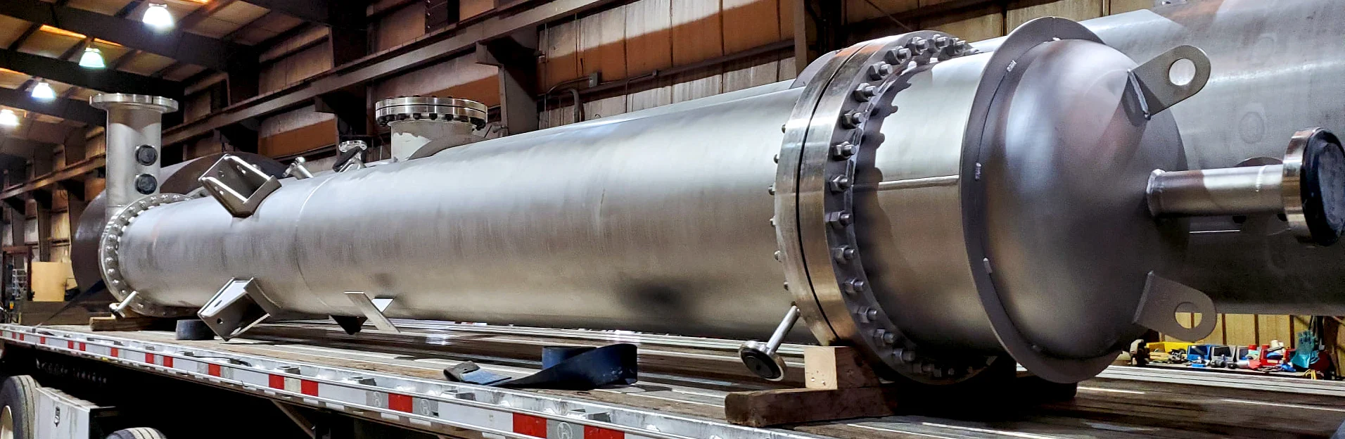
Stainless Heat Exchanger
I. Understanding Seamless Tubes
Seamless tubes differ from welded tubes in that they do not have a welded seam, which can be a weak point in some high-pressure applications. Seamless tubes are initially formed from a solid billet, which is then heated, and subsequently, it is either extruded or drawn over a mandrel to create the tube shape. The absence of seams gives them superior strength and reliability, making them ideal for high-pressure and high-temperature environments.
Common Applications:
Boilers: Seamless tubes are essential in the construction of water-tube and fire-tube boilers, where high temperatures and pressures are present.
Heat Exchangers: Used to transfer heat between two fluids, seamless tubes in heat exchangers must resist corrosion and maintain thermal efficiency.
Condensers: Seamless tubes help condense steam into water in power generation and refrigeration systems.
Superheaters: Seamless tubes are used to superheat steam in boilers, enhancing the efficiency of turbines in power plants.
Air Preheaters: These tubes transfer heat from flue gases to air, improving boiler efficiency.
Economizers: Seamless tubes in economizers preheat the feedwater using waste heat from boiler exhaust, boosting thermal efficiency.
Boilers, heat exchangers, condensers, superheaters, air preheaters, and economizers are integral components in several industries, particularly those involved in heat transfer, energy production, and fluid management. Specifically, these components find primary use in the following industries:
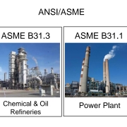
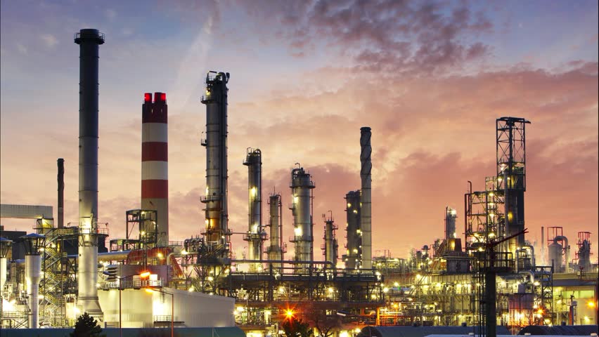
1. Power Generation Industry
Boilers: Used in power plants to convert chemical energy into thermal energy, often for steam generation.
Superheaters, Economizers, and Air Preheaters: These components improve efficiency by preheating the combustion air, recovering heat from exhaust gases, and further heating the steam.
Heat Exchangers and Condensers: Used for cooling and heat recovery in thermal power plants, particularly in steam-driven turbines and cooling cycles.
2. Oil & Gas Industry
Heat Exchangers: Crucial in refining processes, where heat is transferred between fluids, such as in crude oil distillation or in offshore platforms for gas processing.
Boilers and Economizers: Found in refineries and petrochemical plants for steam generation and energy recovery.
Condensers: Used to condense gases into liquids during the distillation processes.
3. Chemical Industry
Heat Exchangers: Used extensively to heat or cool chemical reactions, and to recover heat from exothermic reactions.
Boilers and Superheaters: Used to produce the steam required for various chemical processes, and to provide energy for distillation and reaction steps.
Air Preheaters and Economizers: Improve efficiency in energy-intensive chemical processes by recovering heat from exhaust gases and reducing fuel consumption.
4. Marine Industry
Boilers and Heat Exchangers: Essential in marine vessels for steam generation, heating, and cooling systems. Marine heat exchangers are often used to cool the ship’s engines and generate power.
Condensers: Used to convert exhaust steam back into water for reuse in the ship’s boiler systems.
5. Food and Beverage Industry
Heat Exchangers: Commonly used for pasteurization, sterilization, and evaporative processes.
Boilers and Economizers: Used to produce steam for food processing operations and to recover heat from the exhaust to save on fuel consumption.
6. HVAC (Heating, Ventilation, and Air Conditioning)
Heat Exchangers and Air Preheaters: Used in HVAC systems for efficient heat transfer between fluids or gases, providing heating or cooling for buildings and industrial facilities.
Condensers: Used in air conditioning systems to reject heat from the refrigerant.
7. Pulp and Paper Industry
Boilers, Heat Exchangers, and Economizers: Provide steam and heat recovery in processes such as pulping, paper drying, and chemical recovery.
Superheaters and Air Preheaters: Enhance energy efficiency in the recovery boilers and the overall heat balance of paper mills.
8. Metallurgical and Steel Industry
Heat Exchangers: Used for cooling hot gases and liquids in steel production and metallurgical processes.
Boilers and Economizers: Provide heat for various processes like blast furnace operation, heat treatment, and rolling.
9. Pharmaceutical Industry
Heat Exchangers: Used for controlling temperature during drug production, fermentation processes, and sterile environments.
Boilers: Generate the steam required for sterilization and heating of pharmaceutical equipment.
10. Waste-to-Energy Plants
Boilers, Condensers, and Economizers: Used for converting waste into energy through combustion, while recovering heat to improve efficiency.
Now, let’s dive into the materials that make seamless tubes suitable for these demanding applications.
II. Carbon Steel Tubes for Boiler and Heat Exchanger
Carbon steel is one of the most widely used materials for seamless tubes in industrial applications, primarily due to its excellent strength, as well as its affordability and widespread availability. Carbon steel tubes offer moderate temperature and pressure resistance, making them suitable for a wide range of applications.
Properties of Carbon Steel:
High Strength: Carbon steel tubes can withstand significant pressure and stress, making them ideal for use in boilers and heat exchangers.
Cost-Effective: Compared to other materials, carbon steel is relatively inexpensive, which makes it a popular choice in large-scale industrial applications.
Moderate Corrosion Resistance: While carbon steel is not as corrosion-resistant as stainless steel, it can be treated with coatings or linings to improve its longevity in corrosive environments.
Main Standards and Grades:
ASTM A179: This standard covers seamless cold-drawn low-carbon steel tubes used for heat exchanger and condenser applications. These tubes have excellent heat transfer properties and are commonly used in low to moderate-temperature and pressure applications.
ASTM A192: Seamless carbon steel boiler tubes designed for high-pressure service. These tubes are used in steam generation and other high-pressure environments.
ASTM A210: This standard covers seamless medium-carbon steel tubes for boiler and superheater applications. The A-1 and C grades offer varying levels of strength and temperature resistance.
ASTM A334 (Grades 1, 3, 6): Seamless and welded carbon steel tubes designed for low-temperature service. These grades are used in heat exchangers, condensers, and other low-temperature applications.
EN 10216-2 (P235GH, P265GH TC1/TC2): European standard for seamless steel tubes used in pressure applications, particularly in boilers and high-temperature service.
Carbon steel tubes are an excellent choice for Boiler and Heat Exchanger applications where high strength and moderate corrosion resistance are required. However, for applications involving not only extremely high temperatures but also harsh corrosive environments, alloy or stainless steel tubes are often preferred due to their superior resistance and durability.
III. Alloy Steel Tubes for Boiler and Heat Exchanger
Alloy steel tubes are designed for high-temperature and high-pressure Boiler and Heat exchanger applications. These tubes are alloyed with elements like chromium, molybdenum, and vanadium to enhance their strength, hardness, and resistance to corrosion and heat. Alloy steel tubes are widely used in critical applications, such as superheaters, economizers, and high-temperature heat exchangers, due to their exceptional strength and resistance to heat and pressure.
Properties of Alloy Steel:
High Heat Resistance: Alloying elements such as chromium and molybdenum improve the high-temperature performance of these tubes, making them suitable for applications with extreme temperatures.
Improved Corrosion Resistance: Alloy steel tubes offer better resistance to oxidation and corrosion compared to carbon steel, particularly in high-temperature environments.
Enhanced Strength: Alloying elements also increase the strength of these tubes, allowing them to withstand high pressure in boilers and other critical equipment.
Main Standards and Grades:
ASTM A213 (Grades T5, T9, T11, T22, T91, T92): This standard covers seamless ferritic and austenitic alloy-steel tubes for use in boilers, superheaters, and heat exchangers. The grades differ in their alloying composition and are selected based on the specific temperature and pressure requirements.
T5 and T9: Suitable for moderate to high-temperature service.
T11 and T22: Commonly used in high-temperature applications, offering improved heat resistance.
T91 and T92: Advanced high-strength alloys designed for ultra-high-temperature service in power plants.
EN 10216-2 (16Mo3, 13CrMo4-5, 10CrMo9-10, 15NiCuMoNb5-6-4, X20CrMoV11-1): European standards for seamless alloy steel tubes used in high-temperature applications. These tubes are commonly used in boilers, superheaters, and economizers in power plants.
16Mo3: An alloy steel with good high-temperature properties, suitable for use in boilers and pressure vessels.
13CrMo4-5 and 10CrMo9-10: Chromium-molybdenum alloys that offer excellent heat and corrosion resistance for high-temperature applications.
Alloy steel tubes are the go-to option for high-temperature and high-pressure environments where carbon steel may not provide sufficient performance for the Boiler and Heat Exchanger.
IV. Stainless Steel Tubes for Boiler and Heat Exchanger
Stainless steel tubes offer exceptional corrosion resistance, making them ideal for Boiler and Heat Exchanger applications involving corrosive fluids, high temperatures, and harsh environments. They are widely used in heat exchangers, superheaters, and boilers, where, in addition to corrosion resistance, high-temperature strength is also required for optimal performance.
Properties of Stainless Steel:
Corrosion Resistance: Stainless steel’s resistance to corrosion comes from its chromium content, which forms a protective oxide layer on the surface.
High Strength at Elevated Temperatures: Stainless steel maintains its mechanical properties even at high temperatures, making it suitable for superheaters and other heat-intensive applications.
Long-Term Durability: Stainless steel’s resistance to corrosion and oxidation ensures a long service life, even in harsh environments.
Main Standards and Grades:
ASTM A213 / ASTM A249: These standards cover seamless and welded stainless steel tubes for use in boilers, superheaters, and heat exchangers. Common grades include:
TP304 / TP304L (EN 1.4301 / 1.4307): Austenitic stainless steel grades are widely used for their corrosion resistance and strength.
TP310S / TP310MoLN (EN 1.4845 / 1.4466): High-temperature stainless steel grades with excellent oxidation resistance.
TP316 / TP316L (EN 1.4401 / 1.4404): Molybdenum-bearing grades with enhanced corrosion resistance, particularly in chloride environments.
TP321 (EN 1.4541): Stabilized stainless steel grade used in high-temperature environments to prevent intergranular corrosion.
TP347H / TP347HFG (EN 1.4550 / 1.4961): High-carbon, stabilized grades for high-temperature applications such as superheaters and boilers.
UNS N08904 (904L) (EN 1.4539): Super austenitic stainless steel with excellent corrosion resistance, particularly in acidic environments.
ASTM A269: Covers seamless and welded austenitic stainless steel tubes for general corrosion-resistant service.
ASTM A789: Standard for duplex stainless steel tubes, offering a combination of excellent corrosion resistance and high strength.
UNS S31803, S32205, S32750, S32760: Duplex and super duplex stainless steel grades, offering superior corrosion resistance, especially in chloride-containing environments.
EN 10216-5: European standard covering stainless steel seamless tubes, including the following grades:
1.4301 / 1.4307 (TP304 / TP304L)
1.4401 / 1.4404 (TP316 / TP316L)
1.4845 (TP310S)
1.4466 (TP310MoLN)
1.4539 (UNS N08904 / 904L)
Stainless steel tubes are highly versatile and are used in a wide range of applications, including heat exchangers, boilers, and superheaters, where both corrosion resistance and high-temperature strength are not only required but also essential for optimal performance.
V. Nickel-based alloys for Boiler and Heat Exchanger
Nickel-based alloys are among the most corrosion-resistant materials available and are commonly used in Boiler and Heat exchanger applications involving extreme temperatures, corrosive environments, and high-pressure conditions. Nickel alloys provide outstanding resistance to oxidation, sulfidation, and carburization, making them ideal for heat exchangers, boilers, and superheaters in harsh environments.
Properties of Nickel-Based Alloys:
Exceptional Corrosion Resistance: Nickel alloys resist corrosion in acidic, alkaline, and chloride environments.
High-Temperature Stability: Nickel alloys maintain their strength and corrosion resistance even at elevated temperatures, making them suitable for high-temperature applications.
Oxidation and Sulfidation Resistance: Nickel alloys are resistant to oxidation and sulfidation, which can occur in high-temperature environments involving sulfur-bearing compounds.
Main Standards and Grades:
ASTM B163 / ASTM B407 / ASTM B444: These standards cover nickel-based alloys for seamless tubes used in boilers, heat exchangers, and superheaters. Common grades include:
Inconel 600 / 601: Excellent resistance to oxidation and high-temperature corrosion, making these alloys ideal for superheaters and high-temperature heat exchangers.
Inconel 625: Offers superior resistance to a wide range of corrosive environments, including acidic and chloride-rich environments.
Incoloy 800 / 800H / 800HT: Used in high-temperature applications due to their excellent resistance to oxidation and carburization.
Hastelloy C276 / C22: These nickel-molybdenum-chromium alloys are known for their outstanding corrosion resistance in highly corrosive environments, including acidic and chloride-containing media.
ASTM B423: Covers seamless tubes made from nickel-iron-chromium-molybdenum alloys such as Alloy 825, which offers excellent resistance to stress corrosion cracking and general corrosion in various environments.
EN 10216-5: European standard for nickel-based alloys used in seamless tubes for high-temperature and corrosive applications, including grades such as:
2.4816 (Inconel 600)
2.4851 (Inconel 601)
2.4856 (Inconel 625)
2.4858 (Alloy 825)
Nickel-based alloys are often chosen for critical applications where corrosion resistance and high-temperature performance are essential, such as in power plants, chemical processing, and oil and gas refineries Boiler and Heat Exchanger.
VI. Titanium and Zirconium Alloys for Boiler and Heat Exchanger
Titanium and zirconium alloys offer a unique combination of strength, corrosion resistance, and lightweight properties, making them ideal for specific applications in heat exchangers, condensers, and boilers.
Properties of Titanium Alloys:
High Strength-to-Weight Ratio: Titanium is as strong as steel but significantly lighter, making it suitable for weight-sensitive applications.
Excellent Corrosion Resistance: Titanium alloys are highly resistant to corrosion in seawater, acidic environments, and chloride-containing media.
Good Heat Resistance: Titanium alloys maintain their mechanical properties at elevated temperatures, making them suitable for heat exchanger tubes in power plants and chemical processing.
Properties of Zirconium Alloys:
Outstanding Corrosion Resistance: Zirconium alloys are highly resistant to corrosion in acidic environments, including sulfuric acid, nitric acid, and hydrochloric acid.
High-Temperature Stability: Zirconium alloys maintain their strength and corrosion resistance at elevated temperatures, making them ideal for high-temperature heat exchanger applications.
Main Standards and Grades:
ASTM B338: This standard covers seamless and welded titanium alloy tubes for use in heat exchangers and condensers. Common grades include:
Grade 1 / Grade 2: Commercially pure titanium grades with excellent corrosion resistance.
Grade 5 (Ti-6Al-4V): A titanium alloy with enhanced strength and high-temperature performance.
ASTM B523: Covers seamless and welded zirconium alloy tubes for use in heat exchangers and condensers. Common grades include:
Zirconium 702: A commercially pure zirconium alloy with outstanding corrosion resistance.
Zirconium 705: An alloyed zirconium grade with improved mechanical properties and high-temperature stability.
Titanium and zirconium alloys are commonly used in highly corrosive environments such as seawater desalination plants, chemical processing industries, and nuclear power plants Boiler and Heat Exchanger due to their superior corrosion resistance and lightweight properties.
VII. Copper and Copper Alloys for Boiler and Heat Exchanger
Copper and its alloys, including brass, bronze, and copper-nickel, are widely used in heat exchangers, condensers, and boilers due to their excellent thermal conductivity and corrosion resistance.
Properties of Copper Alloys:
Excellent Thermal Conductivity: Copper alloys are known for their high thermal conductivity, making them ideal for heat exchangers and condensers.
Corrosion Resistance: Copper alloys resist corrosion in water, including seawater, making them suitable for marine and desalination applications.
Antimicrobial Properties: Copper alloys have natural antimicrobial properties, making them suitable for applications in healthcare and water treatment.
Main Standards and Grades:
ASTM B111: This standard covers seamless copper and copper-alloy tubes for use in heat exchangers, condensers, and evaporators. Common grades include:
C44300 (Admiralty Brass): A copper-zinc alloy with good corrosion resistance, particularly in seawater applications.
C70600 (Copper-Nickel 90/10): A copper-nickel alloy with excellent corrosion resistance in seawater and marine environments.
C71500 (Copper-Nickel 70/30): Another copper-nickel alloy with higher nickel content for enhanced corrosion resistance.
Copper and copper alloys are widely used in marine Boiler and Heat Exchanger applications, power plants, and HVAC systems due to their excellent thermal conductivity and resistance to seawater corrosion.
In addition to the boiler and heat exchanger, condensers, superheaters, air preheaters, and economizers are also vital components that significantly optimize energy efficiency. For instance, the condenser cools the exhaust gases from both the boiler and heat exchanger, while the superheater, on the other hand, increases the steam temperature for improved performance. Meanwhile, the air preheater utilizes exhaust gases to heat incoming air, thereby further enhancing the overall efficiency of the boiler and heat exchanger system. Lastly, economizers play a crucial role by recovering waste heat from flue gases to preheat water, which ultimately reduces energy consumption and boosts the efficiency of both the boiler and heat exchanger.
VIII. Conclusion: Choosing the Right Materials for the Boiler and Heat Exchanger
Seamless tubes are integral to the performance of boilers, heat exchangers, condensers, superheaters, air preheaters, and economizers in industries such as power generation, oil and gas, and chemical processing. The choice of material for seamless tubes depends on the specific application requirements, including temperature, pressure, corrosion resistance, and mechanical strength.
Carbon steel offers affordability and strength for moderate temperature and pressure applications.
Alloy steel provides superior high-temperature performance and strength in boilers and superheaters.
Stainless steel delivers excellent corrosion resistance and durability in heat exchangers and superheaters.
Nickel-based alloys are the best choice for extremely corrosive and high-temperature environments.
Titanium and zirconium alloys are ideal for lightweight and highly corrosive applications.
Copper and copper alloys are preferred for their thermal conductivity and corrosion resistance in heat exchangers and condensers.
Boiler and heat exchanger systems play a crucial role in various industries by efficiently transferring heat from one medium to another. A boiler and heat exchanger work together to generate and transfer heat, providing essential heat for steam production in power plants and manufacturing processes.
By understanding the properties and applications of these materials, engineers and designers can make informed decisions, ensuring the safe and efficient operation of their equipment. When selecting materials for the Boiler and Heat Exchanger, it is crucial to consider the specific requirements of your application. Additionally, you should consult the relevant standards to ensure compatibility and optimal performance.