ZAM Coated Steel for Photovoltaic Brackets

Zinc-Aluminum-Magnesium (ZAM) vs Hot-dip galvanizing (HDG)

Definition

What is Zinc-Aluminum-Magnesium (ZAM)?

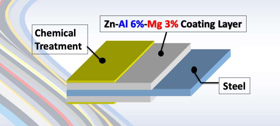
Zinc-aluminum-magnesium (ZAM) is a high-performance metallic coating applied to steel designed to offer superior corrosion resistance, durability, and heat resistance compared to traditional galvanizing (zinc-only coatings). The coating combines zinc (Zn), aluminum (Al), and magnesium (Mg), which provides unique advantages in various applications.

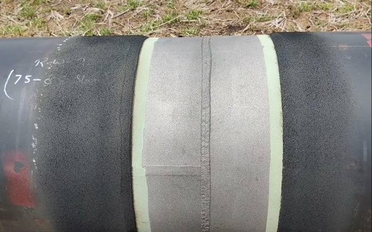
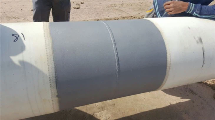
ZAM Coating

ZAM Coating

What is Hot-dip galvanizing? (HDG)?

Hot-dip galvanization is a form of galvanization. It is the process of coating iron and steel with zinc, which alloys with the base metal surface when immersing the metal in a bath of molten zinc at a temperature of around 450 °C (842 °F). When exposed to the atmosphere, the pure zinc (Zn) reacts with oxygen (O2) to form zinc oxide (ZnO), which further reacts with carbon dioxide (CO2) to form zinc carbonate (ZnCO3), a usually dull grey, fairly strong material that protects the steel underneath from further corrosion in many circumstances.

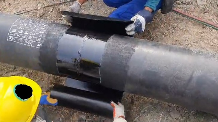
Hot-dip Galvanizing

Hot-dip Galvanizing

Main Differences: Zinc-Aluminum-Magnesium (ZAM) vs Hot-dip galvanizing (HDG)

The comparison between zinc-aluminum-magnesium (ZAM) and hot-dip galvanizing (HDG) revolves around their coating composition, corrosion resistance, applications, cost, and environmental impact. Below is a detailed comparison to help understand their differences:

1. Coating Composition

Zinc-Aluminum-Magnesium (ZAM):
ZAM coatings are made of a combination of zinc (Zn), aluminum (Al), and magnesium (Mg). Typically, the composition is about 80-90% Zinc, 5-11% Aluminum, and 1-3% Magnesium. Including aluminum and magnesium gives the coating superior properties compared to zinc alone.

Hot-Dip Galvanizing (HDG):
HDG involves immersing steel into a molten bath of zinc (Zn) to form a protective zinc coating. The coating consists almost entirely of zinc, with small amounts of iron from the substrate, forming a zinc-iron alloy layer.

2. Corrosion Resistance

Zinc-Aluminum-Magnesium (ZAM):
Superior corrosion resistance compared to hot-dip galvanized steel. Adding aluminum increases the coating’s resistance to high temperatures and oxidation, while magnesium improves its resistance to corrosion in harsh environments like coastal, industrial, and chemical settings. ZAM has self-healing properties—if the coating is damaged, the magnesium component reacts with moisture to help prevent further corrosion.

Hot-Dip Galvanizing (HDG):
It provides good corrosion resistance but not as high as ZAM, especially in aggressive environments. The zinc coating is sacrificial, meaning it corrodes first to protect the underlying steel, but its effectiveness can be limited in humid, salty, or chemical environments. HDG does not have the advanced self-healing properties that ZAM offers.

3. Durability and Longevity

Zinc-Aluminum-Magnesium (ZAM):
ZAM-coated products can last 2 to 4 times longer than traditional galvanized steel in harsh environments (e.g., coastal areas, chemical plants, etc.). The coating’s enhanced resistance to environmental factors contributes to a longer service life.

Hot-Dip Galvanizing (HDG):
The lifespan of HDG products is good but generally shorter than ZAM, particularly in extreme conditions. HDG can last for many years in less corrosive environments (e.g., mild climates), but its protection may degrade faster in severe environments.

4. Applications

Zinc-Aluminum-Magnesium (ZAM):
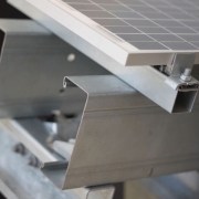
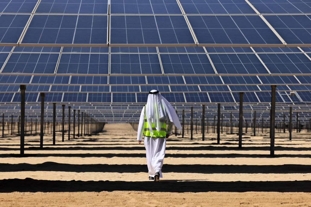
Ideal for harsh environments such as Coastal areas (where saltwater exposure is high), Chemical and industrial environments (where exposure to aggressive substances is every day), Solar panel mounts (due to its superior durability), Heavy-duty industrial applications (e.g., agricultural and mining equipment, steel structures exposed to extreme weather conditions).

Hot-Dip Galvanizing (HDG):
It is commonly used in general construction, automotive industries, outdoor infrastructure, and agricultural applications. It is suitable for general-purpose corrosion protection in outdoor conditions but not recommended for extreme or coastal environments.

5. Cost

Zinc-Aluminum-Magnesium (ZAM):
It is more expensive than traditional hot-dip galvanizing due to the inclusion of aluminum and magnesium and the more advanced coating process. The longer lifespan and lower maintenance costs in harsh environments often justify the higher initial cost.

Hot-Dip Galvanizing (HDG):
It is cheaper than ZAM, making it more suitable for projects where cost-efficiency is a priority and the environment is less aggressive. The relatively lower cost makes it ideal for large-scale production.

6. Environmental Impact

Zinc-Aluminum-Magnesium (ZAM):
The production of ZAM coatings is more environmentally friendly than hot-dip galvanizing, as it involves lower emissions of harmful gases and waste materials. The production process for ZAM generally generates less waste and fewer harmful emissions compared to traditional galvanizing methods.

Hot-Dip Galvanizing (HDG):
It is more environmentally intensive than ZAM, producing more waste gases and wastewater. However, modern improvements in the HDG process have aimed to reduce the environmental footprint, though it remains higher than ZAM.

7. Aesthetic Appearance

Zinc-Aluminum-Magnesium (ZAM):
ZAM has a matte gray finish with a smoother, more uniform appearance. This appearance can be more desirable in specific applications like architectural structures or solar panel mounts.

Hot-Dip Galvanizing (HDG):
HDG often has a shiny or dull metallic finish, depending on the thickness of the coating. While durable, its aesthetic appearance may be less appealing than ZAM’s, especially if the finish is uneven.

8. Ease of Processing and Welding

Zinc-Aluminum-Magnesium (ZAM):
ZAM coatings can be more challenging to process, weld, and paint than traditional galvanized steel, creating issues in some applications.

Hot-Dip Galvanizing (HDG):
HDG products are easier to weld and process than ZAM. However, the zinc coating can make welding and cutting more difficult due to zinc fumes, and special precautions may be required.

Summary Comparison Table: Zinc-Aluminum-Magnesium (ZAM) vs Hot-dip Galvanizing (HDG)

Feature Zinc-Aluminum-Magnesium (ZAM) Hot-Dip Galvanizing (HDG)
Coating Composition Zinc, Aluminum, Magnesium Zinc (with some iron from the substrate)
Corrosion Resistance Superior, especially in harsh environments Good, but less effective in aggressive settings
Durability and Longevity 2-4 times longer than HDG in extreme environments Moderate lifespan, shorter in harsh conditions
Applications Coastal areas, chemical environments, heavy-duty General outdoor infrastructure, agriculture
Cost Higher initial cost Lower initial cost
Environmental Impact Lower emissions and waste Higher emissions and waste
Aesthetic Appearance Matte gray, smoother finish Shiny or dull metallic finish
Ease of Processing It can be more challenging, especially with welding It is more straightforward to process and weld

Conclusion

ZAM is the best choice for extreme environments where superior corrosion resistance and durability are needed. Its long-term performance can justify the higher upfront cost.

HDG remains the go-to solution for general corrosion protection in less aggressive environments, providing a cost-effective and widely available option for most standard applications.

Pipeline vs Piping

Onshore vs Offshore Pipeline and Piping

Introduction

In the realm of energy transportation, the distinction between onshore and offshore pipelines and piping systems plays a crucial role in the efficiency, safety, and environmental impact of resource extraction and distribution. Onshore pipelines, typically situated on land, are designed to transport oil, gas, and other fluids over varying distances, benefiting from relatively more straightforward access for maintenance and monitoring. Conversely, offshore pipelines, laid on the seabed or suspended in water, present unique engineering challenges due to harsh marine conditions and logistical complexities. Understanding the Onshore vs Offshore Pipeline and Piping in design, construction, and operational considerations between these two types of pipelines is essential for optimizing infrastructure development and ensuring sustainable practices in the energy sector.

Definition: Onshore vs Offshore Pipeline and Piping

What is Pipeline?

Pipeline is a long series of pipes, usually of large diameter, running underground, aboveground and underwater, such as a submarine pipeline, and equipped with fittings, such as valves and pumps, to control the flow of large quantities of fluid over long distances. Pipelines have large diameters, making it easy to transport liquids or gases in bulk from one place to another, sometimes for thousands of miles.

Pipeline

Pipeline

What is Piping?

Piping is a system of pipes used to convey fluids (liquids and gases) from one location to another within the designated boundaries or spaces of petrochemical plants, power plants, refineries, etc. It is also equipped with valves and fittings to control the flow of fluids from one facility to another as needed, but only within the plant’s designated boundaries. Never skip these essential topics when taking an online course on piping engineering. Piping diameters range from 1/2 inch to 80 inches, depending on the facility’s design requirements for fluid transportation, usually from one facility to another within the facility’s boundaries.

Piping

Piping

What is Onshore Pipeline?

Onshore pipelines refer to networks of pipelines and related equipment used to transport fluids such as oil, natural gas, water, and chemicals in a land environment. These pipelines are integral to long-distance oil and gas transportation from oil fields to refineries, from natural gas wells to gas stations, and from crude oil and refined oil tank farms, chemical tank farms, LNG tank farms, and aircraft refueling pipeline operations.

Onshore Pipeline

Onshore Pipeline

What is Offshore Pipeline?

Offshore pipelines refer to the network of pipes and related equipment used to transport fluids such as oil, gas, water, and chemicals in an offshore environment. These pipelines are integral to operating offshore oil rigs, platforms and floating production storage and offloading units (FPSOs). The unique conditions of the offshore environment, such as high salinity, extreme temperatures, and strong currents, present significant challenges to the design and maintenance of these systems.

Offshore Pipeline

Offshore Pipeline

Main Differences: Onshore vs Offshore Pipeline and Piping

Comparison Table: Onshore vs Offshore Pipeline and Piping

Specification Onshore Offshore
Pipeline Piping Pipeline Piping
Design Codes – ASME B31.4: Pipeline Transportation Systems for Liquids and Slurries
– ASME B31.8: Gas Transmission and Distribution Piping Systems
ASME B31.3: Process Piping – DNVGL-ST-F101: Submarine pipeline systems
– API RP 1111: Design, Construction, Operation, and Maintenance of Offshore Hydrocarbon Pipelines (Limit state design)
ASME B31.3: Process Piping
Scope Outside plant boundary
(Villages, fields, rivers, canals, railways, highways, cities, deserts, forests, hills, etc.)
Within plant boundary Outside plant boundary Within plant boundary
Type of pipe API Spec 5L: Specification for Line pipes – ASTM
– BS
– API 5L
API Spec 5L: Specification for Line pipes
– DNVGL-ST-F101: Submarine Pipeline Systems
ASTM Standards
Valves – API 6D: Specification for Pipeline and Piping Valves
– Full Bore (FB) Ball Valves are used for pigs.
– BS
– API Standard
– Full bore (FB) and Reduced bore (RB)
– Full bore Valves: for smooth passage of intelligent pigs
– API 6D SS: Specification on Subsea Pipeline Valves
– RB valves
– BS/API standards
Welding – API Std. 1104: Welding of Pipelines and Related Facilities
– Type of welding: Automatic / Semi-Automatic/ Manual
– ASME Sec. IX: Standard for Welding and Brazing Procedures, Welders, Brazers and Welding and Brazing Operators
– Type of welding: Manual (mostly)
– API Std. 1104: Welding of Pipelines and Related Facilities
– Mostly automatic welding on pipelay barge.
– ASME Sec. IX: Standard for Welding and Brazing Procedures, Welders, Brazers and Welding and Brazing Operators
– Manual welding at the fabrication yard.
Weld joint inspection (NDT requirements) 100% by Automatic UT or RT (by using X-Ray) 5% to 100%
(mostly by using gamma rays)
100% by Automatic UT From 10% to 100% as required
Analyses – Wall Thickness Analysis
– Elastic Bend Radius Analysis
– Stability Analysis for Water Bodies/ Marshy Areas
– Horizontal directional drilling design analysis
– Railroad/ Highway Crossing Analysis
– Casing Pipe Analysis for Crossings
– Seismic Analysis
– Piping wall thickness calculation
– Piping Stress Analysis
Static Analysis
Dynamic Analysis
Wind Analysis
Flange Leakage Analysis
Seismic Analysis
– Wall thickness Analysis
– On-bottom Stability
– Span Analysis
– Global Buckling – Lateral and Upheaval
– Pipeline Expansion Analysis
– Riser Design (Span, Stress & Flexibility Analysis)
– Riser Clamp Design
– Pipeline Crossing Design and Analysis
– Deck piping stress analysis
Installation Buried (mostly) Above ground/On rack/slippers/T-postal etc. Subsea (in water on the seabed or buried in the seabed) Deck Platform Piping
(similar to plant)
Special Installations – Across rivers
– Horizontal Directional Drilling (HDD) method
– Micro-tunnelling method
– Across road/ rail/ highway
– Auger boring/ jacking boring method
– Shallow HDD
– Ghats/ Hills
– Modular installations
– Finning
– Studding
– Jacketing
– Spooling inside warehouse
– U/G piping for cooling water
– S-lay Method (for shallow water installation)
– J-Lay Method (for deep water installation)
– Shore pull/ barge pull near Land Fall Point (LFP)
Along with the deck structure
Special Equipment – Sectionalizing Valves (Remote operated)
– Insulating Joints
– Scraper Launcher/ Receiver
– Stem Extended Valves (for buried valves)
– Flow Tee
– Long Radius bends (R=6D)
– Cold field bends (R = 30D or 40D)
– Expansion Joints
– Motor Operator Valves (MOV)
– Cryogenic Valves
– Springs
– Subsea Isolation Valve (SSIV)
– LR Bends
– Flow tee
– Pipeline End Manifold (PLEM)
– Single Point Mooring (SPM) system
– Submarine hoses
– Floating hoses
– Cables and umbilical installation
– Piggy-back pipelines
Not Applicable
Survey – Topographical Survey
(all along the pipeline route)
– Geotechnical investigation
(all along the pipeline route)
– Soil resistivity survey
(all along the pipeline route)
– Hydrological Survey for water bodies (for scour depth calculation)
– Cadastral Survey (for RoU acquisition)
– Wind profile from meteorology
– Seismic study of plot
– Geophysical survey/ Bathymetric Survey by using side scan sonar, sub-bottom profiler, and echo-sounder
– Met-Ocean data collection
– Geotechnical data of the pipeline route
Not Applicable
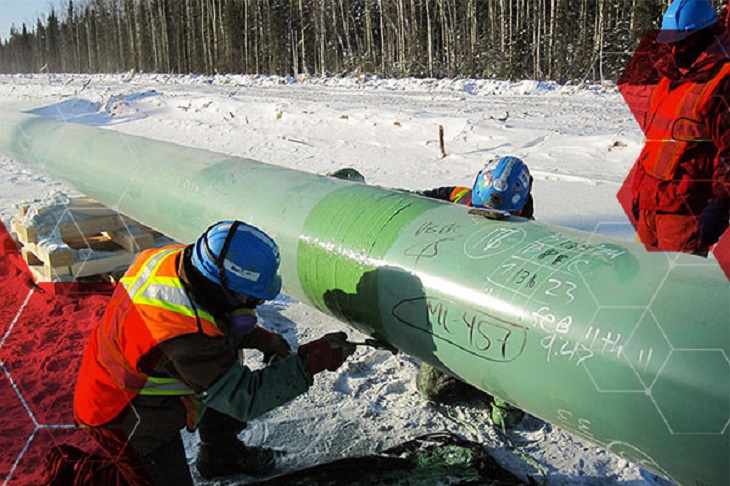
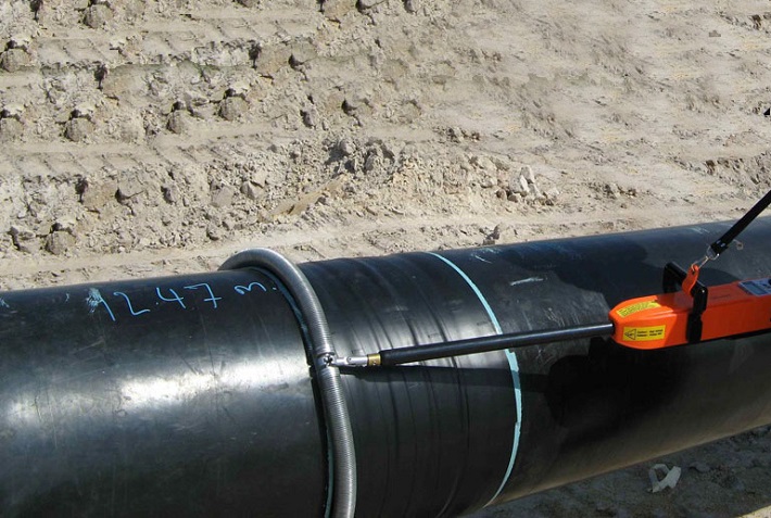
Corrosion Protection Coating Three Layer Polyethylene (3LPE) coating
Three Layer Polypropylene (3LPP) coating
Fusion bonded epoxy (FBE) coating
– Coal tar enamel (CTE) Coating
Painting Coatings such as:
– Coal Tar Enamel Coating (CTE)
Three-layer polyethylene coating (3LPE)
Three-layer polypropylene coating (3LPP)
– Double-layer fusion bonded epoxy coating (2FBE)
Painting
Cathodic Protection System – Impressed Current Cathodic Protection (ICCP) system
– Sacrificial Anode (limited locations)
Not applicable Sacrificial Anodic Cathodic Protection (SACP) system Not Applicable
Hydrostatic testing – Gauge Plate run of 95% of the ID of the highest pipe thickness
– Test Pressure
Minimum: 1.25 times of Design Pressure (for liquid pipelines)
1.25 to 1.5 times of Design Pressure (for gas pipelines)
Maximum: Pressure equivalent to Hoop stress of 95% of SMYS of pipe material
– Hold period: 24 hours
– No gauge plate run is done. Generally, cardboard blasting is done to clean the piping.
– Test Pressure
Minimum: 1.5 × Design Pressure × Temperature Factor
Maximum: Based on line schedule
– Hold period: 2 – 6 hours
– Gauge Plate run of 95% of the ID of the highest pipeline thickness.
– Test Pressure
Minimum: 1.25 times x Design Pressure
– Hold period: 24 hours
– No gauging is done.
– Test Pressure
Maximum: As per line schedule
– Hold period: 2 hours
Preservation – Preservation of pipeline with corrosion-inhibited water or by filling of inert gas (N2) Not applicable
Pigging Intelligent Pigging Not applicable Compliant Not applicable
Machines/Equipment required for installation – Trencher
– Backhoe/ Excavator
– Side Boom
– Cold field bending machine
– Holiday Detection Machines
– Pneumatic/ Hydraulic Internal Clamps
Crane/ Hydra – Pipelay Barge
– Derrick Barge
– Diving support vessel
– Dynamic Positioning (DP) barge (for deepwater)
Pre-fabricated deck piping

Conclusion: Onshore vs Offshore Pipeline and Piping

In summary, Onshore pipelines are usually buried or erected on land to transport oil, natural gas, drinking water, sewage, seawater, slurry, etc. Onshore piping is typically erected in petrochemical plants, power plants, refineries, fire protection systems, water treatment systems, etc., while Offshore pipelines are buried on the seabed. Offshore piping typically consists of transmission and structural support pipeline systems on offshore drilling platforms. Special offshore equipment includes underwater isolation valves, tees, and submarine hoses. Offshore surveys include geophysics, bathymetry, and ocean data collection, while onshore surveys focus on topographic and geotechnical engineering studies.

L80-9Cr vs L80-13Cr

L80-9Cr vs L80-13Cr: Something You Need to Know

Choosing the proper casing and tubing materials can ensure safety and efficiency in oil and gas drilling and exploration. L80-9Cr and L80-13Cr are two alloy steel grades commonly used in petroleum casing and tubing. Each grade has unique characteristics and applications. L80-9Cr vs L80-13Cr, this article will delve into the difference between these materials to help you make an informed decision.

1. Overview of L80 Grade

L80 is an alloy steel used in the oil and gas sector. It is known for its good strength and corrosion resistance. It is typically employed in high-temperature and high-pressure environments and is suitable for both oil and gas production.

1.1 L80-9Cr

Composition: Contains 9% chromium, enhancing the material’s oxidation resistance at high temperatures.
Characteristics:
Corrosion Resistance: It performs well in CO2 environments, making it suitable for acidic gas pipelines.
Mechanical Strength: Provides good strength and is suitable for high-temperature operations.
Applications: Commonly used in high-temperature gas pipelines in oil fields.

1.2 L80-13Cr

Composition: Contains 13% chromium, offering higher corrosion resistance.
Characteristics:
Corrosion Resistance: Exhibits superior performance in environments with H2S and CO2, suitable for extreme conditions.
Mechanical Strength: Offers higher strength and is ideal for complex operational environments.
Applications: Used in high-corrosion environments and deep well operations.

L80-9Cr vs L80-13Cr

L80-9Cr and L80-13Cr Casing and Tubing in Oil and Gas Drilling and Exploration

2. Comparison: L80-9Cr vs L80-13Cr

2.1 Chemical Composition

Standard Grade C Si Mn P S Cr Mo Ni Cu
API 5CT L80-9Cr ≤ 0.15 ≤ 1.00 0.30-0.60 ≤ 0.020 ≤ 0.010 8.00-10.00 0.90-1.10 ≤ 0.50 ≤ 0.25
L80-13Cr 0.15-0.22 ≤ 1.00 0.25-1.00 ≤ 0.020 ≤ 0.010 12.00-14.00 ≤ 0.50 ≤ 0.25

2.2 Mechanical Properties

Standard Grade Yield Strength (Mpa) Tensile Strength (Mpa) Elongation (%) Hardness max
min. max. min. min. HRC HBW
API 5CT L80-9Cr 552 655 655 API 5CT
Table C.7
23 241
L80-13Cr 552 655 655 23 241

2.3 Impact Test

Standard Grade Sharpy Impact Energy (J)
Coupling Pipe Body
API 5CT L80-9Cr L-10-40-0 T-10-20-0 L-10-27-0 T-10-14-0
L80-13Cr L-10-40-0 T-10-20-0 L-10-27-0 T-10-14-0

2.4 Corrosion Resistance

L80-9Cr: The 9% chromium content provides moderate corrosion resistance, suitable for environments with low to moderate concentrations of H₂S (hydrogen sulfide) or CO₂ (carbon dioxide), typically seen in less aggressive environments.

L80-13Cr: The 13% chromium content provides enhanced resistance to sour service (i.e., environments with high levels of H₂S) and high CO₂ environments. It’s better for harsher conditions like deep wells or offshore drilling.

2.5 Temperature and Sour Service

L80-9Cr: Generally suitable for moderate-temperature environments.

L80-13Cr: Can withstand higher temperatures and is better equipped for sour service conditions with high concentrations of H₂S or CO₂.

2.6 Cost

L80-9Cr: Due to its lower chromium content, L80-9Cr is less expensive than L80-13Cr. If the environment is not highly corrosive or sour, L80-9Cr could be a more cost-effective option.

L80-13Cr: More expensive but provides superior resistance in harsh conditions, potentially reducing maintenance costs or failures over time.

2.7 Applications

L80-9Cr: Suitable in wells with moderate temperature, pressure, and sour gas conditions. Often used in conventional oil and gas wells or less aggressive service environments.

L80-13Cr: Ideal for high-pressure wells with harsh environmental conditions, particularly in sour gas service, deep wells, or offshore oil & gas operations where high corrosion resistance is critical.

Crude Steel Production

Crude Steel Production in September 2024

In September 2024, the world crude steel production for the 71 countries reporting to the World Steel Association (world steel) was 143.6 million tonnes (Mt), a 4.7% decrease from September 2023.

crude steel production

crude steel production

Crude steel production by region

Africa produced 1.9 Mt in September 2024, up 2.6% on September 2023. Asia and Oceania produced 105.3 Mt, down 5.0%. The EU (27) produced 10.5 Mt, up 0.3%. Europe, Other produced 3.6 Mt, up 4.1%. The Middle East produced 3.5 Mt, down 23.0%. North America produced 8.6 Mt, down 3.4%. Russia & other CIS + Ukraine produced 6.8 Mt, down 7.6%. South America produced 3.5 Mt, up 3.3%.

Table 1. Crude steel production by region

Region Sep 2024 (Mt) % change Sep 24/23 Jan-Sep 2024 (Mt) % change Jan-Sep 24/23
Africa 1.9 2.6 16.6 2.3
Asia and Oceania 105.3 -5 1,032.00 -2.5
EU (27) 10.5 0.3 97.8 1.5
Europe, Other 3.6 4.1 33.1 7.8
Middle East 3.5 -23 38.4 -1.5
North America 8.6 -3.4 80 -3.9
Russia & other CIS + Ukraine 6.8 -7.6 64.9 -2.5
South America 3.5 3.3 31.4 0
Total 71 countries 143.6 -4.7 1,394.10 -1.9

The 71 countries included in this table accounted for approximately 98% of total world crude steel production in 2023.

Regions and countries covered by the table:

  • Africa: Algeria, Egypt, Libya, Morocco, South Africa, Tunisia
  • Asia and Oceania: Australia, China, India, Japan, Mongolia, New Zealand, Pakistan, South Korea, Taiwan (China), Thailand, Vietnam
  • European Union (27): Austria, Belgium, Bulgaria, Croatia, Czechia, Finland, France, Germany, Greece, Hungary, Italy, Luxembourg, Netherlands, Poland, Portugal, Romania, Slovakia, Slovenia, Spain, Sweden
  • Europe, Other: Macedonia, Norway, Serbia, Türkiye, United Kingdom
  • Middle East: Bahrain, Iran, Iraq, Jordan, Kuwait, Oman, Qatar, Saudi Arabia, United Arab Emirates, Yemen
  • North America: Canada, Cuba, El Salvador, Guatemala, Mexico, United States
  • Russia & other CIS + Ukraine: Belarus, Kazakhstan, Russia, Ukraine
  • South America: Argentina, Brazil, Chile, Colombia, Ecuador, Paraguay, Peru, Uruguay, Venezuela

Top 10 steel-producing countries

China produced 77.1 Mt in September 2024, down 6.1% on September 2023. India produced 11.7 Mt, down 0.2%. Japan produced 6.6 Mt, down 5.8%. The United States produced 6.7 Mt, up 1.2%. Russia is estimated to have produced 5.6 Mt, down 10.3%. South Korea produced 5.5 Mt, up 1.3%. Germany produced 3.0 Mt, up 4.3%. Türkiye produced 3.1 Mt, up 6.5%. Brazil produced 2.8 Mt, up 9.9%. Iran is estimated to have produced 1.5 Mt, down 41.2%.

Table 2. Top 10 steel-producing countries

Region  Sep 2024 (Mt) % change Sep 24/23 Jan-Sep 2024 (Mt) % change Jan-Sep 24/23
China 77.1 -6.1 768.5 -3.6
India 11.7 -0.2 110.3 5.8
Japan 6.6 -5.8 63.3 -3.2
United States 6.7 1.2 60.3 -1.6
Russia 5.6 e -10.3 54 -5.5
South Korea 5.5 1.3 48.1 -4.6
Germany 3 4.3 28.4 4
Türkiye 3.1 6.5 27.9 13.8
Brazil 2.8 9.9 25.2 4.4
Iran 1.5 e -41.2 21.3 -3.1

e – estimated. Ranking of the top 10 producing countries is based on year-to-date aggregate

API 5L vs ISO 3183

Know the Differences: API 5L vs ISO 3183

ISO 3183 and API 5L are standards related to steel pipes, primarily for use in the oil, gas, and other fluid transportation industries. While there is significant overlap between these two standards, API 5L vs ISO 3183, key differences exist in their scope, application, and the organizations behind them.

1. Issuing Organizations: API 5L vs ISO 3183

API 5L: Issued by the American Petroleum Institute (API), this standard is primarily used in the oil and gas industry. It details the technical requirements for steel pipes transporting oil, gas, and water.
ISO 3183: Issued by the International Organization for Standardization (ISO), this standard is internationally recognized and used globally for steel pipes in the oil and gas transportation sector.

2. Scope of Application: API 5L vs ISO 3183

API 5L: Covers steel pipes for transporting petroleum, natural gas, and other fluids under high pressure. It is widely used in North America, especially in the United States.
ISO 3183: This standard primarily focuses on the design, manufacture, and quality control of steel pipes used in oil and gas pipelines, but its use is more international and applicable in various countries worldwide.

3. Key Differences: API 5L vs ISO 3183

Geographic and Market Focus:

API 5L is more tailored to the North American market (particularly the U.S.), while ISO 3183 is internationally applicable and used in many countries worldwide.

Steel Grades and Requirements:

API 5L defines steel grades like L175, L210, L245, and so on, where the number represents the minimum yield strength in megapascals (MPa).
ISO 3183 also defines similar grades but with more detailed requirements regarding material properties, manufacturing processes, and inspection protocols, aligning with international industry practices.
Additional Specifications:
API 5L emphasizes quality control, certification, and production requirements, whereas ISO 3183 covers a broader scope, with international trade in mind, and provides specifications for different conditions, including temperature, environment, and specific mechanical requirements.

4. Technical Requirements: API 5L vs ISO 3183

API 5L specifies steel pipes’ material properties, manufacturing processes, dimensions, testing methods, and quality control. It defines steel grades from L (low strength) to X grades (higher strength), such as X42, X60, and X70.
ISO 3183 covers similar aspects of steel pipe manufacture, including material quality, heat treatment, surface treatment, and pipe ends. It also provides detailed specifications for pipeline design pressure, environmental considerations, and various pipeline accessories.

5. Comparison of Pipe Grades: API 5L vs ISO 3183

API 5L: The grades range from L grades (low yield strength) to X grades (higher yield strength). For example, X60 refers to pipes with a yield strength of 60,000 psi (approximately 413 MPa).
ISO 3183: It uses a similar grading system but may include more detailed classifications and conditions. It also ensures alignment with global pipeline design and operational practices.

6. Compatibility Between Standards:

In many cases, API 5L and ISO 3183 are compatible, meaning that a steel pipe that meets the requirements of API 5L will generally also meet the requirements of ISO 3183 and vice versa. However, specific pipeline projects may adhere to one standard over the other depending on location, client preferences, or regulatory requirements.

7. Conclusion:

API 5L is more common in the United States and surrounding regions. It focuses on the oil and gas pipeline industry, strongly emphasizing production and quality control.
ISO 3183 is an international standard for global oil and gas pipeline projects. Its more detailed, globally aligned requirements ensure broader acceptance in international markets.

Both standards are very similar regarding material, manufacturing, and testing specifications. Still, ISO 3183 tends to have a broader, more globally applicable scope, while API 5L remains more specific to the North American market. The choice between these standards depends on the pipeline project’s geographical location, specifications, and regulatory needs.

Stainless Steel vs Galvanized Steel

Stainless Steel vs Galvanised Steel

Introduction

Stainless Steel vs Galvanized Steel, it’s crucial to consider the environment, required durability, and maintenance needs. Stainless steel offers unmatched corrosion resistance, strength, and visual appeal, making it suitable for demanding applications in harsh environments. Galvanized steel, on the other hand, offers cost-effective corrosion protection for less aggressive settings.

1. Composition and Manufacturing Process

Stainless Steel

Stainless steel is an alloy composed mainly of iron, chromium (at least 10.5%), and sometimes nickel and molybdenum. Chromium forms a protective oxide layer on the surface, giving it excellent corrosion resistance. Different grades, like 304 and 316, vary in alloying elements, providing options for various environments, including extreme temperatures and high salinity.

Galvanized Steel

Galvanized steel is carbon steel coated with a layer of zinc. The zinc layer protects the steel underneath as a barrier against corrosion. The most common galvanizing method is hot-dip galvanizing, where the steel is submerged in molten zinc. Another method is electro-galvanizing, where zinc is applied using an electric current. Both processes enhance corrosion resistance, though they are generally less durable in harsh environments than stainless steel.

2. Corrosion Resistance

Stainless Steel

Stainless steel’s corrosion resistance is inherent due to its alloy composition, which forms a passive chromium oxide layer. Grade 316 stainless steel, which includes molybdenum, provides excellent resistance to corrosion from chlorides, acids, and other aggressive chemicals. It’s a preferred choice in marine, chemical processing, and oil and gas industries, where exposure to corrosive agents is daily.

Galvanized Steel

The zinc layer on galvanized steel provides sacrificial protection; the zinc will corrode before the underlying steel, offering some corrosion resistance. However, this protection is limited, as the zinc layer can degrade over time. While galvanized steel performs adequately in mild environments and general construction, it doesn’t withstand harsh chemicals or saltwater exposure as effectively as stainless steel.

3. Mechanical Properties and Strength

Stainless Steel

Stainless steel is generally more robust than galvanized steel, with higher tensile strength and durability. This makes it ideal for applications that require resilience and reliability under pressure. Stainless steel also offers excellent resistance to impact and wear, which benefits infrastructure and heavy-duty industrial applications.

Galvanized Steel

While galvanized steel’s strength primarily comes from the carbon steel core, it is generally less robust than stainless steel. The added zinc layer doesn’t significantly contribute to its strength. Galvanized steel is suitable for medium-duty applications where corrosion resistance is necessary but not in extreme or high-stress environments.

4. Appearance and Aesthetics

Stainless Steel

Stainless steel has a sleek, shiny appearance and is often desirable in architectural applications and visible installations. Its aesthetic appeal and durability make it a preferred choice for high-visibility structures and equipment.

Galvanized Steel

The zinc layer gives galvanized steel a dull, matte-gray finish less visually appealing than stainless steel. Over time, exposure to weather may lead to a whitish patina on the surface, which can reduce aesthetic appeal, though it doesn’t impact performance.

5. Cost Considerations

Stainless Steel

Stainless steel is typically more expensive due to its alloying elements, chromium and nickel, and complex manufacturing processes. However, its longer lifespan and minimal maintenance can offset the initial cost, especially in demanding environments.

Galvanized Steel

Galvanized steel is more economical than stainless steel, especially for short- to medium-term applications. It’s a cost-effective choice for projects with a limited budget and moderate corrosion resistance needs.

6. Typical Applications

Stainless Steel Applications

Oil and Gas: Used in pipelines, storage tanks, and offshore platforms due to its high corrosion resistance and strength.
Chemical Processing: Excellent for environments where exposure to acidic or caustic chemicals is every day.
Marine Engineering: Stainless steel’s resistance to saltwater makes it suitable for marine applications like docks, vessels, and equipment.
Infrastructure: Ideal for bridges, railings, and architectural structures where durability and aesthetics are essential.

Galvanized Steel Applications

General Construction: Commonly used in building frames, fences, and roofing supports.
Agricultural Equipment: Provides a balance of corrosion resistance and cost-effectiveness for equipment exposed to soil and moisture.
Water Treatment Facilities: Suitable for non-critical water infrastructure, such as piping and storage tanks in low-corrosion environments.
Outdoor Structures: Commonly used in road barriers, guardrails, and poles, where exposure to mild weather conditions is expected.

7. Maintenance and Longevity

Stainless Steel

Stainless steel requires minimal maintenance due to its inherent corrosion resistance. However, in harsh environments, periodic cleaning is recommended to remove salt, chemicals, or deposits that could compromise the protective oxide layer over time.

Galvanized Steel

Galvanized steel requires regular inspection and maintenance to keep the zinc layer intact. If the zinc layer is scratched or degraded, re-galvanizing or additional coatings may be necessary to prevent corrosion. This is particularly important in marine or industrial applications, where the zinc layer is at risk of degrading faster.

8. Example: Stainless Steel vs Galvanized Steel

PROPERTY STAINLESS STEEL (316) GALVANISED STEEL COMPARISON
Mechanism of protection A protective oxide layer that self-repairs in the presence of oxygen, granting long-term corrosion resistance. A protective zinc coating is applied to the steel during manufacturing. When damaged, surrounding zinc cathodically protects the exposed steel. The stainless steel protective layer is more durable and can ‘heal’ itself. Stainless steel protection does not diminish with material loss or thickness reduction.
Appearance Many finishes are available, from very bright electropolished to abrasive linished. Appealing high-quality look and feel. Spangles possible. The surface is not bright and gradually changes to a dull grey with age. Aesthetic design choice.
Surface feel It is very smooth and can be slippery. It has a coarser feel, which becomes more apparent with age. Aesthetic design choice.
Green credentials It may be reused in new structures. After the lifetime of the structure, it is valuable as scrap, and because of its collection value, it has a high recycling rate. Carbon steel is generally scrapped at end-of-life and is less valuable. Stainless steel is extensively recycled both within manufacturing and at end-of-life. All new stainless steel contains a substantial proportion of recycled steel.
Heavy metal runoff Negligible levels. Significant zinc runoff off, especially early in life. Some European highways have been changed to stainless steel railings to avoid environmental zinc contamination.
Lifetime Indefinite, provided surface is maintained. Slow general corrosion until the zinc dissolves. Red rust will appear as the zinc/iron layer corrodes, and finally, the substrate steel. Repair is required before ~2% of the surface has red spots. Clear life-cycle cost benefit for stainless steel if extended life intended. The economic break-even point can be as short as six years, depending on the environment and other factors.
Fire resistance Excellent for austenitic stainless steels with reasonable strength and deflection during fires. Zinc melts and runs, which may cause the failure of adjacent stainless steel in a chemical plant. The carbon steel substrate loses strength and suffers deflection. Stainless steel offers better fire resistance and avoids the risk of molten zinc if galvanised is used.
Welding on site This is a routine for austenitic stainless steels, with care about thermal expansion. Welds can be blended into the surrounding metal surface. Post-weld clean-up and passivation are essential. Carbon steel is readily self-weldable, but zinc must be removed because of fumes. If galvanised and stainless steel are welded together, any zinc residue will embrittle the stainless steel. Zinc-rich paint is less durable than galvanizing. In severe marine environments, crusty rust can appear in three to five years, and steel attacks occur at four years/mm afterward. Short-term durability is similar, but a zinc-rich coating at joins requires upkeep. In severe conditions, galvanized steel will get rough rust—even holes—and possible hand injury, especially from the unseen seaward side.
Contact with damp, porous material (e.g., wooden wedges) in a salty environment. It will likely cause rust stains and crevice attack but not structural failure. Similar to storage stains, it leads to rapid zinc loss and longer-term due to perforation. It is not desirable for either, but it can cause failure at the base of galvanized poles in the long term.
Maintenance It can suffer from tea staining and micro-pitting if not adequately maintained. It can suffer general zinc loss and subsequent corrosion of the steel substrate if not adequately maintained. Rain in open areas or washing in sheltered regions is required for both.