Well Completion: Application and Installation Sequences of OCTG in Oil and Gas Wells

Introduction

Oil and gas exploration and production involve complex equipment and processes. Among these, the proper selection and use of tubular goods—drill pipes, drill collars, drill bits, casing, tubing, sucker rods, and line pipes—are crucial for the efficiency and safety of drilling operations. This blog aims to provide a detailed overview of these components, their sizes, and their sequential use in oil and gas wells.

1. Drill Pipe, Drill Collar, and Drill Bit Sizes

Drill Pipes are the backbone of the drilling operation, transmitting power from the surface to the drill bit while circulating drilling fluid. Common sizes include:

  • 3 1/2 inches (88.9 mm)
  • 4 inches (101.6 mm)
  • 4 1/2 inches (114.3 mm)
  • 5 inches (127 mm)
  • 5 1/2 inches (139.7 mm)

Drill Collars add weight to the drill bit, ensuring it penetrates the rock effectively. Typical sizes are:

  • 3 1/8 inches (79.4 mm)
  • 4 3/4 inches (120.7 mm)
  • 6 1/4 inches (158.8 mm)
  • 8 inches (203.2 mm)

Drill Bits are designed to crush and cut through rock formations. Their sizes vary significantly, depending on the required borehole diameter:

  • 3 7/8 inches (98.4 mm) to 26 inches (660.4 mm)

2. Casing and Tubing Sizes

Casing Pipe stabilizes the borehole, prevents collapse, and isolates different geological formations. It is installed in stages, with each string having a larger diameter than the one inside it:

  • Surface Casing: 13 3/8 inches (339.7 mm) or 16 inches (406.4 mm)
  • Intermediate Casing: 9 5/8 inches (244.5 mm) or 10 3/4 inches (273.1 mm)
  • Production Casing: 7 inches (177.8 mm) or 5 1/2 inches (139.7 mm)

Oil Tubing is inserted inside the casing to transport oil and gas to the surface. Typical tubing sizes include:

  • 1.050 inches (26.7 mm)
  • 1.315 inches (33.4 mm)
  • 1.660 inches (42.2 mm)
  • 1.900 inches (48.3 mm)
  • 2 3/8 inches (60.3 mm)
  • 2 7/8 inches (73.0 mm)
  • 3 1/2 inches (88.9 mm)
  • 4 inches (101.6 mm)

3. Sucker Rod and Tubing Sizes

Sucker Rods connect the surface pumping unit to the downhole pump, enabling the lifting of fluids from the well. They are selected based on the tubing size:

  • For 2 3/8 inches tubing: 5/8 inches (15.9 mm), 3/4 inches (19.1 mm), or 7/8 inches (22.2 mm)
  • For 2 7/8 inches of tubing: 3/4 inches (19.1 mm), 7/8 inches (22.2 mm), or 1 inch (25.4 mm)

4. Line Pipe Sizes

Line Pipes transport the produced hydrocarbons from the wellhead to processing facilities or pipelines. They are chosen based on the production volume:

  • Small Fields: 2 inches (60.3 mm), 4 inches (114.3 mm)
  • Medium Fields: 6 inches (168.3 mm), 8 inches (219.1 mm)
  • Large Fields: 10 inches (273.1 mm), 12 inches (323.9 mm), 16 inches (406.4 mm)

Sequential Use of Tubulars in Oil and Gas Wells

1. Drilling Stage

  • The drilling operation begins with the drill bit breaking through the geological formations.
  • Drill pipes transmit rotary power and drilling fluid to the drill bit.
  • Drill collars add weight to the bit, ensuring it penetrates effectively.

2. Casing Stage

  • Once a certain depth is reached, a casing is installed to protect the borehole and isolate different formations.
  • Surface, intermediate, and production casing strings are run sequentially as drilling progresses.

3. Completion and Production Stage

  • Tubing is installed inside the production casing to facilitate the flow of hydrocarbons to the surface.
  • Sucker rods are used in wells with artificial lift systems, connecting the downhole pump to the surface unit.

4. Surface Transportation Stage

  • Line pipes transport the oil and gas produced from the wellhead to processing facilities or main pipelines.

Conclusion

Understanding these tubular goods’ roles, sizes, and sequential use is essential for efficient and safe oil and gas operations. The proper selection and handling of drill pipes, drill collars, drill bits, casing, tubing, sucker rods, and line pipes ensure the structural integrity of the well and optimize production performance.

By effectively integrating these components, the oil and gas industry can continue to meet the world’s energy needs while maintaining high standards of safety and operational efficiency.

13Cr vs Super 13Cr: A Comparative Analysis

In the challenging landscape of the oil and gas industry, material selection is pivotal to ensuring the longevity and efficiency of operations. Among the myriad of materials available, 13Cr and Super 13Cr stainless steels stand out for their remarkable properties and suitability in demanding environments. These materials have revolutionized the industry, providing exceptional resistance to corrosion and robust mechanical performance. Let’s delve into the unique attributes and applications of 13Cr and Super 13Cr stainless steels.

Understanding 13Cr Stainless Steel

13Cr stainless steel, a martensitic alloy containing approximately 13% chromium, has become a staple in the oil and gas sector. Its composition typically includes small amounts of carbon, manganese, silicon, phosphorus, sulfur, and molybdenum, striking a balance between performance and cost.

Critical Properties of 13Cr:

  • Corrosion Resistance: 13Cr offers commendable resistance to corrosion, particularly in environments containing CO2. This makes it ideal for use in downhole tubing and casing, where exposure to corrosive elements is expected.
  • Mechanical Strength: With moderate mechanical strength, 13Cr provides the necessary durability for various applications.
  • Toughness and Hardness: The material exhibits good toughness and hardness, essential for withstanding the mechanical stresses encountered in the drilling and extraction processes.
  • Weldability: 13Cr is known for its reasonably good weldability, facilitating its use in various applications without significant complications during fabrication.

Applications in Oil and Gas: 13Cr stainless steel is extensively used in the construction of tubing, casing, and other components exposed to mildly corrosive environments. Its balanced properties make it a reliable choice for ensuring the integrity and efficiency of oil and gas operations.

Introducing Super 13Cr: The Enhanced Alloy

Super 13Cr takes the benefits of 13Cr a step further by incorporating additional alloying elements such as nickel and molybdenum. This enhances properties, making it suitable for more aggressive corrosive environments.

Critical Properties of Super 13Cr:

  • Superior Corrosion Resistance: Super 13Cr offers improved corrosion resistance compared to standard 13Cr, particularly in environments containing higher levels of CO2 and the presence of H2S. This makes it an excellent choice for more challenging conditions.
  • Higher Mechanical Strength: The alloy boasts higher mechanical strength, ensuring it can withstand more significant stresses and pressures.
  • Improved Toughness and Hardness: With better toughness and hardness, Super 13Cr provides enhanced durability and longevity in demanding applications.
  • Enhanced Weldability: Super 13Cr’s improved composition results in better weldability, facilitating its use in complex fabrication processes.

Applications in Oil and Gas: Super 13Cr is tailored for use in more aggressive corrosive environments, such as those with higher levels of CO2 and the presence of H2S. Its superior properties are ideal for downhole tubing, casing, and other critical components in challenging oil and gas fields.

Choosing the Right Alloy for Your Needs

The choice between 13Cr and Super 13Cr stainless steels ultimately depends on your oil and gas operations’ specific environmental conditions and performance requirements. While 13Cr provides a cost-effective solution with good corrosion resistance and mechanical properties, Super 13Cr offers enhanced performance for more demanding environments.

Key Considerations:

  • Environmental Conditions: Assess the CO2, H2S, and other corrosive elements in the operating environment.
  • Performance Requirements: Determine the necessary mechanical strength, toughness, and hardness for the specific application.
  • Cost vs. Benefit: Weigh the cost of the material against the benefits of enhanced properties and longer service life.

Conclusion

In the ever-evolving oil and gas industry, selecting materials like 13Cr and Super 13Cr stainless steels is critical to ensuring operations’ reliability, efficiency, and safety. Understanding the unique properties and applications of these alloys allows industry professionals to make informed decisions, ultimately contributing to the success and sustainability of their projects. Whether it’s the balanced performance of 13Cr or the superior attributes of Super 13Cr, these materials continue to play a pivotal role in advancing the capabilities of the oil and gas sector.

Oil Country Tubular Goods (OCTG)

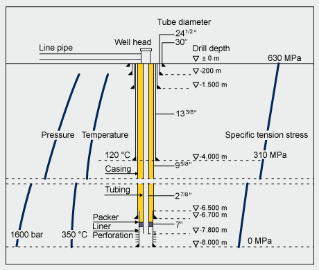
Oil country tubular goods (OCTG) is a family of seamless rolled products consisting of drill pipe, casing, and tubing subjected to loading conditions according to their specific application. (see Figure 1 for a schematic of a deep well):

The Drill Pipe is a heavy seamless tube that rotates the drill bit and circulates drilling fluid. Pipe segments 30 ft (9m) long are coupled with tool joints. The drill pipe is simultaneously subjected to high torque by drilling, axial tension by its dead weight, and internal pressure by purging drilling fluid. Additionally, alternating bending loads due to non-vertical or deflected drilling may be superimposed on these basic loading patterns.
Casing pipe lines the borehole. It is subject to axial tension from its dead weight, internal pressure from fluid purging, and external pressure from surrounding rock formations. The pumped oil or gas emulsion particularly exposes the casing to axial tension and internal pressure.
Tubing is a pipe through which oil or gas is transported from the wellbore. Tubing segments are generally around 30 ft [9 m] long and have a threaded connection on each end.

Corrosion resistance under sour service conditions is a crucial OCTG characteristic, especially for casing and tubing.

Typical OCTG manufacturing processes include (all dimensional ranges are approximate)

Continuous mandrel-rolling and push bench processes for sizes between 21 and 178 mm OD.
Plug mill rolling for sizes between 140 and 406 mm OD.
Cross-roll piercing and pilger rolling for sizes between 250 and 660 mm OD.
These processes typically do not allow the thermomechanical processing customary for the strip and plate products used for the welded pipe. Therefore, high-strength seamless pipe must be produced by increasing the alloying content in combination with a suitable heat treatment, such as quench and tempering.

Figure 1. Schematic of a deep thriving completion

Meeting the fundamental requirement of a fully martensitic microstructure, even at large pipe wall thickness, requires good hardenability. Cr and Mn are the main alloying elements that produce good hardenability in conventional heat-treatable steel. However, the requirement for good sulfide stress cracking (SSC) resistance limits their use. Mn tends to segregate during continuous casting and can form large MnS inclusions that reduce hydrogen-induced cracking (HIC) resistance. Higher levels of Cr can lead to the formation of Cr7C3 precipitates with coarse plate-shaped morphology, which act as hydrogen collectors and crack initiators. Alloying with Molybdenum can overcome the limitations of Mn and Cr alloying. Mo is a much stronger hardener than Mn and Cr, so it can quickly recover the effect of a reduced amount of these elements.

Traditionally, OCTG grades were carbon-manganese steels (up to the 55-ksi strength level) or Mo-containing grades up to 0.4% Mo. In recent years, deep well drilling and reservoirs containing contaminants that cause corrosive attacks have created a strong demand for higher-strength materials resistant to hydrogen embrittlement and SCC. Highly tempered martensite is the structure most resistant to SSC at higher strength levels, and 0.75% Mo concentration produces the optimum combination of yield strength and SSC resistance.

Something You Need to Know: Flange Face Finish

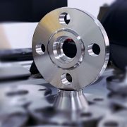
The ASME B16.5 code requires that the flange face (raised face and flat face) has a specific roughness to ensure that this surface is compatible with the gasket and provides a high-quality seal.

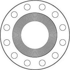
A serrated finish, either concentric or spiral, is required with 30 to 55 grooves per inch and a resultant roughness between 125 and 500 micro inches. This allows for various grades of surface finish to be made available by flange manufacturers for the gasket contact surface of metal flanges.

Flange face finish

Serrated Finish

Stock Finish
The most widely used of any flange surface finish, because practically, is suitable for all ordinary service conditions. Under compression, the soft face from a gasket will embed into this finish, which helps create a seal and a high level of friction is generated between the mating surfaces.

The finish for these flanges is generated by a 1.6 mm radius round-nosed tool at a feed rate of 0.8 mm per revolution up to 12 inches. For sizes 14 inches and larger, the finish is made with a 3.2 mm round-nosed tool at a feed of 1.2 mm per revolution.

Flange face finish - Stock FinishFlange face finish - Stock Finish

Spiral Serrated
This is also a continuous or phonographic spiral groove, but it differs from the stock finish in that the groove typically is generated using a 90-° tool which creates a “V” geometry with 45° angled serration.

Flange face finish - Spiral Serrated

Concentric Serrated
As the name suggests, this finish is comprised of concentric grooves. A 90° tool is used and the serrations are spaced evenly across the face.

Flange face finish - Concentric Serrated

Smooth Finish
This finish shows no visually apparent tool markings. These finishes are typically utilized for gaskets with metal facings such as double jacketed, flat steel, and corrugated metal. The smooth surfaces mate to create a seal and depend on the flatness of the opposing faces to effect a seal. This is typically achieved by having the gasket contact surface formed by a continuous (sometimes called phonographic) spiral groove generated by a 0.8 mm radius round-nosed tool at a feed rate of 0.3 mm per revolution with a depth of 0.05 mm. This will result in a roughness between Ra 3.2 and 6.3 micrometers (125 – 250 micro inch).

Flange face finish - Smooth Finish

SMOOTH FINISH

Is it suitable for spiral gaskets and non-metallic gaskets? For what kind of application is this type?

Smooth finish flanges are more common for low-pressure and/or large-diameter pipelines and are primarily intended for use with solid metal or spiral wound gaskets.

Smooth finishes are usually found on machinery or flanged joints other than pipe flanges. When working with a smooth finish, it is important to consider using a thinner gasket to lessen the effects of creep and cold flow. It should be noted, however, that both a thinner gasket and the smooth finish, in and of themselves, require a higher compressive force (i.e. bolt torque) to achieve the seal.

Machining of gasket faces of flanges to a smooth finish of Ra = 3.2 – 6.3 micrometer (= 125 – 250 microinches AARH)

AARH stands for Arithmetic Average Roughness Height. It is used to measure the roughness (rather smoothness) of surfaces. 125 AARH means 125 micro inches will be the average height of the ups and downs of the surface.

63 AARH is specified for Ring Type Joints.

125-250 AARH (it is called smooth finish) is specified for Spiral Wound Gaskets.

250-500 AARH (it is called stock finish) is specified for soft gaskets such as NON-Asbestos, Graphite sheets, Elastomers, etc. If we use a smooth finish for soft gaskets enough “biting effect” will not occur and hence the joint may develop a leak.

Sometimes AARH is referred also as Ra which stands for Roughness Average and means the same.

API 5L Gr.B Seamless Line Pipe with 3LPE Coating in accordance with CAN CSA Z245.21

Successful Delivery of Order CAN/CSA-Z245.21 3LPE Coated Line Pipe

A customer that we have been following up for 8 years has finally placed an order. The order is for a batch of NPS 3“, NPS 4”, NPS 6“ and NPS 8” diameters, thickness SCH40, single length 11.8M, with 2.5mm thick 3-layer polyethylene coating for corrosion protection, which will be buried in the ground for natural gas transportation.

The pipes are manufactured in accordance with API 5L PSL 1 Gr. B seamless pipe standard and the corrosion protection coating are manufactured in accordance with CAN/CSA-Z245.21 standard.

API 5L Gr.B Seamless Line Pipe with 3LPE Coating in accordance with CAN CSA Z245.21

API 5L Gr.B Seamless Line Pipe with 3LPE Coating in accordance with CAN CSA Z245.21

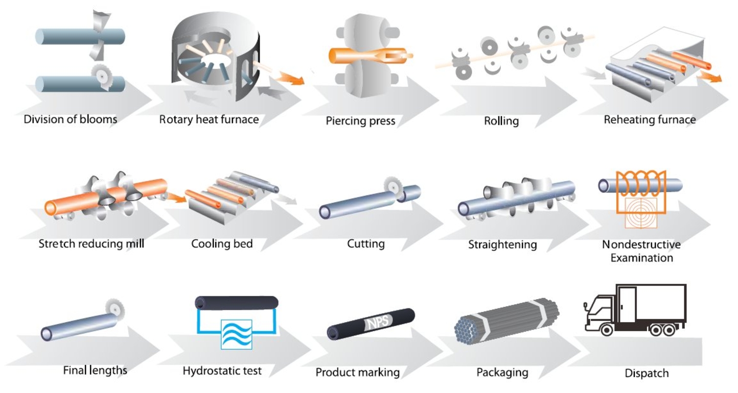
Seamless Pipe Manufacturing Process Chart

Seamless Pipe Manufacturing Process Chart

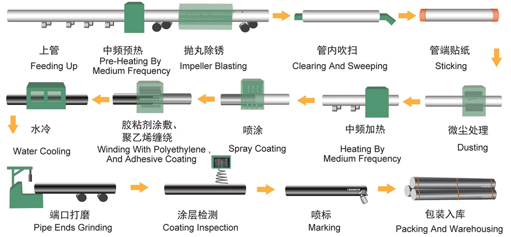
3LPE Coating Manufacturing Process Chart

3LPE Coating Manufacturing Process Chart

Our seamless tubes are rolled in the world’s most advanced PQF mill, which is manufactured by SMS Group in Germany. Our 3LPE coatings are produced in our most advanced coating line in China, ensuring that the specifications of the pipes and coatings fully meet our customers’ requirements.

If you have any demand for 3LPE/3LPP/FBE/LE coated line pipe, please feel free to contact us for a quotation by email at [email protected]. We will strictly control the quality for you and better support you in terms of price and service!

Know the Differences: TPEPE Coating vs 3LPE Coating

TPEPE anticorrosive steel pipe and 3PE anticorrosive steel pipe are upgrading products based on the outer single layer polyethylene and internal epoxy-coated steel pipe, it is the most advanced anticorrosive long-distance steel pipeline buried underground. Do you know what is the difference between TPEPE anticorrosive steel pipe and 3PE anticorrosive steel pipe?


Coating Structure

The outer wall of the TPEPE anticorrosive steel pipe is made of 3PE hot-melt junction winding process.  It is composed of three layers, epoxy resin(bottom layer), adhesive(intermediate layer) and polyethylene(outer layer). The inner wall adopts the anti-corrosion way of thermal spraying epoxy powder, and the powder is evenly coated on the surface of the steel pipe after being heated and fused at high temperature to form a steel-plastic composite layer, which greatly improves the thickness of the coating and the adhesion of the coating, enhances the ability of bump resistance and corrosion resistance, and makes it widely used.

3PE anticorrosive coating steel pipe refers to the three layers of polyolefin outside anti-corrosion steel pipe, its anticorrosion structure generally consists of a three-layer structure, epoxy powder, adhesive and PE, in practice, these three materials mixed melting processing, and steel pipe firmly together, forming a layer of polyethylene (PE) anticorrosive coating, has good corrosion resistance, resistance to moisture permeability and mechanical properties, is widely used in the oil pipeline industry.

Performance Characteristics

Different from the general steel pipe, TPEPE anticorrosive steel pipe has been made internal and external anticorrosive, has a very high sealing, and long-term operation can greatly save energy, reduce costs, and protect the environment. With strong corrosion resistance and convenient construction, its service life is up to 50 years. It also has good corrosion resistance and impact resistance at low temperatures. At the same time, it also has high epoxy strength, good softness of hot melt adhesive, etc., and has high anti-corrosion reliability; In addition, our TPEPE anticorrosive steel pipe is produced in strict accordance with national standard specifications, obtained anticorrosive steel pipe drinking water safety certificate, to ensure the safety of drinking water.

3PE anticorrosive steel pipe made of polyethylene material, this material is marked by good corrosion resistance, and directly extends the service life of anticorrosive steel pipe.

3PE anticorrosive steel pipe because of its different specifications, can be divided into ordinary grade and strengthening grade, the PE thickness of ordinary grade 3PE anticorrosive steel pipe is about 2.0mm, and the PE thickness of the strengthening grade is about 2.7mm. As an ordinary external anticorrosion on casing pipe, the ordinary grade is more than enough. If it is used to directly transport acid, alkali, natural gas and other fluids, try to use the strengthened grade 3PE anti-corrosion steel pipe.

The above is about the difference between TPEPE anticorrosive steel pipe and 3PE anticorrosive steel pipe, mainly reflected in the performance characteristics and application of different, the correct selection of the appropriate anticorrosive steel pipe, plays its due role.