Oil Country Tubular Goods (OCTG)

Oil country tubular goods (OCTG) is a family of seamless rolled products consisting of drill pipe, casing and tubing subjected to loading conditions according to their specific application. (see Figure 1 for a schematic of a deep well):

The Drill Pipe is a heavy seamless tube that rotates the drill bit and circulates drilling fluid. Pipe segments 30 ft (9m) long are coupled with tool joints. Drill pipe is simultaneously subjected to high torque by drilling, axial tension by its dead weight, and internal pressure by purging of drilling fluid. Additionally, alternating bending loads due to non-vertical or deflected drilling may be superimposed on these basic loading patterns.
Casing pipe lines the borehole. It is subject to axial tension by its dead weight, internal pressure by fluid purging, and external pressure by surrounding rock formations. The casing is particularly exposed to axial tension and internal pressure by the pumped oil or gas emulsion.
Tubing is a pipe through which the oil or gas is transported from the wellbore. Tubing segments are generally around 30 ft [9 m] long with a threaded connection on each end.

Corrosion resistance under sour service conditions is a very important OCTG characteristic, especially for casing and tubing.

Typical OCTG manufacturing processes include (all dimensional ranges are approximate)

Continuous mandrel-rolling process and the push bench process for sizes between 21 and 178 mm OD.
Plug mill rolling for sizes between 140 and 406 mm OD.
Cross-roll piercing and pilger rolling for sizes between 250 and 660 mm OD.
These processes typically do not allow the thermomechanical processing customary for the strip and plate products used for the welded pipe. Therefore, high-strength seamless pipe must be produced by increasing the alloying content in combination with a suitable heat treatment such as quench & tempering.

Figure 1. Schematic of a deep well completion

Meeting the fundamental requirement of a fully martensitic microstructure even at large pipe wall thickness requires good hardenability. Cr and Mn are the main alloying elements used to produce good hardenability in conventional heat-treatable steel. However, the requirement for good sulfide stress cracking (SSC) resistance limits their use. Mn tends to segregate during continuous casting and can form large MnS inclusions that reduce hydrogen-induced cracking (HIC) resistance. Higher levels of Cr can lead to the formation of Cr7C3 precipitates with coarse plate-shaped morphology, which act as hydrogen collectors and crack initiators. Alloying with Molybdenum can overcome the limitations of Mn and Cr alloying. Mo is a much stronger hardener than Mn and Cr, so it can easily recover the effect of a reduced amount of these elements.

Traditionally, OCTG grades were carbon-manganese steels (up to the 55-ksi strength level) or Mo-containing grades up to 0.4% Mo. In recent years, deep well drilling and reservoirs containing contaminants that cause corrosive attacks have created a strong demand for higher-strength materials resistant to hydrogen embrittlement and SCC. Highly tempered martensite is the structure most resistant to SSC at higher strength levels, and 0.75% is the Mo concentration that produces the optimum combination of yield strength and to SSC resistance.

Something You Need to Know: Flange Face Finish

The ASME B16.5 code requires that the flange face (raised face and flat face) has a specific roughness to ensure that this surface is compatible with the gasket and provides a high-quality seal.

A serrated finish, either concentric or spiral, is required with 30 to 55 grooves per inch and a resultant roughness between 125 and 500 micro inches. This allows for various grades of surface finish to be made available by flange manufacturers for the gasket contact surface of metal flanges.

Flange face finish

Serrated Finish

Stock Finish
The most widely used of any flange surface finish, because practically, is suitable for all ordinary service conditions. Under compression, the soft face from a gasket will embed into this finish, which helps create a seal and a high level of friction is generated between the mating surfaces.

The finish for these flanges is generated by a 1.6 mm radius round-nosed tool at a feed rate of 0.8 mm per revolution up to 12 inches. For sizes 14 inches and larger, the finish is made with a 3.2 mm round-nosed tool at a feed of 1.2 mm per revolution.

Flange face finish - Stock FinishFlange face finish - Stock Finish

Spiral Serrated
This is also a continuous or phonographic spiral groove, but it differs from the stock finish in that the groove typically is generated using a 90-° tool which creates a “V” geometry with 45° angled serration.

Flange face finish - Spiral Serrated

Concentric Serrated
As the name suggests, this finish is comprised of concentric grooves. A 90° tool is used and the serrations are spaced evenly across the face.

Flange face finish - Concentric Serrated

Smooth Finish
This finish shows no visually apparent tool markings. These finishes are typically utilized for gaskets with metal facings such as double jacketed, flat steel, and corrugated metal. The smooth surfaces mate to create a seal and depend on the flatness of the opposing faces to effect a seal. This is typically achieved by having the gasket contact surface formed by a continuous (sometimes called phonographic) spiral groove generated by a 0.8 mm radius round-nosed tool at a feed rate of 0.3 mm per revolution with a depth of 0.05 mm. This will result in a roughness between Ra 3.2 and 6.3 micrometers (125 – 250 micro inch).

Flange face finish - Smooth Finish

SMOOTH FINISH

Is it suitable for spiral gaskets and non-metallic gaskets? For what kind of application is this type?

Smooth finish flanges are more common for low-pressure and/or large-diameter pipelines and are primarily intended for use with solid metal or spiral wound gaskets.

Smooth finishes are usually found on machinery or flanged joints other than pipe flanges. When working with a smooth finish, it is important to consider using a thinner gasket to lessen the effects of creep and cold flow. It should be noted, however, that both a thinner gasket and the smooth finish, in and of themselves, require a higher compressive force (i.e. bolt torque) to achieve the seal.

Machining of gasket faces of flanges to a smooth finish of Ra = 3.2 – 6.3 micrometer (= 125 – 250 microinches AARH)

AARH stands for Arithmetic Average Roughness Height. It is used to measure the roughness (rather smoothness) of surfaces. 125 AARH means 125 micro inches will be the average height of the ups and downs of the surface.

63 AARH is specified for Ring Type Joints.

125-250 AARH (it is called smooth finish) is specified for Spiral Wound Gaskets.

250-500 AARH (it is called stock finish) is specified for soft gaskets such as NON-Asbestos, Graphite sheets, Elastomers, etc. If we use a smooth finish for soft gaskets enough “biting effect” will not occur and hence the joint may develop a leak.

Sometimes AARH is referred also as Ra which stands for Roughness Average and means the same.

Know the Differences: TPEPE Coating vs 3LPE Coating

TPEPE anticorrosive steel pipe and 3PE anticorrosive steel pipe are upgrading products based on the outer single layer polyethylene and internal epoxy-coated steel pipe, it is the most advanced anticorrosive long-distance steel pipeline buried underground. Do you know what is the difference between TPEPE anticorrosive steel pipe and 3PE anticorrosive steel pipe?


Coating Structure

The outer wall of the TPEPE anticorrosive steel pipe is made of 3PE hot-melt junction winding process.  It is composed of three layers, epoxy resin(bottom layer), adhesive(intermediate layer) and polyethylene(outer layer). The inner wall adopts the anti-corrosion way of thermal spraying epoxy powder, and the powder is evenly coated on the surface of the steel pipe after being heated and fused at high temperature to form a steel-plastic composite layer, which greatly improves the thickness of the coating and the adhesion of the coating, enhances the ability of bump resistance and corrosion resistance, and makes it widely used.

3PE anticorrosive coating steel pipe refers to the three layers of polyolefin outside anti-corrosion steel pipe, its anticorrosion structure generally consists of a three-layer structure, epoxy powder, adhesive and PE, in practice, these three materials mixed melting processing, and steel pipe firmly together, forming a layer of polyethylene (PE) anticorrosive coating, has good corrosion resistance, resistance to moisture permeability and mechanical properties, is widely used in the oil pipeline industry.

Performance Characteristics

Different from the general steel pipe, TPEPE anticorrosive steel pipe has been made internal and external anticorrosive, has a very high sealing, and long-term operation can greatly save energy, reduce costs, and protect the environment. With strong corrosion resistance and convenient construction, its service life is up to 50 years. It also has good corrosion resistance and impact resistance at low temperatures. At the same time, it also has high epoxy strength, good softness of hot melt adhesive, etc., and has high anti-corrosion reliability; In addition, our TPEPE anticorrosive steel pipe is produced in strict accordance with national standard specifications, obtained anticorrosive steel pipe drinking water safety certificate, to ensure the safety of drinking water.

3PE anticorrosive steel pipe made of polyethylene material, this material is marked by good corrosion resistance, and directly extends the service life of anticorrosive steel pipe.

3PE anticorrosive steel pipe because of its different specifications, can be divided into ordinary grade and strengthening grade, the PE thickness of ordinary grade 3PE anticorrosive steel pipe is about 2.0mm, and the PE thickness of the strengthening grade is about 2.7mm. As an ordinary external anticorrosion on casing pipe, the ordinary grade is more than enough. If it is used to directly transport acid, alkali, natural gas and other fluids, try to use the strengthened grade 3PE anti-corrosion steel pipe.

The above is about the difference between TPEPE anticorrosive steel pipe and 3PE anticorrosive steel pipe, mainly reflected in the performance characteristics and application of different, the correct selection of the appropriate anticorrosive steel pipe, plays its due role.

Thread Gauges for Casing Pipes Used in Oil Drilling Projects

Thread Gauges for Casing Pipes Used in Oil Drilling Projects

In the oil and gas industry, casing pipes play a critical role in maintaining the structural integrity of wells during drilling operations. To ensure the safe and efficient operation of these wells, the threads on the casing pipes must be precisely manufactured and thoroughly inspected. This is where thread gauges become indispensable.

Thread gauges for casing pipes help ensure the correct threading, which directly affects the performance and safety of oil wells. In this blog, we will explore the importance of thread gauges, how they are used in oil drilling projects, and how they help address common industry concerns.

1. What are Thread Gauges?

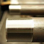
Thread gauges are precision measuring tools used to verify the dimensional accuracy and fit of threaded components. In the context of oil drilling, they are essential for inspecting the threads on casing pipes to ensure they meet industry standards and will form secure, leak-proof connections in the well.

Types of Thread Gauges:

  • Ring Gauges: Used to check the external threads of a pipe.
  • Plug Gauges: Used to inspect internal threads of a pipe or coupling.
  • Caliper-type Gauges: These gauges measure the diameter of the thread, ensuring proper size and fit.
  • API Thread Gauges: Specifically designed to meet standards set by the American Petroleum Institute (API) for oil and gas applications.

2. The Role of Casing Pipes in Oil Drilling

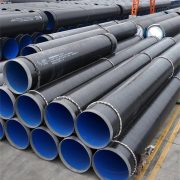
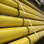
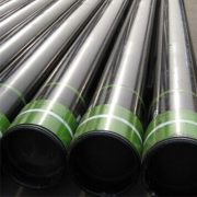
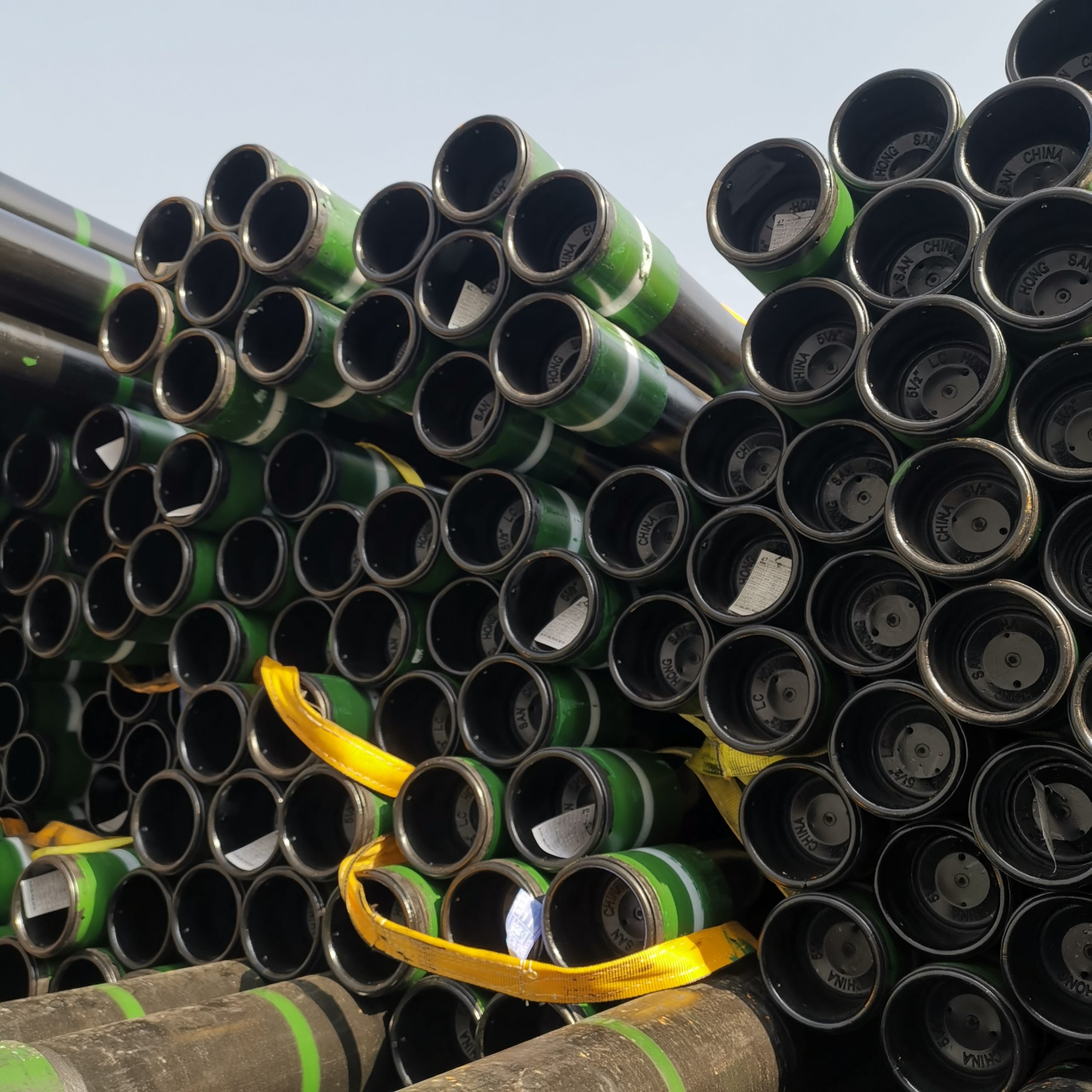
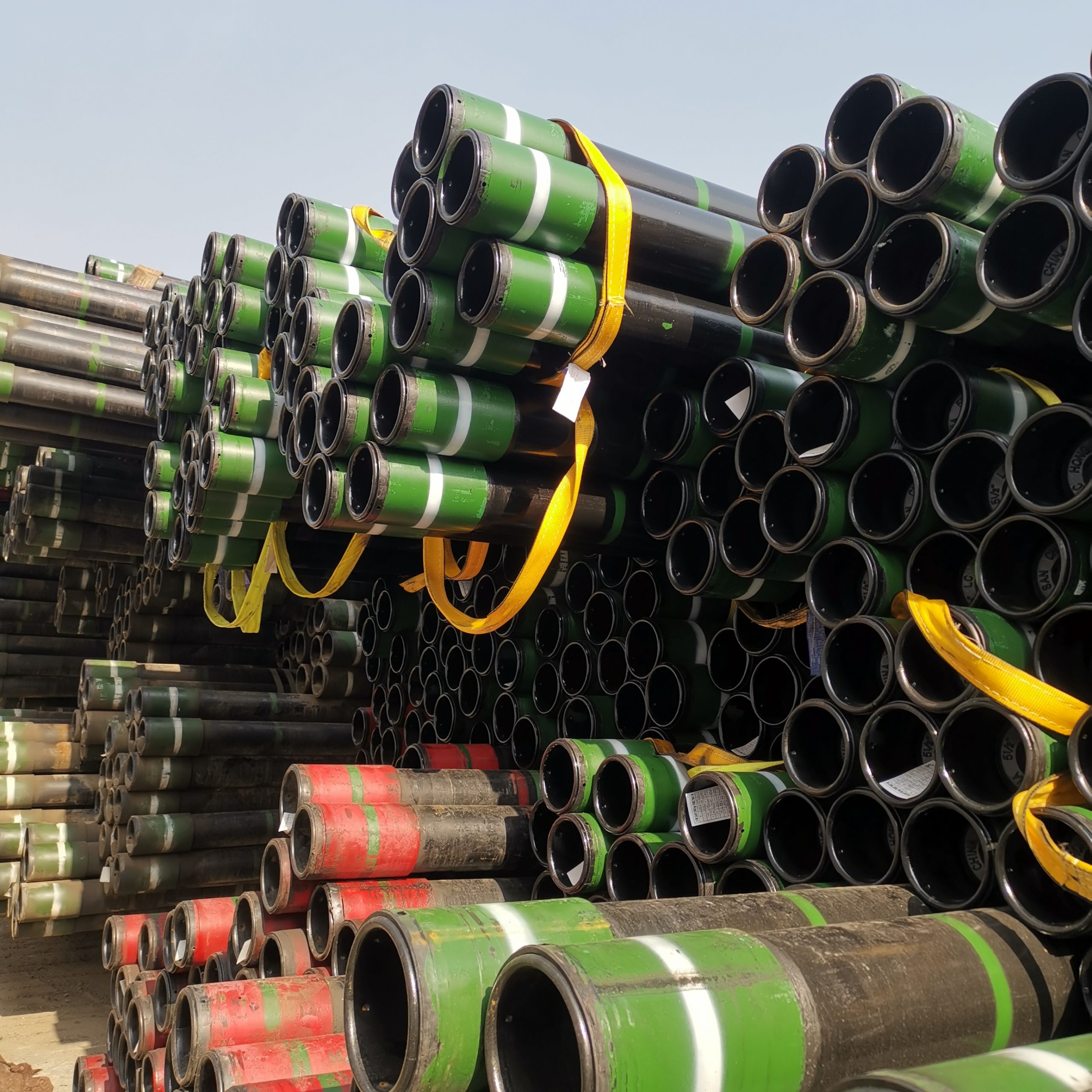
Casing pipes are used to line the wellbore during and after the drilling process. They provide structural integrity to the well and prevent contamination of groundwater, as well as ensuring that the oil or gas is safely extracted from the reservoir.

Oil wells are drilled in multiple stages, each requiring a different size of casing pipe. These pipes are connected end-to-end using threaded couplings, forming a secure and continuous casing string. Ensuring that these threaded connections are accurate and secure is critical to preventing leaks, blowouts, and other failures.

3. Why are Thread Gauges Important in Oil Drilling?

The harsh conditions encountered in oil drilling—high pressures, extreme temperatures, and corrosive environments—demand precision in every component. Thread gauges ensure that the threads on casing pipes are within tolerance, helping to:

  • Ensure a Secure Fit: Properly gauged threads ensure that pipes and couplings fit together tightly, preventing leaks that could lead to costly downtime or environmental damage.
  • Prevent Well Failure: Poorly threaded connections are one of the leading causes of well integrity issues. Thread gauges help identify manufacturing defects early, preventing catastrophic failures during drilling operations.
  • Maintain Safety: In oil drilling, safety is paramount. Thread gauges ensure that casing connections are robust enough to withstand the high pressures encountered deep underground, thereby protecting workers and equipment from potentially hazardous situations.

4. How are Thread Gauges Used in Oil Drilling Projects?

Thread gauges are used at various stages of an oil drilling project, from the manufacturing of casing pipes to field inspections. Below is a step-by-step overview of how they are applied:

1. Manufacturing Inspection:

During production, casing pipes and couplings are manufactured with precise threading to ensure a secure fit. Thread gauges are used throughout this process to verify that the threads meet the required standards. If any thread falls out of tolerance, it is either re-machined or discarded to prevent future issues.

2. Field Inspection:

Before the casing pipes are lowered into the wellbore, field engineers use thread gauges to inspect both the pipes and couplings. This ensures that the threads are still within tolerance and have not been damaged during transport or handling.

3. Recalibration and Maintenance:

Thread gauges themselves must be regularly calibrated to ensure ongoing accuracy. This is particularly important in the oil industry, where even a small discrepancy in threading can lead to costly failures.

5. Key Threading Standards in the Oil and Gas Industry

Thread gauges must comply with strict industry standards to ensure compatibility and safety in oil and gas operations. The most commonly used standards for casing pipes are defined by the American Petroleum Institute (API), which governs specifications for casing, tubing, and line pipe threads. These include:

  • API 5B: Specifies the dimensions, tolerances, and requirements for thread inspection of casing, tubing, and line pipe.
  • API 5CT: Governs the materials, manufacturing, and testing of casing and tubing for oil wells.
  • API Buttress Threads (BTC): Commonly used in casing pipes, these threads have a large load-bearing surface and are ideal for high-stress environments.

Ensuring compliance with these standards is critical, as they are designed to protect the integrity of oil and gas wells under extreme operating conditions.

6. Common Challenges in Threading for Casing Pipes and How Thread Gauges Help

1. Thread Damage During Transport:

Casing pipes are often transported to remote locations, and damage can occur during handling. Thread gauges allow for field inspection, ensuring that any damaged threads are identified and repaired before the pipes are lowered into the well.

2. Thread Wear Over Time:

In some cases, casing strings may need to be removed and reused. Over time, the threads may wear down, compromising the integrity of the connection. Thread gauges can detect wear, allowing engineers to decide if the casing pipe can be reused or if new pipes are necessary.

3. Mismatched Threads:

Different casing manufacturers may have slight variations in their threading, leading to potential issues when pipes from different sources are used in the same well. Thread gauges can help identify mismatches and ensure that all pipes used are compatible with one another.

4. Quality Assurance:

Thread gauges offer a reliable way to perform quality checks during both the manufacturing process and field operations, ensuring consistency across all casing pipes used in a project.

7. Best Practices for Using Thread Gauges in Oil Drilling

To maximize the effectiveness of thread gauges and minimize the risk of well integrity issues, operators should follow these best practices:

  • Regular Calibration of Gauges: Thread gauges should be calibrated regularly to ensure they are providing accurate measurements.
  • Training for Technicians: Ensure that field and manufacturing technicians are properly trained in the use of thread gauges and can accurately interpret the results.
  • Visual and Gauge-Based Inspections: While thread gauges provide precision, visual inspection for damage such as dents, corrosion, or wear is also critical.
  • Data Tracking: Keep records of all thread inspections to monitor patterns of wear or damage over time, allowing for predictive maintenance.

Conclusion

Thread gauges for casing pipes are a crucial component of oil drilling operations, helping ensure that casing pipes are correctly threaded and meet the stringent demands of the industry. By using thread gauges throughout the manufacturing, transport, and drilling stages, oil and gas operators can improve the safety, reliability, and efficiency of their projects.

In oil drilling, where every connection matters, the precision offered by thread gauges can mean the difference between a successful operation and a costly failure. Regular use of these tools, along with adherence to industry standards, ensures the long-term integrity of well casings and the overall safety of the drilling project.

Differences between plastic lined steel pipes and plastic coated steel pipes

Plastic-lined Steel Pipes vs Plastic-coated Steel Pipes

  1. Plastic lined steel pipe:
  • Definition: Plastic-lined steel pipe is a steel-plastic composite product made of steel pipe as the base pipe, with its inner and outer surfaces treated, zinc plating and baking paint or spray paint on the outside, and lined with polyethylene plastic or other anti-corrosion layers.
  • Classification: Plastic-lined steel pipe is divided into cold water plastic-lined steel pipe, hot water lined plastic steel pipe, and plastic rolling plastic lined steel pipe.
  • Lining plastic: polyethylene (PE), heat-resistant polyethylene (PE-RT), cross-linked polyethylene (PE-X), polypropylene (PP-R) hard polyvinyl chloride (PVC-U), chlorinated polyvinyl chloride (PVC-C).
  1. Plastic-coated steel pipe:
  • Definition: Plastic-coated steel pipe is a steel-plastic composite product that is made of steel pipe as the base pipe and plastic as the coating material. The inner and outer surfaces are melted and coated with a plastic layer or other anti-corrosive layer.
  • Classification: Plastic-coated steel pipe is divided into polyethylene-coated steel pipe and epoxy resin-coated steel pipe according to the different coating materials.
  • Plastic coating material: polyethylene powder, polyethylene tape, and epoxy resin powder.
  1. Product labeling:
  • The code number of the plastic lining steel pipe for cold water is SP-C.
  • The code number of the plastic lining steel pipe for hot water is SP-CR.
  • The polyethylene-coated steel pipe code is SP-T-PE.
  • Epoxy-coated steel pipecode is SP-T-EP.
  1. Production process:
  • Plastic lining: after the steel pipe is pre-treated, the outer wall of the plastic pipe is evenly coated with adhesive, and then placed in the steel pipe to make it expand and form a steel-plastic composite product.
  • Plastic coating: steel pipe pre-treatment after heating, high-speed plastic coating treatment, and then the formation of the steel-plastic composite products.
  1. Performance of plastic-lined steel pipes and plastic-coated steel pipes:
  • Property of plastic layer of plastic lined steel pipes:

Bonding strength: the bonding strength between the steel and the lining plastic of the plastic-lined pipe for cold water should not be less than 0.3Mpa (30N/cm2): the bonding strength between the steel and the lining plastic of the plastic-lined pipe for hot water should not be less than 1.0Mpa (100N/cm2).

External anti-corrosion performance: the product after galvanized baking paint or spray paint, at room temperature in 3% (weight, volume ratio) sodium chloride aqueous solution soaked for 24 hours, the appearance should be no corrosion white, peeling, rise, or wrinkle.

Flattening test: the plastic-lined steel pipe does not crack after 1/3 of the outer diameter of the flattened pipe, and there is no separation between the steel and the plastic.

  • Coating performance of plastic-coated steel pipe:

Pinhole test: the inner surface of the plastic-coated steel pipe was detected by an electric spark detector, and no electric spark was generated.

Adhesion: the adhesion of polyethylene coating should not be less than 30N/10mm. The adhesive force of epoxy resin coating is 1~3 grade.

Flattening test: no cracks occurred after 2/3 of the outer diameter of the polyethylene-coated steel pipe was flattened.No peeling occurred between the steel pipe and the coating after 4/5 of the outer diameter of the epoxy resin-coated steel pipe was flattened.

Usages of drill string, casing and tubing in oil drilling

Guidelines of Drill Strings, Casing and Tubing in Drilling Service

Oil drilling and production steel pipes can be generally classified into drill string (including kelly, drill pipe, weighted drill pipe, drill collar), casing (including surface casing, technical casing, oil layer casing liner), and tubing according to various structures, forms, uses and performance.

Usages of drill string, casing and tubing in oil drilling

  1. Drill string:
  • Kelly: The Kelly is located at the top of the drill string, connected with the drill pipe below. The structure is characterized by an internal round external square or an internal round external hexagon. Its function is to transfer the rotary power of the surface rotary table to the downhole bit through the drill string, to break the bottom rock layer, transfer the well-flushing fluid, cool the bit, and clean the bottom rock header.
  • Drill pipe: The drill pipe is located in the middle of the drill string, under the kelly, and weighted above the drill pipe or drill chain. The main function is to transfer the ground rotating power to the drill bit through the kelly, which serves as the intermediate medium, and gradually lengthen the connection of the drill pipe to make the depth increase continuously. Start drilling and replace the drill bit. Transfer tools and drilling fluid into the well. The drill pipe is made of two parts of pipe body and joint by friction welding. Hot-rolled alloy steel seamless pipe is adopted to increase the strength of the welded part between the pipe and the joint. The two ends of the tube body shall be upset and thickened at the welding part. The thickening forms include: internal thickening and external thickening, and internal and external thickening, respectively represented by IU, EU, and IEU symbols. Drill pipe steel grades are E-75, X-95, G-105, and S-135. Two or three digits after the letter indicate the minimum yield strength of the grade. The drill pipe joints are generally made of high-strength alloy steel by rolling, forging, heat treatment, and mechanical processing into butt welding joints of different thread types. The thread types mainly include inner flat, full hole, and normal, which are respectively represented by IF, FH, and REG. Butt weld joints of different sizes and thread types are required for drill pipes with different steel grades and specifications. Since the outside diameter of the butt welding drill pipe joint is larger than the outside diameter of the pipe body, it is easy to wear during drilling, so the joint material is required to have high strength and wear resistance. To improve the wear resistance of the joint, in addition to strengthening treatment and increasing the hardness of the joint, it is generally possible to spray welding on the surface of the joint with higher hardness and wear-resistant materials, thus greatly increasing the service life of the joint.
  • Weighted drill pipe: it is a kind of drill pipe of medium weight similar to drill pipe, with wall thickness 2-3 times of drill pipe. At both ends of the thick-walled tube body, there are extra-long extra-thick pipe joints and part of extra-thick pipe joints in the middle. The weighted drill pipe is generally added between the drill pipe and the drill collar when forming the drill string to prevent the sudden change of the drill string section and reduce the drill pipe fatigue.
  • Drill collar: located at the lower part of the drill pipe or weighted drill pipe, connected with the drill pipe or weighted drill pipe at the top and connected with the drill bit at the bottom. These include alloy drill collars, non-magnetic drill collars spiral drill collars, square drill collars, etc. By its own weight and high rigidity, apply bit pressure and bending resistance to the well, so that the bit can work smoothly, prevent well deviation, and maintain the shaft strike.
  1. Casing:

For the underground oil and gas reservoir to be transported to the surface smoothly, it is necessary to run the oil “casing” from the bottom hole to the top of the well to construct a channel to prevent blowout and leakage and isolate the different oil, gas, and water layers. Can be divided into the surface casing, technical casing, oil layer casing, and liner according to different uses.

1) Surface casing: used for drilling through the soft and prone to collapse of the ground to reinforce the shaft wall, prevent collapse, and make the drilling proceed smoothly. Common specifications are 13 3/8″ and 10 3/4.

2) Technical casing: In drilling, to prevent well collapse, leakage, and blowout in complex formation and prevent high-pressure brine layer fluid flow into the well, the technical casing must be applied to isolate and reinforce the borehole wall. Common specifications are 9 5/8″ and 8 5/8″.

3) Reservoir casing: after drilling to the target layer, to prevent interference between reservoirs with different pressures and other fluids from immersing in the well, it is necessary to go into the reservoir casing to isolate the oil, gas, and water layers, to realize layered exploitation and layered water injection. Common specifications are 4 1/2″, 5 1/2″, 6 5/8″, 7″.

Usages of drill string, casing and tubing in oil drilling

  1. Tubing:

It is mainly used for oil recovery and gas extraction, to export underground oil and gas to the surface through tubing. According to its end structure, the tubing can be divided into three types: flat tubing, external thickening tubing, and integral joint tubing.