Submarine Pipeline

Submarine Pipeline: An In-Depth Exploration

Introduction

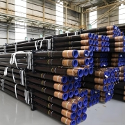
Submarine pipelines transport oil, gas, and other fluids across vast underwater distances. These pipelines are essential for connecting offshore oil and gas platforms to onshore facilities, enabling the efficient and safe transfer of resources from remote locations to the global market. However, designing, constructing, and maintaining submarine pipelines present unique challenges due to the harsh and dynamic marine environment. This blog provides a comprehensive overview of submarine pipelines, including their applications, design considerations, materials, installation methods, and maintenance strategies.

1. The Role of Submarine Pipeline in the Energy Industry

1.1 Importance of Submarine Pipelines

Submarine pipelines are the lifelines of the offshore oil and gas industry. They provide a direct and secure route for transporting hydrocarbons from offshore fields to refineries and processing plants onshore. These pipelines are essential for the global energy supply chain, particularly as the demand for oil and gas grows.

1.2 Key Applications

Oil and Gas Transportation: Submarine pipelines are primarily used to transport crude oil, natural gas, and condensates from offshore production platforms to onshore facilities for processing and distribution.
Water Injection Lines: In enhanced oil recovery (EOR) operations, submarine pipelines inject water into the reservoir to maintain pressure and improve oil recovery rates.
Subsea Umbilicals: These specialized pipelines carry control fluids, electrical power, and communication signals between subsea equipment and topside facilities.

2. Design Considerations for Submarine Pipeline

2.1 Environmental and Geotechnical Factors

Marine Environment: Submarine pipelines must be designed to withstand the corrosive effects of seawater, strong currents, and potential impacts from marine vessels or objects. The temperature and pressure conditions at the seabed also influence material selection and pipeline design.
Seabed Topography: The topography of the seabed, including slopes, valleys, and trenches, affects pipeline routing and stability. Geotechnical surveys are essential to assess the seabed conditions and determine the best pipeline route.
Seismic Activity: In regions prone to earthquakes, submarine pipelines must be designed to accommodate ground movement and prevent damage during seismic events.

2.2 Pipeline Integrity and Safety

Material Selection: Submarine pipelines are typically constructed from high-strength carbon steel, coated with anti-corrosion materials such as fusion-bonded epoxy (FBE) or three-layer polyethylene (3LPE) to protect against corrosion and mechanical damage.
Pipeline Stability: Stability is a critical concern, particularly in areas with strong currents or uneven seabed terrain. Techniques like trenching, burying, or adding concrete weight coatings stabilize the pipeline.
Leak Detection Systems: Submarine pipelines are equipped with advanced leak detection systems that monitor pressure, flow rates, and other parameters in real-time to detect leaks or anomalies.
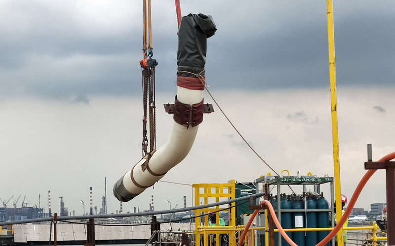
Subsea or Submarine Pipeline

Subsea or Submarine Pipeline

3. Materials Used in Submarine Pipeline Construction

3.1 Carbon Steel

Carbon steel is the most common material for submarine pipelines due to its strength, durability, and cost-effectiveness. It is typically coated with anti-corrosion layers to protect against the harsh marine environment.

3.2 Corrosion Resistant Alloys (CRAs)

In areas where pipelines are exposed to highly corrosive fluids, such as sour gas or seawater, corrosion-resistant alloys like stainless steel, duplex stainless steel, or Inconel are used. These materials offer excellent resistance to corrosion and high mechanical strength.

3.3 Coating Systems

Fusion-Bonded Epoxy (FBE): FBE coatings provide excellent corrosion protection and are commonly used for submarine pipelines.
Three-Layer Polyethylene (3LPE): 3LPE coatings consist of an epoxy primer, a polymer adhesive, and a polyethylene topcoat, offering superior mechanical protection and corrosion resistance.
Concrete Weight Coating: Concrete weight coatings are often applied to ensure stability and protect the pipeline from external damage, especially in areas with strong currents or where the pipeline is laid on the seabed.

4. Installation Methods

4.1 S-Lay Method

The S-lay method is one of the most common techniques for installing submarine pipelines. The pipeline is welded on a lay barge and gradually lowered to the seabed in an S-shaped curve. This method is suitable for shallow to medium water depths.

4.2 J-Lay Method

In the J-lay method, the pipeline is lowered vertically into the water and laid horizontally on the seabed. This technique is ideal for deepwater installations, as it reduces stress on the pipeline during the laying process.

4.3 Reel-Lay Method

The reel-lay method involves spooling the pipeline onto a large reel and then unspooling it during installation. This fast and efficient method makes it suitable for short pipelines or installations in remote locations.

4.4 Trenching and Burial

In areas with high environmental risk or where seabed stability is a concern, the pipeline is buried in a trench to provide additional protection against external forces. Trenching can be performed using plows, jetting tools, or mechanical trenchers.

5. Maintenance and Integrity Management

5.1 Inspection Techniques

In-Line Inspection (ILI): ILI tools, commonly known as “smart pigs,” are used to inspect the internal condition of submarine pipelines. These tools can detect corrosion, cracks, and other anomalies that may compromise pipeline integrity.
ROV and AUV Inspections: Remotely operated vehicles (ROVs) and autonomous underwater vehicles (AUVs) inspect the external condition of submarine pipelines. These vehicles have cameras and sensors to monitor the pipeline’s condition and identify potential issues.

5.2 Corrosion Monitoring

Cathodic Protection: Cathodic protection systems prevent corrosion on the external surface of submarine pipelines. These systems use sacrificial anodes or impressed currents to protect the pipeline from corrosive seawater.
Corrosion Inhibitors: In some cases, corrosion inhibitors are injected into the pipeline to protect the internal surfaces from corrosive fluids.

5.3 Leak Detection and Emergency Response

Real-Time Monitoring: Submarine pipelines have real-time monitoring systems that detect leaks, pressure drops, and other anomalies. Early detection is critical to preventing environmental damage and ensuring the pipeline’s safety.
Emergency Response Plans: Comprehensive emergency response plans are in place to address potential leaks or ruptures in submarine pipelines. These plans include procedures for shutting down the pipeline, containing the leak, and mitigating environmental impact.

6. Conclusion: The Future of Submarine Pipeline

As energy demand continues to grow, submarine pipelines’ importance in the global energy supply chain cannot be overstated. Advances in materials, installation techniques, and integrity management are enhancing the reliability and safety of these critical infrastructures. However, ongoing challenges such as corrosion, environmental impact, and deeper water installations require continuous innovation and improvement.
By understanding the complexities of submarine pipelines and adopting best practices in design, construction, and maintenance, the industry can ensure the safe and efficient transport of resources from offshore fields to markets worldwide.

7. FAQs

Q1: What are the main challenges in submarine pipeline construction?

The main challenges include environmental factors such as corrosion, strong currents, seabed stability, and technical challenges related to material selection, installation methods, and maintaining pipeline integrity over time.

Q2: How are submarine pipelines protected from corrosion?

Submarine pipelines are protected from corrosion through the use of anti-corrosion coatings such as FBE and 3LPE, cathodic protection systems, and corrosion-resistant materials in highly corrosive environments.

Q3: What is the importance of real-time monitoring in submarine pipelines?

Real-time monitoring is crucial for detecting leaks, pressure drops, and other anomalies that could compromise pipeline integrity. Early detection allows for quick response and mitigation, preventing environmental damage and ensuring pipeline safety.

9Cr, 13Cr, Super 13Cr, 22Cr, and 25Cr in Casing and Tubing

9Cr, 13Cr, Super 13Cr, 22Cr, and 25Cr in Casing and Tubing

Introduction

In the oil and gas industry, selecting materials for casing and tubing is crucial for ensuring the integrity, safety, and efficiency of sound operations. The choice of material is critical in environments where corrosion poses a significant threat. This blog will delve into the specifics of several corrosion-resistant alloys (CRAs) commonly used in oil casing and tubing: API 5CT L80-9Cr, API 5CT L80-9Cr, 13Cr, Super 13Cr, 22Cr, and 25Cr. We’ll explore their properties, applications, and factors when selecting the appropriate material for your well.

Understanding the Challenge: Corrosion in Oil and Gas Wells

Corrosion is a pervasive issue in the oil and gas industry, especially in wells with corrosive gases such as CO₂ and H₂S. These gases, often combined with high levels of chlorides, can lead to various forms of corrosion, including:
Uniform Corrosion: A general loss of metal thickness.
Pitting and Crevice Corrosion: Localized forms of corrosion that create deep pits or crevices, potentially leading to rapid failure.
Sulfide Stress Cracking (SSC) and Hydrogen-Induced Cracking (HIC): Caused by H₂S, these are critical forms of corrosion that can lead to catastrophic failures if not properly managed.
To combat these challenges, the industry has developed a range of CRAs, each with specific properties tailored to different environments. Below, we’ll examine some of the most commonly used CRAs.

API 5CT L80-9Cr: The Cost-Effective Solution for Moderate CO₂ Environments

API 5CT L80-9Cr is a martensitic stainless steel alloy with 9% chromium content. It is primarily used in wells where CO₂ corrosion is a concern, but H₂S levels are low to moderate.
Key Properties:
Corrosion Resistance: Provides good resistance to CO₂ corrosion but is less effective in environments with high H₂S content.
Mechanical Strength: Offers a good balance between corrosion resistance and mechanical strength, making it suitable for moderate depths and pressures.
Cost-Effective: A more economical option than higher-grade alloys, making it a popular choice for wells where corrosion conditions are not overly severe.
Applications:
Wells with moderate CO₂ levels.
Environments where H₂S content is low, or SSC is not a primary concern.

API 5CT L80-13Cr: The Industry Standard for Sweet Wells

API 5CT L80-13Cr is widely used in the oil and gas industry, particularly for “sweet” wells with high CO₂ content but low H₂S. With 13% chromium, this alloy offers enhanced corrosion resistance compared to 9Cr, making it suitable for a broader range of environments.
Key Properties:
Corrosion Resistance: Excellent resistance to CO₂ corrosion and moderate resistance to chlorides. They limited sour service capability.
Weldability: Requires careful control during welding to avoid the formation of brittle phases.
Mechanical Properties: Similar to 9Cr but with improved corrosion resistance, allowing for use in more aggressive environments.
Applications:
Sweet wells with high CO₂ and low H₂S content.
In environments with moderate chloride levels, pitting and crevice corrosion may be a concern.

Super 13Cr: Enhanced Resistance for More Aggressive Conditions

Super 13Cr is an advanced version of 13Cr stainless steel designed to offer superior corrosion resistance in more challenging environments. With improved resistance to chlorides and H₂S, it is suitable for wells that present a more aggressive corrosion profile.
Key Properties:
Enhanced Corrosion Resistance: Better performance in environments with higher chloride levels and moderate H₂S.
Toughness: Improved toughness over standard 13Cr, making it suitable for more extreme conditions.
Versatility: This can be used in sweet and mildly sour environments, offering flexibility in material selection.
Applications:
Wells with moderate to high CO₂ and H₂S levels.
Environments where the risk of pitting and crevice corrosion is elevated.

22Cr: The Duplex Solution for Sour and Chloride-Rich Environments

22Cr is duplex stainless steel containing 22% chromium, offering a balanced strength and corrosion resistance combination. Its duplex microstructure (a mix of austenitic and ferritic phases) gives it superior resistance to pitting, crevice corrosion, and SSC.
Key Properties:
High Strength: The duplex structure provides higher mechanical strength, allowing for thinner walls and lighter components.
Excellent Corrosion Resistance: Suitable for environments with high chloride content and moderate sour service (H₂S).
Cost-Effective: While more expensive than 13Cr, 22Cr offers a good balance of performance and cost, making it a popular choice for many offshore and deepwater applications.
Applications:
Sour wells with high chloride content.
Offshore and deepwater wells where mechanical strength and corrosion resistance are critical.

25Cr: The Super Duplex Stainless Steel for the Most Demanding Applications

25Cr, a super duplex stainless steel with 25% chromium, is the go-to material for the most demanding oil and gas environments. It offers unparalleled corrosion resistance, particularly in high-chloride and sour service conditions, making it ideal for deepwater and high-pressure/high-temperature (HPHT) wells.
Key Properties:
Superior Corrosion Resistance: Outstanding resistance to pitting, crevice corrosion, and stress corrosion cracking in aggressive environments.
High Mechanical Strength: The super duplex structure allows for thinner, lighter components without sacrificing strength.
Reliability: Provides a high level of reliability in extreme environments, reducing the risk of failure and associated downtime.
Applications:
Ultra-deepwater wells with high CO₂, H₂S, and chloride levels.
HPHT wells where both corrosion resistance and mechanical strength are critical.

Selecting the Right Alloy: A Practical Guide

Choosing the suitable alloy for casing and tubing depends on thoroughly understanding the healthy environment and operational conditions. Here’s a practical guide to help you make an informed decision:
Evaluate the Corrosive Environment: Assess CO₂, H₂S, and chloride levels. This will help determine the necessary corrosion resistance.
Consider Mechanical Requirements: Determine the depth, pressure, and temperature of the well to understand the material’s mechanical demands.
Balance Cost and Performance: Higher-grade alloys offer better performance but also come at a higher cost. Balance the material’s performance with the project’s budget.
Long-Term Reliability: Consider each material’s long-term reliability and maintenance costs. Higher upfront costs may be justified by reduced maintenance and longer service life.
Consult Standards and Guidelines: Adhere to industry standards such as NACE MR0175/ISO 15156 for sour service to ensure compliance and safety.

Conclusion

In the oil and gas industry, selecting casing and tubing materials is a critical decision that impacts the safety, efficiency, and profitability of oil-healthy operations. API 5CT L80-9Cr, API 5CT L80-13Cr, Super 13Cr, 22Cr, and 25Cr each offer unique properties tailored to different corrosive environments and operational conditions. By carefully assessing your well’s needs and following the guidelines outlined above, you can choose the alloy that provides the best balance of corrosion resistance, mechanical strength, and cost-effectiveness.

Ensuring the correct material selection enhances your operations’ safety and reliability and contributes to your wells’ overall success and longevity.

ASTM A553 Type I (9% Ni) Steel Plate

An Overview of ASTM A553 Type I (9% Ni) Steel Plate

Introduction

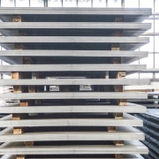
ASTM A553 Type I is a specialized steel plate incorporating 9% nickel explicitly designed for cryogenic applications. This steel is known for its remarkable toughness and strength at very low temperatures, making it an essential material in industries where extreme cold is a factor. The unique properties of ASTM A553 Type I (9% Ni) steel plate make it a critical choice for constructing storage tanks, pressure vessels, and other structures that need to withstand the challenges of cryogenic environments.

Chemical Composition

The chemical composition of ASTM A553 Type I (9% Ni) steel plate is meticulously engineered to deliver its desired properties. The 9% nickel content is the key ingredient that enhances the steel’s toughness at low temperatures. Here is the typical chemical composition:
Carbon (C): ≤ 0.13%
Manganese (Mn): ≤ 0.90% (heat analysis), ≤ 0.98% (product analysis)
Phosphorus (P): ≤ 0.015%
Sulfur (S): ≤ 0.015%
Silicon (Si): 0.15–0.40% (heat analysis), 0.13–0.45% (product analysis)
Nickel (Ni): 8.50–9.50% (heat analysis), 8.40–9.60% (product analysis)
Other Elements: Small amounts of molybdenum and niobium (columbium) may also be present in varying amounts.
The controlled carbon levels and nickel addition are significant, as they contribute to the material’s exceptional low-temperature properties.

Mechanical Properties

ASTM A553 Type I (9% Ni) steel plate is designed to offer outstanding mechanical properties, especially in environments where temperatures drop to cryogenic levels. The vital mechanical properties include:
Tensile Strength: 690–825 MPa (100–120 ksi)
Yield Strength: ≥ 585 MPa (85 ksi)
Elongation: ≥ 18% (in a 200 mm gauge length)
Impact Toughness: High toughness, tested at temperatures as low as -196°C (-321°F)
These properties are achieved through carefully controlled composition, heat treatment, and manufacturing processes. The steel’s high yield and tensile strength ensure it can handle significant stresses without deformation or failure. At the same time, its impact toughness is critical for resisting brittle fracture in cryogenic conditions.

Applications

ASTM A553 Type I (9% Ni) steel plate is specifically designed for use in environments where materials are exposed to extremely low temperatures. Some of the critical applications include:
LNG Storage Tanks: Liquefied Natural Gas (LNG) storage tanks are one of the primary applications of ASTM A553 Type I steel plates. LNG is stored at temperatures around -162°C (-260°F), requiring materials that maintain structural integrity under these conditions.
Cryogenic Vessels: Cryogenic vessels used for storing and transporting gases like nitrogen, oxygen, and hydrogen in liquid form often rely on ASTM A553 Type I steel because it can withstand low temperatures without becoming brittle.
Petrochemical Industry: This steel is frequently used in the petrochemical industry for storage tanks and piping systems for cryogenic fluids. Its resistance to brittle fracture ensures safety and reliability in these critical applications.
Aerospace: Certain components in the aerospace industry, where materials are exposed to extremely low temperatures during flight or in outer space, may use ASTM A553 Type I steel for its dependable performance.
Other Low-Temperature Applications: The properties of ASTM A553 Type I steel plates can benefit any application that requires reliable performance at low temperatures, such as certain military and research equipment.

Advantages of ASTM A553 Type I (9% Ni) Steel Plate

Superior Toughness at Low Temperatures: The addition of 9% nickel significantly improves the toughness of the steel at cryogenic temperatures, making it highly resistant to brittle fractures.
High Strength: The steel plate’s high tensile and yield strengths allow it to withstand high pressures, making it ideal for pressure vessels and other high-stress applications.
Durability and Longevity: ASTM A553 Type I steel plates are known for their durability, ensuring a long service life even in the most demanding environments.
Versatility: While it is primarily used in cryogenic applications, this steel plate’s properties make it suitable for various low-temperature applications across multiple industries.

Fabrication and Welding

ASTM A553 Type I steel plates can be fabricated and welded using standard industrial processes, although certain precautions are necessary due to the material’s high nickel content. The steel is typically delivered in a quenched and tempered condition, which enhances its mechanical properties.
Welding Considerations:
Preheat and Interpass Temperatures: Careful control of preheat and interpass temperatures is required to avoid thermal stresses that could affect the steel’s low-temperature properties.
Post-Weld Heat Treatment (PWHT): In some cases, PWHT may be required to relieve residual stresses and restore toughness.
Forming:
The steel’s high strength requires careful consideration during forming processes to avoid cracking or other issues. Cold forming is possible, but the high nickel content requires careful control of the forming process.

Standards and Specifications

ASTM A553 Type I (9% Ni) steel plate conforms to international standards, making it a globally recognized material for cryogenic applications. These standards ensure consistent quality and performance, regardless of where the steel is produced or used.
Some of the relevant standards include:
ASTM A553: Standard Specification for Pressure Vessel Plates, Alloy Steel, Quenched and Tempered 8% and 9% Nickel.
ASME Boiler and Pressure Vessel Code (BPVC) Recognizes ASTM A553 Type I steel for use in pressure vessel construction.
EN 10028-4: European standard for nickel-alloy steel plates used in pressure equipment, which includes similar materials.

Conclusion

ASTM A553 Type I (9% Ni) steel plate is a highly specialized material designed to perform under extreme conditions. Its unique combination of high strength, toughness, and resistance to brittle fracture at cryogenic temperatures makes it indispensable in industries where safety, reliability, and performance are paramount.

From LNG storage to cryogenic vessels, this steel plate’s applications are critical to the modern world. They enable the safe and efficient storage and transport of cryogenic fluids. Understanding the properties, applications, and fabrication considerations of ASTM A553 Type I steel is essential for engineers, fabricators, and industry professionals who work with cryogenic materials.

This steel’s exceptional performance is a testament to advanced metallurgical engineering, ensuring that materials can be trusted to perform without compromise, even in the harshest environments.

Finned Tubes

Guideline to Finned Tube: Enhancing Heat Transfer Efficiency

Introduction

A finned tube maximizes heat transfer efficiency between two fluids in heat exchangers. These tubes enhance thermal performance by increasing the surface area available for heat exchange. Whether utilized in power plants, HVAC systems, or chemical processing, finned tubes significantly improve heat transfer efficiency. This guide will delve into the details of finned tubes, covering their standards and grades, types of fins, materials, specifications, and suitable tube dimensions.

What Are Finned Tubes?

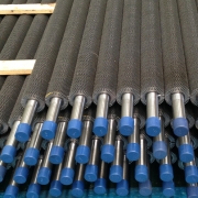
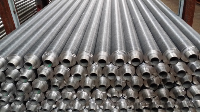
Finned tubes consist of a base tube with extended fins attached to its exterior. The fins increase the surface area, improving the heat transfer rate. These tubes are essential in applications requiring efficient thermal exchange and limited space.

Standards and Grades

Different standards and grades are used to categorize finned tubes based on their material, construction, and application:
EN 10216-2: Seamless tubes for pressure purposes:
P235GH TC1/TC2: Used in boilers and pressure vessels.
P265GH TC1/TC2: Offers higher strength for high-pressure environments.
ASTM Standards:
ASTM A179: Low-carbon steel tubes for heat exchangers and condensers.
ASTM A192: Similar to A179 but designed for higher pressures.
ASTM A213: Seamless ferritic and austenitic alloy steel tubes, including:
TP304/304L: Commonly used for its corrosion resistance and ease of welding.
TP316/316L: Preferred in environments with a higher risk of corrosion.
EN 10216-5: Stainless steel tubes:
EN 1.4301 (304): European equivalent of ASTM TP304, corrosion-resistant.
EN 1.4307 (304L): A low-carbon variant of 1.4301, ideal for welding.
EN 1.4401 (316): Offers improved resistance to chlorides.
EN 1.4404 (316L): Low-carbon version of 1.4401, suitable for welding.

Finned Tubes

Finned Tubes

Types of Fins

The fins used in finned tubes can vary based on the method of attachment and the application:
Embedded Fins: Mechanically embedded into the tube’s surface, offering a robust bond and high thermal efficiency.
Welded Fins: The fins are welded onto the tube, providing durability and mechanical strength, which is ideal for harsh environments.
Extruded Fins: Fins are extruded from the tube material, ensuring uniform heat transfer properties.

Materials for Fins

The material of the fins is selected based on the desired thermal performance and environmental conditions:
Aluminum Alloys:
AA1100: Known for its excellent thermal conductivity and corrosion resistance.
AA1080, AA1060, AA1050: These grades provide similar properties with slight differences in strength and conductivity.

Specifications: Tube Dimensions, Fin Height, Thickness, and Density

The efficiency of finned tubes depends on various factors, including the outer diameter, wall thickness, fin height, thickness, and the number of fins per inch or meter.
Tube Outer Diameter (OD): Finned tubes are typically available in outer diameters ranging from 16 mm to 219 mm (approximately 5/8″ to 8.625″). This range covers most standard applications.
Tube Wall Thickness: The wall thickness of tubes suitable for finning generally ranges from 1 mm to 8 mm. Thinner walls are more common in applications where weight and thermal conductivity are critical. In comparison, thicker walls are used for high-pressure environments.
Fin Height: Typically ranges from 6 mm to 30 mm. Higher fins increase surface area but may result in more significant pressure drops.
Fin Thickness: Ranges from 0.2 mm to 0.6 mm. Thicker fins offer better durability but may slightly reduce thermal efficiency.
The number of Fins per Inch (FPI) or per Meter (FPM) is usually between 8 to 16 FPI or 250 to 500 FPM. Higher densities provide more surface area but can also increase pressure drop.
Length of Finned Sections: The finned portion of the tube can be customized, with standard lengths ranging from 1 meter to 12 meters.

Applications and Benefits

Finned tubes are utilized in a variety of industries for their superior heat transfer capabilities:
Power Generation: Used in economizers and boilers to improve heat recovery and efficiency.
HVAC Systems: Enhance the performance of heat exchangers, contributing to better temperature control and energy savings.
Chemical Processing: In reactors and condensers, they facilitate efficient thermal management, optimizing reaction conditions and product quality.

Frequently Asked Questions (FAQs)

1. What is the purpose of finned tubes?
Finned tubes increase the surface area of heat exchangers, improving the efficiency of heat transfer between fluids.
2. What are the most common materials used for fins?
Aluminum alloys, such as AA1100, AA1080, AA1060, and AA1050, are commonly used due to their excellent thermal conductivity and corrosion resistance.
3. What are the common standards for finned tubes?
Finned tubes are manufactured according to standards like EN 10216-2 for seamless tubes and ASTM A179, A192, and A213 for various applications.
4. How do fin heights and densities affect performance?
Higher fins increase the surface area for heat transfer, while the number of fins per inch or meter affects the overall efficiency. However, higher density may also increase pressure drop.
5. What are the typical applications of finned tubes?
Finned tubes are commonly used in power generation, HVAC systems, and chemical processing to enhance heat transfer efficiency.
6. What is the typical length of a finned tube?
The finned portion of a tube typically ranges from 1 meter to 12 meters, depending on the application.

Conclusion

Finned tubes are essential in systems where effective heat transfer is crucial. Understanding the different types of fins, materials, and specifications allows engineers to select the most suitable finned tube for their application, ensuring optimal performance, longevity, and cost-efficiency.

When selecting finned tubes, it’s important to consider your system’s specific requirements, such as operating temperature, pressure, and fluids involved. Doing so can achieve the best possible thermal efficiency and system performance.

Consulting with a specialized manufacturer or supplier is highly recommended for tailored solutions and more detailed information on finned tubes. They can provide expert guidance and help you select the perfect finned tube configuration.

NACE TM0177 vs NACE TM0284

NACE TM0177 vs NACE TM0284: A Comprehensive Understanding

Introduction

Understanding the nuances of different testing methods is crucial when dealing with materials for oil and gas applications. Two prominent standards, NACE TM0177 and NACE TM0284, are frequently referenced in the industry. While both are vital for assessing materials’ resistance to hydrogen embrittlement and cracking in corrosive environments, they differ in scope, application, methodology, cost, and testing time. This guide will explore these differences, providing insights to help you make informed decisions in material selection and testing.

What Are NACE TM0177 vs NACE TM0284?

NACE TM0177

NACE TM0177, titled “Laboratory Testing of Metals for Resistance to Sulfide Stress Cracking and Stress Corrosion Cracking in H2S Environments,” is a standard that outlines four different methods (A, B, C, and D) to test metallic materials’ susceptibility to sulfide stress cracking (SSC). These methods simulate the conditions metals might face in sour environments, particularly those containing hydrogen sulfide (H2S).
Method A: Tensile Test in H2S
Method B: Bent-Beam Test in H2S
Method C: C-Ring Test in H2S
Method D: Double-Cantilever Beam (DCB) Test
Each method is designed to replicate different stress and environmental conditions, comprehensively assessing a material’s behavior in sour environments.

NACE TM0284

NACE TM0284, known as the “Evaluation of Pipeline and Pressure Vessel Steels for Resistance to Hydrogen-Induced Cracking,” focuses on testing steel’s resistance to hydrogen-induced cracking (HIC). This standard is particularly relevant for pipeline and pressure vessel steels exposed to wet H2S environments, where hydrogen can be absorbed into the steel, leading to internal cracking.
Plate Testing: The test involves exposing steel samples to a controlled sour environment and sectioning them to examine for cracks.
NACE TM0284 is typically used for evaluating carbon and low-alloy steels, providing an essential criterion for materials used in pipelines, pressure vessels, and other critical applications.

Key Differences: NACE TM0177 vs NACE TM0284

Scope of Application
NACE TM0177: Applicable to a broader range of metals and alloys, focusing on resistance to sulfide stress cracking.
NACE TM0284: Specifically designed for evaluating hydrogen-induced cracking in pipeline and pressure vessel steels.
Testing Methods
NACE TM0177: Involves multiple methods, including tensile, bent-beam, C-ring, and double-cantilever beam tests to assess SSC susceptibility.
NACE TM0284: Focuses on plate testing to evaluate HIC in steel samples.
Type of Corrosion
NACE TM0177: Primarily addresses sulfide stress cracking (SSC) and stress corrosion cracking (SCC).
NACE TM0284: Concentrates on hydrogen-induced cracking (HIC).
Material Focus
NACE TM0177: Suitable for various materials, including carbon steels, low-alloy steels, stainless steels, and nickel-based alloys.
NACE TM0284: Mainly applied to carbon and low-alloy steels used in pipelines and pressure vessels.
Cost and Testing Time
NACE TM0177:
Cost: Typically ranges from $5,000 to $15,000 per test, depending on the method used and the complexity of the test setup. Method A (Tensile Test) is generally less expensive, while Method D (Double-Cantilever Beam) tends to be more costly due to the specialized equipment required.
Testing Time: This can take anywhere from 2 weeks to 3 months, depending on the method and the specific conditions under which the test is conducted. Method B (Bent-Beam Test) and Method C (C-Ring Test) tend to be faster, while Method D might take longer.
NACE TM0284:
Cost: Generally ranges from $7,000 to $20,000 per test. The price can vary based on the sample size, the number of samples tested, and the conditions of the sour environment used during the test.
Testing Time: Typically takes 4 to 6 weeks, including sample preparation, exposure, and subsequent evaluation for cracks. The time may be extended if multiple samples are tested or the environmental conditions are more aggressive.

Practical Applications and Considerations

When to Use NACE TM0177

NACE TM0177 is best utilized when selecting materials for sour service environments, particularly in upstream oil and gas operations where H2S is prevalent. The standard is crucial for assessing the SSC resistance of materials in downhole tubing, casing, and other critical components exposed to sour gas.
Example Scenario: Selecting a material for a downhole tubing application where the presence of H2S could lead to sulfide stress cracking. NACE TM0177 testing would help ensure the chosen material can withstand these conditions.

When to Use NACE TM0284

NACE TM0284 is indispensable for evaluating pipeline and pressure vessel steels in environments where H2S is present, and HIC is a concern. This standard is often applied in midstream and downstream operations, where pipelines and pressure vessels are exposed to wet sour gas.
Example Scenario: Assessing the suitability of a carbon steel pipeline material that will transport sour gas over long distances. NACE TM0284 testing ensures the material is resistant to hydrogen-induced cracking, thereby preventing potential failures.

Choosing the Right Standard: Factors to Consider

When deciding between NACE TM0177 and NACE TM0284, consider the following factors:
Material Composition: Is the material a carbon steel, low-alloy steel, or a more specialized alloy?
Service Environment: Will the material be exposed to dry or wet H2S? What is the concentration of H2S?
Type of Corrosion Concern: Are you more concerned about sulfide stress cracking or hydrogen-induced cracking?
Component Type: Is the material intended for use in pipelines, pressure vessels, or other critical infrastructure?
Budget and Time Constraints: How much will you spend on testing, and what are your project deadlines?

Conclusion: Integrating NACE Standards into Your Material Selection Process

NACE TM0177 and NACE TM0284 are vital standards for ensuring the integrity of materials used in corrosive environments, particularly those containing hydrogen sulfide. By understanding each standard’s specific focus, cost, and time requirements, you can make informed decisions that enhance the safety and reliability of your operations.

Whether selecting materials for sour service applications or ensuring pipeline integrity, these standards provide the necessary framework to evaluate and mitigate risks associated with SSC and HIC. Integrating these standards into your material selection and testing processes will help safeguard your assets and ensure long-term operational success.

Line Pipe Steel Grades Suitable for Different Conditions in Various Global Regions

Line Pipe Steel Grades Suitable for Different Conditions in Various Global Regions

Introduction

When selecting line pipe steel grades, one must consider the unique geological, topographical, and climatic conditions of the region where these pipes will be deployed. Each area presents challenges, from temperature extremes and seismic activity to varying soil compositions and corrosion risks. This blog explains the steel grades best suited for line pipes across different regions, including North America, South America, Australia, Southeast Asia, Central Asia, the Middle East, and Africa.

1. North America

Geological and Climatic Considerations: North America’s landscape is incredibly varied, encompassing everything from the frigid Arctic regions of Canada and Alaska to the hot, arid deserts of the southwestern United States and Mexico. The region also includes significant areas of seismic activity, particularly along the West Coast, where the San Andreas Fault and other fault lines pose challenges to pipeline integrity. Additionally, the wide temperature fluctuations across seasons, from freezing winters to scorching summers, demand materials that can withstand thermal stress.
Recommended Steel Grades:
API 5L X52, X60, X65: These steel grades offer an excellent balance of strength, toughness, and weldability, making them suitable for the diverse environmental conditions in North America. Their ability to maintain structural integrity under varying temperature ranges and resist seismic stresses makes them ideal for pipelines in this region.
API 5L X70: This grade is instrumental in northern regions with prevalent frigid temperatures, as it offers superior low-temperature toughness.

2. South America

Geological and Climatic Considerations: South America consists of tropical rainforests, mountainous regions, and arid plains. The Andes Mountains, running along the continent’s western edge, pose significant challenges due to seismic activity and high-altitude conditions. The Amazon basin’s humid, corrosive environment also requires materials with excellent corrosion resistance.
Recommended Steel Grades:
API 5L X52, X60: These grades are well-suited for high-altitude, seismic-prone areas like the Andes, offering good weldability and strength. Their resilience against seismic shocks and ability to perform in various temperatures makes them ideal for this diverse region.
API 5L X65 with anti-corrosion coatings: For pipelines running through the Amazon or other humid, corrosive environments, using X65 with additional anti-corrosion measures ensures durability and longevity.

3. Australia

Geological and Climatic Considerations: Australia’s landscape is predominantly arid or semi-arid, with vast deserts in the interior and more temperate climates along the coasts. The country also has areas prone to cyclones and flooding, particularly in the northern regions. The harsh UV radiation and fluctuating temperatures in the Outback present additional challenges for pipeline materials.
Recommended Steel Grades:
API 5L X42, X52: These grades are effective in arid, desert environments due to their durability and ability to withstand temperature fluctuations. They also perform well in the presence of abrasive soils, which are common in Australia’s interior.
API 5L X65: In regions prone to cyclones and flooding, X65 provides enhanced strength and toughness, reducing the risk of damage during extreme weather events.

4. Southeast Asia

Geological and Climatic Considerations: Southeast Asia is characterized by tropical climates with high humidity, heavy rainfall, and frequent monsoons. The region is also seismically active, with several fault lines. Corrosion due to moisture and soil conditions is a significant concern.
Recommended Steel Grades:
API 5L X60, X65: These grades are optimal for Southeast Asia’s humid and corrosive environments. Their strength and toughness help them resist seismic activity and monsoon-induced flooding stresses.
API 5L X70 with advanced anti-corrosion coatings: For coastal and offshore pipelines, where saltwater corrosion is a significant issue, X70 combined with advanced coatings ensures long-term durability.

5. Central Asia

Geological and Climatic Considerations: Central Asia features vast steppe landscapes, deserts, and mountainous regions. The area experiences extreme temperature variations, from scorching summers to freezing winters. The soils in many regions are also highly corrosive, and seismic activity is a concern in certain areas.
Recommended Steel Grades:
API 5L X60, X70: These grades are ideal for Central Asia’s extreme temperature ranges and seismic conditions. Their high yield strength and toughness make them suitable for pipelines in arid and mountainous regions.
API 5L X65 with special coatings: In areas with highly corrosive soils, X65 with appropriate coatings can extend the pipeline’s lifespan and ensure safe operation.

6. The Middle East

Geological and Climatic Considerations: The Middle East is predominantly desert, with extremely high temperatures, abrasive sand, and significant UV exposure. The region also includes areas with high salt content in the soil and water, increasing the risk of corrosion. Sandstorms and high winds add to the environmental challenges.
Recommended Steel Grades:
API 5L X52, X65: These grades are well-suited for the extreme heat and abrasive conditions found in the Middle East. X65, in particular, offers superior strength, making it suitable for long-distance pipelines in this region.
API 5L X70 with advanced UV and corrosion-resistant coatings: For areas with high salt content and UV exposure, X70 combined with advanced coatings provides enhanced protection against environmental degradation.

7. Africa

Geological and Climatic Considerations: Africa’s terrain ranges from deserts like the Sahara to tropical rainforests and mountainous regions. The continent experiences extreme weather conditions, including high temperatures, heavy rainfall, and corrosive environments, particularly in coastal areas.
Recommended Steel Grades:
API 5L X52, X60: These grades provide the necessary strength and toughness to withstand Africa’s diverse and often harsh environmental conditions, including the extreme heat of the Sahara and the heavy rainfall of tropical regions.
API 5L X65 with corrosion-resistant coatings: For pipelines in coastal or rainforest areas where corrosion is a significant concern, X65 with suitable coatings ensures durability and reliable performance.

Conclusion

Selecting the correct steel grade for line pipes is crucial to ensuring the safe and efficient transportation of oil and gas across different world regions. Each region’s geological, topographical, and climatic conditions must be carefully considered when choosing the appropriate material. By matching the steel grade to the specific environmental challenges, pipeline operators can enhance their infrastructure’s safety, longevity, and performance.

FAQs

Q1: Why is choosing the correct steel grade for line pipes important?
A1: Choosing the right steel grade ensures that the pipeline can withstand the region’s specific environmental conditions, such as temperature extremes, seismic activity, and corrosive environments. This selection helps prevent failures, reduces maintenance costs, and extends the pipeline’s lifespan.

Q2: What factors should be considered when selecting steel grades for pipelines?
A2: Factors to consider include temperature variations, seismic activity, soil corrosiveness, UV exposure, and abrasive materials. Each of these factors can affect the integrity and durability of the pipeline, making it essential to choose a steel grade that can withstand these challenges.

Q3: Can the same steel grade be used in different regions?
A3: While some steel grades, like API 5L X60 and X65, are versatile and can be used in multiple regions, it’s essential to consider each area’s specific environmental conditions. In some cases, additional coatings or treatments may be required to ensure the steel grade performs well in a particular environment.

Q4: How do coatings enhance the performance of steel grades in challenging environments?
A4: Coatings provide additional protection against corrosion, UV radiation, and other environmental factors that can degrade the steel over time. Applying the appropriate coatings can significantly extend the pipeline’s lifespan, reducing the risk of leaks and failures.

Q5: What are the most common challenges pipelines face in extreme environments?
A5: Common challenges include extreme temperature fluctuations, seismic activity, corrosive soils, high UV exposure, and abrasive materials. Each can impact the pipeline’s structural integrity, making it crucial to select the appropriate steel grade and apply necessary protective measures.